Brickcom FB-100A Series User Manual
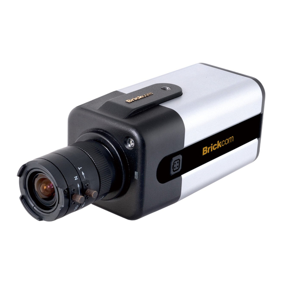
Megapixel day & night fixed box network camera
Hide thumbs
Also See for FB-100A Series:
- Quick installation manual (28 pages) ,
- User manual (139 pages) ,
- Quick installation manual (23 pages)

Related Manuals for Brickcom FB-100A Series


Summary of Contents for Brickcom FB-100A Series
- Page 1 Megapixel Day & Night Fixed Box Network Camera FB-100A Series User’s Manual Quality Service Group...
- Page 2 Product name: Network Camera (FB-100A Series) Release Date: 2010/08 Manual Revision: V2.6 Web site: www.brickcom.com Email: technical@brickcom.com info@brickcom.com ©2010 Brickcom Corporation. All Rights Reserved...
-
Page 3: Table Of Contents
Table of Contents Before You Use This Product ..................... 0 Regulatory Information....................... 0 Package Contents......................0 Fixed Box Network Camera Overview ................1 Device Appearance Description ..................3 LED Behavior........................5 Installation.......................... 8 Hardware Installation ...................... 8 System Requirements ....................10 Camera Connection...................... - Page 4 Maintenance ......................... 75 User Management ....................75 Language......................77 IP Filter ....................... 77 Firmware Upgrade ....................77 Configuration ...................... 78 Reset to Default ....................78 Reboot ........................ 78...
-
Page 5: Before You Use This Product
Before You Use This Product In many countries, there are laws prohibiting or restricting the use of surveillance devices. This Network Camera is a high-performance, web-ready camera which can be part of a flexible surveillance system. It is the user’s responsibility to ensure that the operation of this camera is legal before installing this unit for its intended use. -
Page 6: Regulatory Information
Regulatory Information Federal Communication Commission Interference Statement This equipment has been tested and found to comply with the limits for a Class B digital device, pursuant to Part 15 of the FCC Rules. These limits are designed to provide reasonable protection against harmful interference in a residential installation. -
Page 7: Package Contents
Package Contents Please check to make sure that the product package contains all the accessories listed below. a. FB-100A b. CS mount Lens (Optional) c. Product CD d. Camera Stand e. Warranty Card f. Power Adapter (Optional) g. Detachable Antenna (Optional) -
Page 8: Fixed Box Network Camera Overview
SD/SDHC memory card slot allows for local storage, which prevents data loss if the data connection is lost. Users can view live feed anywhere by internet browser or 3G mobile phone. Also, the FB-100A series can transmit the video to portable devices through other technology, such as WiMax, NAS, Digital Frame and power line. -
Page 10: Device Appearance Description
Device Appearance Description <Front Panel> Light Sensor Status LED WPS LED (*) Built-in Microphone <Rear Panel> Ethernet RJ45 10/100 Socket Power Connector (AC24V in) (Link/Power LED embedded) Power Connector (DC12V in) Detachable Antenna Auto Iris Connector (*) WPS Button (*) SD/SDHC Card Slot (*) Extension I/O Reset Button... - Page 11 <CS Mount Lens> <Optional Lens> <Vari-focal Lens with Manual Iris> --- CS Mount Iris Controller (*) Focus Controller Zoom Controller (*) <Optional Lens> <Vari-focal Lens with Auto Iris (DC Drive)> --- CS Mount Zoom Controller Focus Controller...
-
Page 12: Led Behavior
LED Behavior Function LED Behavior Description Remark WFB-100A WPS in Front Right progress (Blue) WFB-100A Connection Front Right Error (Blue) Session WFB-100A overlap Front Right detected (Blue) WFB-100A Steady on Successfully Front Right Connected (Blue) Hardware Front Left Status failure (Green) 1. - Page 13 Extension I/O Terminal Block The Network Camera provides an extension I/O terminal block which is used to connect the camera with external input/output devices. The pin definitions are listed as below. Function Power +4.5V Digital Output Digital Input Ground RS-485 - RS-485 + DI/DO Diagram...
- Page 14 Hardware Reset Reset Button The Reset Button can be used to reboot the camera or restore it to factory default settings. If the camera experiences a problem, rebooting the camera may correct the problem. If the problem remains, please restore the camera to factory default settings and reinstall the software.
-
Page 15: Installation
Installation Hardware Installation Mounting the CS-Mount Lens to the Camera <Vari-focal Lens with Manual Iris> --- Optional Lens Connect the CS-mount lens to the camera by turning it clockwise onto the camera mount until it stops. If necessary, adjust the iris controller, focus controller, and zoom controller to get the best resolution. - Page 16 <Vari-focal Lens with Auto Iris> --- Optional Lens Connect the CS-mount lens to the camera by turning it clockwise onto the camera mount until it stops. If necessary, adjust focus controller, and zoom controller to get the best resolution. Connect the lens cable plug (DC Iris control cable) to the camera side connector. To adjust the lens: The zoom controller can be manually adjusted to control the zoom factor on the camera.
-
Page 17: System Requirements
System Requirements Operating System: Microsoft Windows XP Home Edition SP2 Microsoft Windows XP Professional SP2 Computer: IBM PC/AT Compatible CPU: Pentium 3GHz or faster Memory: 1024 MB or more Monitor: 1024 x 768 pixels or more, 24-bit True color or better Network Interface: 10/100Mbps Network interface card must be installed Web Browser:... -
Page 18: Camera Connection
Camera Connection Basic Connection (Without PoE) To attach external devices, such as sensors and alarms, connect them to the extension I/O terminal block. Connect the camera to a switch using an Ethernet cable. Connect the supplied power cable to the camera and plug it into a power outle Depending on the user’s application, an Ethernet cable may be needed. - Page 19 Power over Ethernet (PoE) Connection The FB-100A is PoE compliant, so there are two options for connecting the camera to a power and Ethernet source. The camera can either be connected to a PoE-enabled switch or a non-PoE switch. A. If using a PoE-enabled switch: Use a single Ethernet cable to connect the camera to the PoE-enabled switch.
-
Page 20: Software Installation
1. Insert the Installation CD into the CD-ROM driver. Run Auto-Run Tool directly from the CD-ROM to start the installation. When installing the Brickcom software kit for the first time, select a desired language for the interface. The available languages are listed in the scroll box. - Page 21 2. In the Install Shield Wizard dialog box, click <Next> to continue. 3. Read the End-User License Agreement and check the option “I accept the terms of the license agreement”. Click <Next> to continue.
- Page 22 4. Select either “Complete” setup or “Custom” setup to install the system. a. If COMPLETE SETUP is selected: i. All program features will be installed into the default directory. Check the option “Complete” and then click <Next>. ii. Select to create shortcuts.
- Page 23 iii. The installation information will be displayed. Click <Next> to continue. b. If CUSTOM SETUP is selected: This option is recommended for advanced users. It can be used to install the system to a preferred directory or to select specific program feature(s).
- Page 24 iii. Select the features to install. Click <Next> to continue. Click <Change> to change the appointed folder where installation and program files will be stored. Click <Next> to continue.
- Page 25 v. Select programs to create shortcuts. Click <Next> to continue. vi. The installation information will be displayed. Click <Next> to continue.
- Page 26 5. To launch EasyConfig or PC-NVR Standard, select the application and click <Finish>. When launching the PC-NVR program, please refer to the PC-NVR user manual.
-
Page 27: Easyconfig
If Custom Setup type was used in the software installation and an EasyConfig icon was not installed on the desktop, the program will be installed under C:\Program Files\Brickcom\EasyConfig unless the program was saved to a preferred directory. 1. Click <Start> to continue. - Page 29 2. Select either “Simple Mode” or “Professional Mode” to obtain the camera’s IP settings. If “Simple Mode” is selected, EasyConfig will set up the connection automatically. If “Professional Mode” is selected, the user will need to configure the IP settings manually.
- Page 30 3. There may be many cameras in the local network. Differentiate the cameras using their UPnP name. Double click on the camera from the survey list to connect. 4. Enter the username and password of the camera. For first time use, the default username and password are “admin/admin.”...
- Page 31 5. For configuring the IP address settings, select either <Settings remain the same>, <Automatically obtain an IP Address (DHCP)> or <Set IP Address configuration manually>. The DHCP setting is recommended. a. If <Set IP Address configuration manually> is selected, the following pages will be displayed.
- Page 33 EasyLink is a unique Brickcom function which allows users to assign a unique domain name to their network camera’s IP address. There is no need to configure the router to open up ports or remember hard-to-memorize IP addresses.
- Page 34 7. When the IP address settings have been configured, the screen will either display a successful or failed connection message. If the connection failed, either try again or quit the installation. a. If “DHCP IP address settings” was selected, the failure page will be displayed as below: b.
- Page 35 c. If the connection was successful, the user will see the message: “Congratulations. The installation of the camera is complete.” When this window is displayed, click <PC-NVR> to start the PC-NVR program, <Live View> to view the live video from the connected IP camera, or <X> in the top right corner of the screen to close the installation window.
-
Page 36: Accessing The Network Camera
Accessing the Network Camera Check Network Settings The camera can be connected either before or immediately after the software installation. The Administrator should complete the network settings on the configuration page, including entering the correct subnet mask and IP address of gateway and DNS. Ask the network administrator or Internet service provider for the detail information. -
Page 37: Authentication
Authentication To access the camera’s live view, open a web browser and enter the IP address of the camera. A dialog window will pop requesting a username and password. As stated on the previous page, for the default username and password for the Administrator are assigned as “admin/admin”. -
Page 38: Installing The Plug-In
Installing the Plug-In For the initial access to the camera in Windows, the web browser may prompt the administrator for permission to install a new plug-in for on Internet Explorer. Permission request depends on the Internet security settings of the user’s PC or NOTEbook. If the highest security level is set, the computer may prohibit any installation and execution attempt. -
Page 39: Live View
Live View Note - (*) These are optional features. Please refer to the Product List for the full list of optional features available for the product. Live View is the default page that opens when accessing the camera. Live video is displayed directly in the browser window. - Page 40 Recording on/off - Displays the status of recording video MIC on /off - Displays the status of the MIC volume Speaker on/off - Displays the status of the Speaker MD on/off - Displays the status of Motion Detection Brightness - Drag the slider bar to adjust the image brightness level. Mic volume - Drag the slider bar to adjust the microphone volume.
- Page 41 Talk – To communicate through the camera using the computer MIC. Set Default – Reset to default settings. NOTE The <Camera Control Panel> functions have no effect on the recorded video. Whatever changes are made to the <Camera Control Panel> will not be applied to the recorded video.
-
Page 42: Configuration
Configuration Click <Configuration> on the main page to change the camera settings pages. Note: Only Administrators can access the Configuration page. Camera/Video/Audio Camera Brightness - Drag the slider bar to adjust the image brightness level from -5 to +5. Contrast - Drag the slider bar to adjust the image contrast level from -5 to +5. Sharpness - Drag the slider bar to adjust the image sharpness level from -5 to +5. - Page 43 Exposure Control Sport – Select this option when monitoring rapid moving objects. Normal – Select this option for normal monitoring conditions. Night Vision – Select this option when monitoring at night or in low light conditions. User Defined – Select this option to define the exposure manually. AGC (Auto Gain Control) - The AGC can be set between 1X to 5X.
- Page 44 True Day & Night Auto - The Network Camera automatically removes the filter by judging the level of ambient light. Manual - In day mode, enable the IR CUT to keep the IR cut filter active at all times so the infrared light does not reach the sensor and distort the color. In night mode, disable the IR CUT to deactivate the IR cut filter at all times so the sensor accepts infrared light and improves low light sensitivity.
-
Page 45: Video
Video The Network Camera offers two separate streams for different viewing options. Stream 1 & Stream 2 Video Codec - The Network Camera offers three choices of video codec standards for real-time viewing: H.264, MPEG-4 and MJPEG. Video Resolution - Select from the drop-down menu to choose the best resolution recording settings. - Page 46 NOTE - a higher bitrate will use higher network bandwidth. The video quality can be set between Level 1 to Level 6, with Level 6 producing the best image quality. HTTP Transport – If MJPEG is used for Video Codec, users can enable HTTP Transport protocol for video communication.
- Page 47 Video Overlay Timestamp To display the date and time on the screen during live view, check “Enable” to enable the timestamp function and select the display position from the drop-down menu. Text To make a NOTE about the camera, check “Enable” and select the display position from the drop-down menu.
- Page 48 RTSP Server To utilize RTSP authentication, the user must first set a password for the camera. RTSP (Real-Time Streaming Protocol) controls the delivery of streaming media. By default the port number is set to 554. Authentication - Depending on the network security requirements, the camera provides two types of security settings for streaming via RTSP protocol: NONE and DIGEST.
-
Page 49: Audio
Audio The administrator can set up two separate streams for the camera for different viewing devices. The administrator can enable or disable the audio function on either stream. If audio enable is selected, select the Audio codec from the drop-down menu. Advanced Settings Camera MIC –... -
Page 50: Multicast
Multicast Multicast sends a video stream to the multicast group address and allows multiple clients to acquire the stream at the same time by requesting a copy from the multicast group address. Therefore, multicast can effectively save Internet bandwidth. The RTSP (Real-Time Streaming Protocol) controls the delivery of streaming media. -
Page 51: Network
Network IP Settings This section explains how to configure a wired network connection for the camera. There are several ways to setup the camera over the Internet: (1) obtain an available dynamic IP address assigned by a DHCP server, (2) use a static IP, or use PPPoE (Point-to-point over Ethernet). -
Page 52: Upnp
3. PPPoE (Point-to-point over Ethernet): Use this mode if connecting to the Internet through a DSL Line. NOTE - To utilize this feature, it requires an account provided by an Internet Service Provider. Enter the user name and password provided by the ISP. Click Apply to apply settings or Cancel to cancel changes. -
Page 53: Ddns (Dynamic Domain Name Service)
DDNS (dynamic domain name service) DDNS links a domain name to an IP address, allowing users to easily access their camera even with a changing IP address. Brickcom network cameras are compatible with two DDNS service providers (1) DynDNS, and (2) TZO. -
Page 54: Easylink Tm
EasyLink EasyLink is a unique Brickcom function which allows users to assign a unique domain name to their network camera’s IP address. There is no need to configure the router to open up ports or remember hard-to-memorize IP addresses. When this function is enabled, users can log onto [uniquedomainname].mybrickcom.com to view the camera’s... -
Page 55: Wireless
Wireless devices have a default SSID set by the factory. Brickcom wireless products use Brickcom as the default name. It is recommended for users to rename their SSID to something unique in order to distinguish their wireless device from surrounding wireless networks. - Page 56 Security - Encryption protects data transmitted over a wireless network. Wi-Fi Protected Access (WPA-Personal/WPA2-personal) and Wired Equivalent Privacy (WEP) offer different levels of security for wireless communication. A network encrypted with WPA-Personal/WPA2-personal is more secure than a network encrypted with WEP because WPA-Personal/WPA2-personal uses dynamic key encryption.
- Page 57 WEP- Wired Equivalent Privacy (WEP) is a basic encryption method which transmits network broadcast messages using radio signals. It is not as secure as WPA. Tx Key - Select a key from the drop-down menu. WEP Encryption - Select a level of WEP encryption: 64 bits 10 hex digits or 128 bits 26 hex digits.
- Page 58 WPA-Personal - WiFi Protected Access (WPA)-Personal Encryption - Supports two encryption methods with dynamic encryption keys: Temporal Key Integrity Protocol (TKIP) and Advanced Encryption Standard (AES). Select the algorithm type from the drop down menu: TKIP or AES. The default is TKIP. Shared Key - Enter the key shared between the Router and the server keys.
- Page 59 WPA2-Personal- WiFi Protected Access (WPA2-Personal) Encryption - WPA2 supports AES encryption method with dynamic encryption keys. Shared Key - Enter the key shared between the Router and the server keys. Enter a password of 8-63 characters. NOTE - If using WPA or WPA2, each device in the wireless network must use the same WPA or WPA2 method and shared key or else the network will not function properly.
- Page 60 Advanced Settings Network Mode - From the drop-down menu, select the wireless standards running on the network. • If there are Wireless-B, Wireless-G and Wireless-N (2.4GHz) devices on the network, use the default setting, BGN-Mixed. • If there are Wireless-B and Wireless-G devices on the network, select BG-Mixed. •...
- Page 61 Wi-Fi Protected Setup Use this method if the client device has a Wi-Fi Protected Setup PIN number. 1. Enter the network name from the device in the field. 2. Click <Register> to start WPS. 3. Click “Enable” to enable the WPS Button. If this feature is not enabled, the user will not be able to use the WPS button Click Apply to apply settings or Cancel to cancel changes.
-
Page 62: Http/Https
HTTP/HTTPS HTTP – (HyperText Transfer Protocol) - This protocol allows for TCP protocol quality without having to open specific ports for streaming. Users inside a firewall can utilize this protocol to allow streaming data through. HTTPS - (Hypertext Transfer Protocol over SSL) - This protocol allows authentication and encrypted communication over SSL (Secure Socket Layer). - Page 63 2. Enter the User name and Password of the camera. 3. Click “Certificate Error” on the top right corner of the window to view the certificate. 4. Click “Install Certificate” and follow the steps to finish the installation.
-
Page 64: Event
Event Event Settings When an event (such as unauthorized movement) occurs, the camera can be scheduled to perform certain actions. An Event Type is a set of parameters that defines these actions. This section describes how to configure the camera to perform certain actions when events occur. - Page 65 How to Set Up an Event Schedule Event Schedule describes how and when the camera performs certain actions. Check “Enable” and enter a descriptive name for the event schedule. Set Event Schedule to define when the event is activated by selecting from Always (24 hours), Schedule or Recurrence pattern.
- Page 66 b. If Recurrence Pattern is selected, the following page will be displayed. i. An event schedule can be programmed to recur at different times according to the user’s needs. Select the days for the event schedule to occur. Select a start time and specify the duration. 3.
- Page 67 a. When <Send to Email> is selected, the following page will be shown: i. From - Enter the email address of the sender. ii. To - Enter the email address of the recipient. To enter multiple recipients, separate each using a comma. iii.
-
Page 68: Motion Detection
Motion Detection Motion can be detected by measuring changes in the speed or vector of an object or objects in the monitored area. This section explains how to configure the Network Camera to enable motion detection. Detection Setting – Use this setting to enable and define the motion detection windows. The user can defined up to three areas on the live view window for motion detection. - Page 69 The chart below the Live View window indicates the activity level of the Motion Detection window. When motion is detected by the camera and exceeds the defined threshold, a red bar will appear. Users can use this feature as a trigger source to send photos or videos to a remote server via email or FTP.
-
Page 70: Digital Input (Di)
Digital Input (DI) The DI socket allows the IP camera to receive input from an external device. The external device should have the ability to drive voltage on the connected DI wire to the triggering voltage level in order to notify the IP camera of any event of interest. The IP camera will then process the event notification according to the specific event rules. -
Page 71: Notifications
Notifications Use the tools in this section to specify what type of notification will be sent when an event occurs. The camera can send buffered images to an FTP server, Samba, Email, or HTTP. FTP Settings File Transfer Protocol (FTP) is used as an application component to automatically transfer files for program internal functions. -
Page 72: E-Mail Settings
E-mail Settings Select “Primary Email Server” option from the Server Selection drop down menu to send media files to an email server when an event is triggered. SMTP Server - Enter the server host name of the email server. SMTP Port - Enter the port number of the email server; by default, the SMTP port is set to 25. -
Page 73: Samba Settings
Samba Settings Select this option to send the media files via a network neighborhood when an event is triggered. Server Address - Enter the IP address of the Samba server. User Name - Enter the user name of the Samba server. Password - Enter the password of the Samba server. -
Page 74: Http Settings
HTTP Settings Select this option to send the media files via an HTTP notification when an event is triggered. URL –Specify the URL to send HTTP requests. The URL is normally written as: http://ip_address/ notification.cgi?parameter ip_address – type the IP address or host name of the HTTP host. Parameter –... -
Page 75: Digital Output (Do)
Digital Output (DO) The DO socket allows the IP camera to send output to an external device. While executing the DO notification action, the IP camera drives voltage on the connected DO wire to the triggering voltage level for X number of seconds. The connected external device will then be triggered for X number of seconds. -
Page 76: System
System System Log Log – Set up the camera to record a system log when an event is triggered. This page displays the system’s log in chronological order. The system log is stored in the camera’s buffer area and will be overwritten when the buffer area is full. Click Retrieve to retrieve the log or click Save to file to save the system log. - Page 77 Remote Logging The user can configure the camera to send the system log file to a remote server as a log backup. Click to enable remote log and enter the IP address of the remote server. Enter the port number of the remote server. Click Apply to apply settings or Cancel to cancel changes.
-
Page 78: Date And Time
Date and Time Manual – Manually enter the date and time. Clone from PC – The camera will sync with the time, date and time zone of the computer used to modify the camera settings. Check “Clone” to utilize this option. The read-only date and time of the PC will be displayed. -
Page 79: Device Information
Device Information System Information –Displays the complete system information of the camera. Network Settings –Displays the complete network settings information of the camera. Video/Audio Settings –Displays the complete video/audio settings information of the camera. -
Page 80: Storage Management (*)
Storage Management (*) Storage Management is used to view all the recorded files on the SD/SDHC card. Click Reload to refresh the list of recorded files. Click Remove to safely remove the SD/SDHC memory card. Left click on the folder to list the recorded files. The user can either play the snapshot of the recorded files by moving the mouse pointer over the file or double click on a file to play Right click on the folder to download, play or delete the recorded files. - Page 81 Advanced Settings (*) Automatic Recycle(*) – Enable to automatically overwrite older files when the available space remaining on the Micro-SD/SDHC card is less than 100MB. If the Automatic Recycle function is disabled, there must be at least 50MB hard drive space available for the camera to be able to record video files.
-
Page 82: Maintenance
Maintenance User Management This section explains how to enable password protection and create multiple accounts. The administrator account name is “admin”, which is permanent and cannot be deleted. Click Add to create an account. Enter the new user’s name, password and confirm password. Administrators can add up to 10 user accounts. - Page 83 ♦ Administrator - user has access to view and change the Configuration page. Users with administrator privilege can change other user’s access rights and delete user accounts. Click Delete or Update to delete or modify a user’s account. ♦ Viewer - user can only access the main page for live viewing. ♦...
-
Page 84: Language
Language Select the desired language from the drop-down menu. Click Apply to apply settings or Cancel to cancel changes. IP Filter The IP Filter is used to filter the IP addresses which are able to access the network camera. Enable the IP Filter and select to allow or deny a range of IP addresses access to the server. -
Page 85: Configuration
Configuration This feature allows the user to export/import the configuration files of the network camera. Import/Export - Click export to pop up a dialog to indicate the location and file to export. Click browse to indicate the location and file of the camera configuration and click import to import the configuration file back into the network camera.
Need help?
Do you have a question about the FB-100A Series and is the answer not in the manual?
Questions and answers