
Subscribe to Our Youtube Channel
Related Manuals for Brickcom Merge FD-300Ap


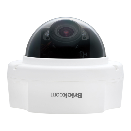
Summary of Contents for Brickcom Merge FD-300Ap
- Page 1 Hardware User’s Manual Megapixel Day & Night Fixed Dome Network Camera Quality Service Group Fixed Dome Series...
- Page 2 Review History: 1. Separate User Manual into HW and SW. Merge FD-300Ap/ FD-130N/ FD-132N/ FD-300A/ FD-302A/ FD-500A/ FD-502A series into this User Manual. 3. Merge FD-200Np V6/ FD-202Ne V6/ FD-300Np Star/ FD-302Ne Star/ FD-500Ap V6/ FD-502Ae V6 Product name: Network Camera (Fixed Dome series)
-
Page 3: Table Of Contents
Table of Contents Before You Use This Product ..................1 Regulatory Information ....................2 Chapter 1 - Package Contents ..................3 Chapter 2 - Fixed Dome Network Camera Overview........... 4 Chapter 3 - Device Appearance Description ............... 5 Chapter 4 - LED Behavior ..................... 8 Chapter 5 - Installation .................... -
Page 4: Before You Use This Product
Before You Use This Product In many countries, there are laws prohibiting or restricting the use of surveillance devices. This Network Camera is a high-performance, web-ready camera which can be part of a flexible surveillance system. It is the user’s responsibility to ensure that the operation of this camera is legal before installing this unit for its intended use. -
Page 5: Regulatory Information
Regulatory Information Federal Communication Commission Interference Statement This equipment has been tested and found to comply with the limits for a Class B digital device, pursuant to Part 15 of the FCC Rules. These limits are designed to provide reasonable protection against harmful interference in a residential installation. This equipment generates uses and can radiate radio frequency energy and, if not installed and used in accordance with the instructions, may cause harmful interference to radio communications. -
Page 6: Chapter 1 - Package Contents
Chapter 1 - Package Contents a. Network Camera b. Terminal Block (Fixed Dome series) c. Product CD d. Location Sticker e. Warranty Card f. Screw Bag g. Easy Installation Guide h. L-WM-01(Optional) -
Page 7: Chapter 2 - Fixed Dome Network Camera Overview
Chapter 2 - Fixed Dome Network Camera Overview The FIXED DOME SERIES is a full-featured, 3-axis, fixed-dome, network camera. With a megapixel progressive sensor and built-in IR-cut filter/ IR illuminator LEDs/ Auto Light sensor, it can provide 24-hour, indoor surveillance. The FIXED DOME SERIES features a wide-angle and vari-focal lens, which offers wide view coverage of all angles. -
Page 8: Chapter 3 - Device Appearance Description
Chapter 3 - Device Appearance Description Below “ Device Appearance Description” is for FD-200Np V6/ FD-202Ne V6/ FD-300Np Star/ FD-302Ne Star/ FD-502Ap V6/ FD-502Ae V6 2. Below “ Device Appearance Description” is for FD-200Np/ FD-202Np/ FD-300Np/ FD-302Np/ FD-200Ap/ FD-202Ap/ FD-302Ap/ FD-500Ap/ FD-502A... - Page 9 3. Below “ Device Appearance Description” is for FD-300Ap LENS Video Adjustment Screw SD Card Slot RJ45 Connector Tilt Screw Conduit Plug and Conduit Hole Reset Button Terminal Block Terminal Block (For Power) (For Audio in/out, DI/DO) 4. Below “ Device Appearance Description” is for FD-501Af-series LENS IR Leds RJ45 Connector...
- Page 10 Focus Control Bar (*) View Angle Control Bar (*) SD/SDHC Card Slot (*) Focus Control Bar (*) View Angle Control Bar (*) SD/SDHC Card Slot (*) NOTE 1. SD Card Capacity (*) - The network camera is compatible with SD/SDHC/SDXC (Maximum 64GB) cards.
-
Page 11: Chapter 4 - Led Behavior
Chapter 4 - LED Behavior Function LED Behavior Description Power LED Continuous illumination (Green) Power on Power LED Unit Power off Link LED Continuous illumination (Red) Link Link LED Blinking (Red) Connecting < Extension I/O Terminal Block > The Network Camera provides an extension I/O terminal block which is used to connect the camera with external input/output devices. - Page 12 < Hardware Reset > The Reset Button can be used to reboot the camera, restore it to factory default settings, or switch on FocusEasy. If the camera experiences a problem, rebooting the camera may correct the problem. If the problem remains, please restore the camera to factory default settings and reinstall the software.
-
Page 13: Chapter 5 - Installation
Chapter 5 - Installation 5.1 Hardware Installation A. Remove the dome cover from the camera device PoE, Power, DIDO, Audio Connection Insert the PoE(1) / DC12V(2), DIDO and Audio cable(3) through conduit hole A or B. - Page 14 a. PoE, Power, DIDO, Audio Connection ii. Connect the PoE (1)/ DC 12V (2), DIDO and Audio (3) Cables to their respective terminals. See the next page for more details regarding the DIDO and Audio connection. 1) Power over Ethernet (PoE) Connection 2) Power Adapter Connection Please refer to the definition of the terminal blocks below.
- Page 15 3) DIDO and Audio Connection Please refer to the definition of the terminal blocks below. It is also printed on the motherboard. Terminal Block Pin No. Function Pin 1 Pin 2 Pin 3 Pin 4 DIDO GND Pin 5 Audio OUT Pin 6 DGND Pin 7...
- Page 16 3) Hammer the four plastic anchors which are provided in the product package into the two location holes. 4) Mount the camera on the wall and position to two screw slots over the plastic anchors. Insert the screams into the holes and use the screwdriver to tighten the screws clockwise until they are secure.
- Page 17 C. For ceiling installation: The user needs the two screws which are included in the product package and a screwdriver. Mount the camera on the desired location and use the screwdriver to tighten the screws clockwise through the two holes on each side of the device as shown below.
- Page 18 ii. Release the tilt screw on both side of the device and then rotate the lens to up or down. After completion, tighten the tilt screw. iii. Release the video adjustment screw and then adjust the lens direction. After completion, tighten the video adjustment screw.
- Page 19 b. How to adjust the view angle and focus range i. Release the view angle controller and then moving the controller bar left or right to adjust the view angle. After completion, tighten the view angle controller. ii. Release the focus controller and then moving the controller bar left or right to adjust the focus range.
-
Page 20: Camera Connection
5.2 Camera Connection F. Basic Connection (Without PoE) a. Connect the power adaptor to the camera device. b. Connect the camera to the Ethernet hub using a RJ45 Ethernet cable. G. Power over Ethernet (PoE) Connection a. Connect the camera to a PoE-enabled hub via single Ethernet cable. b. -
Page 21: System Requirements
5.3 System Requirements Operating System: Microsoft Windows 8.1/8/7/Vista/XP/2000/ Computer: IBM PC/AT Compatible CPU: Pentium 3GHz or faster Memory: 1024 MB or more Monitor: 1024 x 768 pixels or more, 24-bit True color or better Network Interface: 10/100Mbps Network interface card must be installed Web Browser: Microsoft Internet Explorer 6.0 SP2 or higher Adobe Reader:... -
Page 22: Software Installation
A. Insert the Installation CD into the CD-ROM driver. Run Auto-Run Tool directly from the CD-ROM to start the installation. When installing the Brickcom software kit for the first time, select a desired language for the interface. The available languages are listed in the scroll box. Click <Install>... - Page 23 B. In the Install Shield Wizard dialog box, click <Next> to continue. C. Read the End-User License Agreement and check the option “I accept the terms of the license agreement”. Click <Next> to continue.
- Page 24 D. Click <Change> to change the appointed folder where installation and program files will be stored. Click <Next> to continue. E. Select to create shortcuts. Click <Next> to continue.
- Page 25 F. Select the application and click <Finish>. When launching the PC-NVR program, please refer to the PC-NVR user manual.
-
Page 26: Easyconfig
If Custom Setup type was used in the software installation and an EasyConfig icon was not installed on the desktop, the program will be installed under C:\Program Files\Brickcom\EasyConfig unless the program was saved to a preferred directory. A. Click <Start> to continue. The program will automatically search for the camera in the intranet. - Page 28 B. Select either “Simple Mode” or “Professional Mode” to obtain the camera’s IP settings. If “Simple Mode” is selected, EasyConfig will set up the connection automatically. If “Professional Mode” is selected, the user will need to configure the IP settings manually.
- Page 29 C. There may be many cameras in the local network. Differentiate the cameras using their UPnP name. Double click on the camera from the survey list to connect. D. For configuring the IP address settings, select either <Settings remain the same>, <Automatically obtain an IP Address (DHCP)>...
- Page 30 If <Set IP Address configuration manually> is selected, the following pages will be displayed.
- Page 31 Otherwise, this page will not be shown. *If desired, click <Skip> to skip this setting. EasyLinkTM is a unique Brickcom function which allows users to assign a unique EasyLink name to their network camera’s IP address. There is no...
- Page 32 F. When the IP address settings have been configured, the screen will either display a successful or failed connection message. If the connection failed, either try again or quit the installation. a. If “DHCP IP address settings” was selected, the failure page will be displayed as below: b.
- Page 33 After connecting to the network Vandal Dome Camera, the request for installing the ActiveX control will appear below the URL bar. Right click on the bar, and click “Install Brickcom ActiveX Control.” to permit ActiveX control installation. In the pop-up security warning window, click “Install” to start downloading Viewer software on the PC.
Need help?
Do you have a question about the Merge FD-300Ap and is the answer not in the manual?
Questions and answers