Table of Contents
Advertisement
Quick Links
Download this manual
See also:
User Manual
Advertisement
Table of Contents

Related Manuals for Brickcom FB-100Ap Series


Summary of Contents for Brickcom FB-100Ap Series
- Page 1 Hardware User’s Manual Megapixel Day & Night Fixed Box Network Camera Quality Service Group Fixed Box Series...
- Page 2 4. Merge (W)FB-300Np V5 feature version 5. Merge FB-500/300/200 & FB-H 6. Merge WDRPro Series Product name: Network Camera (Fixed Box series) Release Date: 2015/09 Manual Revision: V6.0 Web site: www.brickcom.com support@brickcom.com Email: info@brickcom.com © 2015 Brickcom Corporation. All Rights Reserved...
-
Page 3: Table Of Contents
Table of Contents Before You Use This Product ..............3 Regulatory Information ................4 Chapter 1- Package Contents ..............5 Chapter 2- Fixed Box Network Camera Overview ........... 6 Chapter 3- Device Appearance Description ........... 7 Chapter 4 - LED Indicators ............... 12 Chapter 5- Installation ................ -
Page 4: Before You Use This Product
Before You Use This Product In many countries, there are laws prohibiting or restricting the use of surveillance devices. This Network Camera is a high-performance, web-ready camera which can be part of a flexible surveillance system. It is user’s responsibility to ensure that the operation of this camera is legal before installing this unit for its intended use. -
Page 5: Regulatory Information
Regulatory Information Federal Communication Commission Interference Statement This equipment has been tested and found to comply with the limits for a Class B digital device, pursuant to Part 15 of the FCC Rules. These limits are designed to provide reasonable protection against harmful interference in a residential installation. This equipment generates uses and can radiate radio frequency energy and, if not installed and used in accordance with the instructions, may cause harmful interference to radio communications. -
Page 6: Chapter 1- Package Contents
Chapter 1- Package Contents Please check to make sure that the product package contains all the accessories listed below. b. CS mount Lens (Optional) Network Camera c. Product CD d. Camera Stand e. Warranty Card Allen Key g. Power Adapter (Optional) h. -
Page 7: Chapter 2- Fixed Box Network Camera Overview
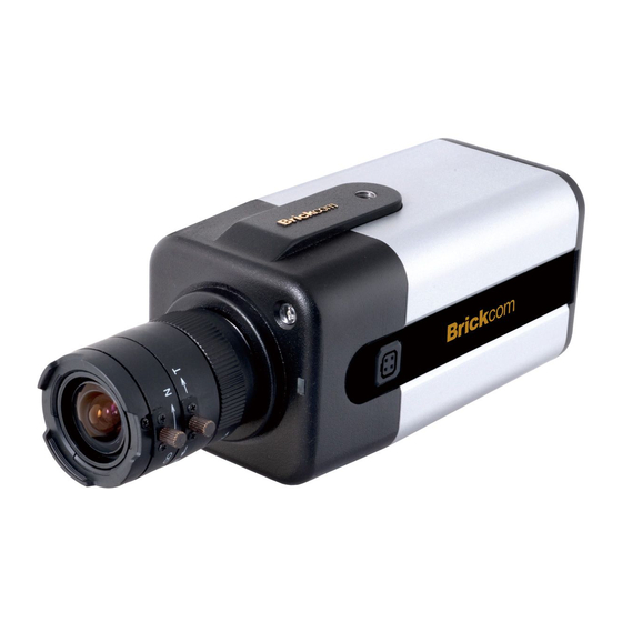
Chapter 2- Fixed Box Network Camera Overview The Brickcom Fixed Box series offers a reliable and efficient solution for 24-hour video surveillance. The Fixed Box series offers highly efficient H.264 video compression, which reduces bandwidth and storage requirements without compromising image quality. -
Page 8: Chapter 3- Device Appearance Description
Chapter 3- Device Appearance Description Photo Indication & Dimension Diagram FB Series Power Connector Status LED (DC12V In) Power Connector (AC24V In) Detachable Antenna (WIFI series) Light Sensor Ethernet RJ45 10/100 Socket (Link/Power LED embedded) WPS Button (WIFI Series) WPS LED (WIFI SD/SDHC Card Slot series) Extension I/O Terminal... - Page 9 Photo Indication & Dimension Diagram - (W)FB-300Np V5 Series Only FB-H Series Power Connector (DC12V In) Light Sensor Power Connector (AC24V In) Ethernet RJ45 10/100 Socket (Link/Power LED embedded) WPS LED Antenna Connector (WIFI series) WPS Button (WIFI series) USB Port Status LED TV Out Micro SD/SDHC/SDXC Card Slot...
- Page 10 CS Mount Lens -Optional <Vari-focal Lens with Manual Iris> --- CS Mount Iris Controller (*) Focus Controller Zoom Controller (*) <Optional Lens> <Vari-focal Lens with Auto Iris> (DC Drive) --- CS Mount Zoom Controller Focus Controller Extension I/O Terminal Block The Network Camera provides an extension I/O terminal block which is used to connect the camera with external input/output devices.
- Page 11 / +12V* / +12V* / +12V* *V5&V6 (WDRPro & Star & StarPlus) Series Supported Hardware Reset The Reset Button can be used to reboot the camera, restore it to factory default settings, or switch on FocusEasy. If the camera experiences a problem, rebooting the camera may correct the problem.
- Page 12 cameras, and is NOT supported on any moto-focal cameras. To Reset Press and hold the Reset Button for more than 10 seconds using a paper clip or thin object. Wait for the camera to reset to default. NOTE - By resetting the camera, all settings will be restored to the factory default settings.
-
Page 13: Chapter 4 - Led Indicators
Chapter 4 - LED Indicators Function Front LED Behavior Description Remark WPS in process Right Blue) Steady Successfully Connected Lens FocusEasy™ Right Steady focusing (red) (V5 Series only) in process Hardware failure Normal Steady Operation Left Status (Green) Unlit Power Off While F/W upgrading Function... -
Page 14: Chapter 5- Installation
Chapter 5- Installation 5.1 Hardware Installation Mounting the CS-Mount Lens to the Camera <Vari-focal Lens with Manual Iris> --- Optional Lens Connect the CS-mount lens to the IP camera by turning it clockwise. If necessary, adjust the iris controller, focus controller, and zoom controller to get the best image condition. - Page 15 image gets closer to the focus, the beeps go faster, just like the car reverse radar. Once the image is focused, the buzzer will make a long beep for 3 seconds for notification. <Vari-focal Lens with Auto Iris> --- Optional Lens Connect the CS-mount lens to the camera by turning it clockwise onto the camera mount until it stops.
-
Page 16: Camera Connection
5.2 Camera Connection Note: If there is no DHCP server on the network, the camera will operate with the IP address 192.168.1.245. Please make sure your computer's network interface is configured to the same subnet as the camera. Connection to Non-PoE (Power over Ethernet) Switch or Router 1) Power the camera by plugging the power adaptor to the outlet and the DC jack to the camera. - Page 17 Connection to PoE Switch or Router or Injector A. PoE Switch or Router: 1) Connect the camera to the PoE switch or router with the RJ-45 Ethernet cable. B. PoE injector: 1) Connect the camera to the OUT port ("DATA+Power" port, etc.) of the PoE injector with the RJ-45 Ethernet cable.
-
Page 18: System Requirements
5.3 System Requirements Operating System: Microsoft Windows 8.1/8/7/Vista/XP/2000 Computer: IBM PC/AT Compatible CPU: Pentium 3GHz or faster Memory: 1024 MB or more Monitor: 1024 x 768 pixels or more, 24-bit True color or better Network Interface: 10/100Mbps Network interface card must be installed Web Browser: Microsoft Internet Explorer 6.0 SP2 or higher Adobe Reader:... -
Page 19: Software Installation
Insert the Installation CD into the CD-ROM driver. Run Auto-Run Tool directly from the CD-ROM to start the installation. When installing the Brickcom software kit for the first time, select a desired language for the interface. The available languages are listed in the scroll box. - Page 20 In the Install Shield Wizard dialog box, click <Next> to continue. Read the End-User License Agreement and check the option “I accept the terms of the license agreement”. Click <Next> to continue. Select either “Complete” setup or “Custom” to install the system.
- Page 21 COMPLETE SETUP (Recommended) Check the option “Complete” and then click <Next>. Click <Change> to change the appointed folder to install. Click <Next> to continue. Shortcut options selection.
- Page 22 Click <Next> to continue. The installation information will be displayed. Click <Next> to continue.
- Page 23 To launch EasyConfig or PC-NVR Standard, select the application and click <Finish>. When launching the PC-NVR program, please refer to the PC-NVR user manual. CUSTOM SETUP This option is recommended for advanced users. It can be used to install the system to a preferred directory or to select specific program feature(s).
- Page 24 Select the features to install. Click <Next> to continue.
- Page 25 Click <Change> to change the appointed folder to install. Click <Next> to continue. Select programs to create shortcuts. Click <Next> to continue.
- Page 26 The installation information will be displayed. Click <Next> to continue. To launch EasyConfig or PC-NVR Standard, select the application and click <Finish>. When launching the PC-NVR program, please refer to the PC-NVR user manual.
-
Page 27: 1Easyconfig
If Custom Setup type was used in the software installation and an EasyConfig icon was not installed on the desktop, the program will be installed under C:\Program Files\Brickcom\EasyConfig unless the program was saved to a preferred directory. A. Click <Start> to continue. The program will automatically search for the camera in the intranet. - Page 29 B. Select either “Simple Mode” or “Professional Mode” to obtain the camera’s IP settings. If “Simple Mode” is selected, EasyConfig will set up the connection automatically. On the other hand, user can also configure IP address manually by selecting “Professional Mode”...
- Page 30 C. There may be many cameras in the local network. Differentiate the cameras using their UPnP name. Double click on the camera from the survey list to connect. D. For configuring the IP address settings, select either <Settings remain the same>, <Automatically obtain an IP Address (DHCP) (Recommended option)>...
- Page 31 If <Set IP Address configuration manually> is selected, the following pages will be displayed. E. When the IP address settings have been configured, the screen will either display a successful or failed connection message. If the connection failed, either try again or quit the installation.
- Page 32 a. If “DHCP IP address settings” was selected, the failure page will be displayed as below: b. If “Static IP address settings” was selected, the failure page will be displayed as below:...
- Page 33 c. If the connection was successful, the user will see the message: “Congratulations. The installation of the camera is complete.” When this window is displayed, click <PC-NVR> to start the PC-NVR program, <Live View> to view the live video from the connected IP camera, or <X> in the top right corner of the screen to close the installation window.
Need help?
Do you have a question about the FB-100Ap Series and is the answer not in the manual?
Questions and answers