Table of Contents
Advertisement
Quick Links
Advertisement
Table of Contents

Related Manuals for Supero SUPERSERVER 2026T-6RFT+


Summary of Contents for Supero SUPERSERVER 2026T-6RFT+
- Page 1 UPER ® UPER ERVER 2026T-6RFT+ 2026T-6RF+ USER’S MANUAL 1.0a...
- Page 2 The information in this User’s Manual has been carefully reviewed and is believed to be accurate. The vendor assumes no responsibility for any inaccuracies that may be contained in this document, makes no commitment to update or to keep current the information in this manual, or to notify any person or organization of the updates.
-
Page 3: About This Manual
Preface Preface About This Manual This manual is written for professional system integrators and PC technicians. It provides information for the installation and use of the SuperServer 2026T- 6RFT+/2026T-6F+. Installation and maintenance should be performed by experi- enced technicians only. Manual Organization Chapter 1: Introduction The fi... - Page 4 UPER ERVER 2026T-6RFT+/2026T-6F+ User's Manual Chapter 5: Advanced Serverboard Setup Chapter 5 provides detailed information on the X8DTU-6TF+/X8DTU-6F+ serverboard, including the locations and functions of connections, headers and jumpers. Refer to this chapter when adding or removing processors or main memory and when reconfi...
- Page 5 Preface Notes...
-
Page 6: Table Of Contents
UPER ERVER 2026T-6RFT+/2026T-6F+ User's Manual Table of Contents Chapter 1 Introduction Overview ......................1-1 Serverboard Features ..................1-2 Processors ...................... 1-2 Memory ......................1-2 UIO ........................1-2 Onboard SAS ....................1-2 Onboard Serial ATA ..................1-2 Rear I/O Ports ....................1-3 Graphics Controller .................. - Page 7 Table of Contents Outer Rack Rails ..................... 2-6 Attaching the Outer Rack Rails to the Rack ........... 2-7 Checking the Serverboard Setup ..............2-10 Chapter 3 System Interface Overview ......................3-1 Control Panel Buttons ..................3-1 Reset ....................... 3-1 Power ......................3-1 Control Panel LEDs ..................
- Page 8 UPER ERVER 2026T-6RFT+/2026T-6F+ User's Manual Removing the Heatsink ................... 5-5 Connecting Cables ..................5-6 Connecting Data Cables ................. 5-6 Connecting Power Cables ................5-6 Connecting the Control Panel ................. 5-6 I/O Ports ......................5-7 Installing Memory .................... 5-8 Adding PCI Cards ..................5-12 Serverboard Details ..................
-
Page 9: Chapter 1 Introduction
Chapter 1: Introduction Chapter 1 Introduction Overview The 2026T-6RFT+/2026T-6F+ is a high-end server comprised of two main subsys- tems: the SC219A-R920 2U server chassis and the X8DTU-6TF+/X8DTU-6F+ dual processor serverboard. Please refer to our web site for information on operating systems that have been certifi... -
Page 10: Serverboard Features
UPER ERVER 2026T-6RFT+/2026T-6F+ User's Manual Serverboard Features At the heart of the 2026T-6RFT+/2026T-6F+ lies the X8DTU-6TF+/X8DTU-6F+, a dual processor serverboard based on the Intel® 5520 chipset. Below are the main features of the serverboard. (See Figure 1-1 for a block diagram of the chipset). Processors The X8DTU-6TF+/X8DTU-6F+ supports single or dual Intel®... -
Page 11: Rear I/O Ports
Chapter 1: Introduction Note: You must have RAID set up to enable the hot-swap capability of the SATA drives. Documentation on RAID setup guidelines can be found on our web site. Rear I/O Ports The color-coded I/O ports include one COM port, a VGA (monitor) port, two USB 2.0 ports, PS/2 mouse and keyboard ports, one dedicated IPMI LAN port and two gigabit Ethernet ports. -
Page 12: Pci Expansion Slots
UPER ERVER 2026T-6RFT+/2026T-6F+ User's Manual PCI Expansion Slots Four standard size and two low-profi le add-on cards are accommodated by the SC219TQ-R920UBP chassis. UIO cards are also supported. See our web site for details (http://www.supermicro.com/products/nfo/UIO.cfm). See section 5-6 of this manual for details on installing add-on cards. -
Page 13: System Block Diagram
Chapter 1: Introduction Figure 1-1. Intel 5520 + IOH-36D/ICH10R Chipset: System Block Diagram Note: This is a general block diagram. Please see Chapter 5 for details. Processor#0 Processor#1 PORT1 PORT1 PORT0 PORT0 Gen2 x16 PORT 7,8,9,10 Gen2 x4 PORT PORT Gen2 x8 PORT CLINK... -
Page 14: Contacting Supermicro
UPER ERVER 2026T-6RFT+/2026T-6F+ User's Manual Contacting Supermicro Headquarters Address: Super Micro Computer, Inc. 980 Rock Ave. San Jose, CA 95131 U.S.A. Tel: +1 (408) 503-8000 Fax: +1 (408) 503-8008 Email: marketing@supermicro.com (General Information) support@supermicro.com (Technical Support) Web Site: www.supermicro.com Europe Address: Super Micro Computer B.V. -
Page 15: Chapter 2 Server Installation
Chapter 2: Server Installation Chapter 2 Server Installation Overview This chapter provides a quick setup checklist to get your 2026T-6RFT+/6RF+ up and running. Following these steps in the order given should enable you to have the system operational within a minimum amount of time. This quick setup assumes that your system has come to you with the processors and memory pre-installed. -
Page 16: Warnings And Precautions
UPER ERVER 2026T-6RFT+/6RF+ User's Manual • This product is not suitable for use with visual display work place devices acccording to §2 of the the German Ordinance for Work with Visual Display Units. Warnings and Precautions Rack Precautions • Ensure that the leveling jacks on the bottom of the rack are fully extended to the fl... -
Page 17: Rack Mounting Considerations
Chapter 2: Server Installation Rack Mounting Considerations Ambient Operating Temperature If installed in a closed or multi-unit rack assembly, the ambient operating tempera- ture of the rack environment may be greater than the ambient temperature of the room. Therefore, consideration should be given to installing the equipment in an environment compatible with the manufacturer’s maximum rated ambient tempera- ture (Tmra). -
Page 18: Installing The System Into A Rack
UPER ERVER 2026T-6RFT+/6RF+ User's Manual Installing the System into a Rack This section provides information on installing the 2026T-6RFT+/6RF+ into a rack unit with the rack rails provided. There are a variety of rack units on the market, which may mean the assembly procedure will differ slightly. You should also refer to the installation instructions that came with the rack unit you are using. -
Page 19: The Inner Rail Extensions
Chapter 2: Server Installation Inner Rails (Pre-installed on the chassis) Figure 2-2. Inner Rail Extensions The Inner Rail Extensions The inner rails are pre-attached and do not interfere with normal use of the chas- sis if you decide not to use a server rack. When using a rack, attach the inner rail extension to the inner rail to stabilize the chassis within the rack. -
Page 20: Outer Rack Rails
UPER ERVER 2026T-6RFT+/6RF+ User's Manual Figure 2-3. Extending and Releasing the Outer Rails Outer Rack Rails Outer rails attach to the server rack and hold the chassis in place. The SC213 comes equipped with quick-release outer rails that allow the chassis to be easily extended or removed from the rack. -
Page 21: Attaching The Outer Rack Rails To The Rack
Chapter 2: Server Installation Figure 2-3. Extending and Releasing the Outer Rails Attaching the Outer Rack Rails to the Rack The outer rails attach to the rack and allow easy access to the chassis. Installing the Outer Rails to the Rack 1. - Page 22 UPER ERVER 2026T-6RFT+/6RF+ User's Manual Figure 2-4. Installing into a Rack Installing the Chassis into a Rack 1. Confi rm that the inner rails (A) and rail extensions (B) are properly installed. Confi rm that the outer rails (C) and outer rail extensions (D) are correctly installed on the rack.
- Page 23 Chapter 2: Server Installation Figure 2-5. Securing the Chassis to the Rack...
-
Page 24: Checking The Serverboard Setup
UPER ERVER 2026T-6RFT+/6RF+ User's Manual Checking the Serverboard Setup After you install the system in the rack, you will need to open the top cover to make sure the serverboard is properly installed and all the connections have been made. Accessing the Inside of the System 1. - Page 25 Chapter 2: Server Installation Figure 2-6. Accessing the Inside of the System 2-11...
-
Page 26: Checking The Drive Bay Setup
UPER ERVER 2026T-6RFT+/6RF+ User's Manual Checking the Drive Bay Setup Next, you should check to make sure the peripheral drives and the hard drives and backplane have been properly installed and all connections have been made. Checking the Drives 1. All drives are accessable from the front of the server. The hard disk drives can be installed and removed from the front of the chassis without removing the top chassis cover. -
Page 27: Chapter 3 System Interface
Chapter 3: System Interface Chapter 3 System Interface Overview There are several LEDs on the control panel as well as others on the hard drive carriers to keep you constantly informed of the overall status of the system as well as the activity and health of specifi... -
Page 28: Nic2
UPER ERVER 2026T-6RFT+/6RF+ User's Manual This section explains what each LED indicates when illuminated and any corrective action you may need to take. NIC2 Indicates network activity on LAN2 when fl ashing . NIC1 Indicates network activity on LAN1 when fl ashing. Indicates IDE channel activity. -
Page 29: Drive Carrier Leds
Chapter 3: System Interface Power Failure When this LED fl ashes, it indicates a power failure in the power supply. Overheat/Fan Fail When this LED fl ashes it indicates a fan failure. When continuously on (not fl ashing) it indicates an overheat condition, which may be caused by cables obstructing the airfl... - Page 30 UPER ERVER 2026T-6RFT+/6RF+ User's Manual Notes...
-
Page 31: Chapter 4 Standardized Warning Statements For Ac Systems
Chapter 4: Warning Statements for AC Systems Chapter 4 Standardized Warning Statements for AC Systems About Standardized Warning Statements The following statements are industry standard warnings, provided to warn the user of situations which have the potential for bodily injury. Should you have questions or experience difficulty, contact Supermicro's Technical Support department for assistance. - Page 32 UPER ERVER 2026T-6RFT+/2026T-6F+ User's Manual Warnung WICHTIGE SICHERHEITSHINWEISE Dieses Warnsymbol bedeutet Gefahr. Sie befi nden sich in einer Situation, die zu Verletzungen führen kann. Machen Sie sich vor der Arbeit mit Geräten mit den Gefahren elektrischer Schaltungen und den üblichen Verfahren zur Vorbeugung vor Unfällen vertraut.
- Page 33 Warning Statements for AC Systems ﺟﺴﺪﻳﺔ ﺍﺻﺎﺑﺔ ﺗﺘﺴﺒﺐ ﻓﻲ ﺣﺎﻟﺔ ﻳﻤﻜﻦ ﺃﻥ ﺍﻧﻚ ﻓﻲ ﺧﻄﺮ ﻳﻌﻨﻲ ﻫﺬﺍ ﺍﻟﺮﻣﺰ !ﺗﺤﺬﻳﺮ ﺍﻟﺪﻭﺍﺋﺮ ﺑﺎﻟﻤﺨﺎﻁﺮ ﺍﻟﻨﺎﺟﻤﺔ ﻋﻦ ﻦ ﻋﻠﻰ ﻋﻠﻢ ، ﻛ ﻣﻌﺪﺍﺕ ﺗﻌﻤﻞ ﻋﻠﻰ ﺃﻱ ﻗﺒﻞ ﺃﻥ ﺍﻟﻜﻬﺮﺑﺎﺋﻴﺔ ﺣﻮﺍﺩﺙ ﺃﻱ ﻭﻗﻮﻉ ﻤﻨﻊ ﻟ ﺍﻟﻮﻗﺎﺋﻴﺔ...
-
Page 34: Installation Instructions
UPER ERVER 2026T-6RFT+/2026T-6F+ User's Manual Installation Instructions Warning! Read the installation instructions before connecting the system to the power source. 設置手順書 システムを電源に接続する前に、 設置手順書をお読み下さい。 警告 将此系统连接电源前,请先阅读安装说明。 警告 將系統與電源連接前,請先閱讀安裝說明。 Warnung Vor dem Anschließen des Systems an die Stromquelle die Installationsanweisungen lesen. ¡Advertencia! Lea las instrucciones de instalación antes de conectar el sistema a la red de alimentación. -
Page 35: Circuit Breaker
Chapter 4: Warning Statements for AC Systems Circuit Breaker Warning! This product relies on the building's installation for short-circuit (overcurrent) protection. Ensure that the protective device is rated not greater than: 250 V, 20 A. サーキッ ト ・ ブレーカー この製品は、 短絡 (過電流) 保護装置がある建物での設置を前提としています。 保護装置の定格が250 V、... -
Page 36: Power Disconnection Warning
UPER ERVER 2026T-6RFT+/2026T-6F+ User's Manual 경고! 이 제품은 전원의 단락(과전류)방지에 대해서 전적으로 건물의 관련 설비에 의존합니다. 보호장치의 정격이 반드시 250V(볼트), 20A(암페어)를 초과하지 않도록 해야 합니다. Waarschuwing Dit product is afhankelijk van de kortsluitbeveiliging (overspanning) van uw electrische installatie. Controleer of het beveiligde aparaat niet groter gedimensioneerd is dan 220V, 20A. - Page 37 Chapter 4: Warning Statements for AC Systems ¡Advertencia! El sistema debe ser disconnected de todas las fuentes de energía y del cable eléctrico quitado de los módulos de fuente de alimentación antes de tener acceso el interior del chasis para instalar o para quitar componentes de sistema. Attention Le système doit être débranché...
-
Page 38: Equipment Installation
UPER ERVER 2026T-6RFT+/2026T-6F+ User's Manual Equipment Installation Warning! Only trained and qualifi ed personnel should be allowed to install, replace, or service this equipment. 機器の設置 トレーニングを受け認定された人だけがこの装置の設置、 交換、 またはサービスを許可 されています。 警告 只有经过培训且具有资格的人员才能进行此设备的安装、更换和维修。 警告 只有經過受訓且具資格人員才可安裝、更換與維修此設備。 Warnung Das Installieren, Ersetzen oder Bedienen dieser Ausrüstung sollte nur geschultem, qualifi... -
Page 39: Restricted Area
Chapter 4: Warning Statements for AC Systems Waarschuwing Deze apparatuur mag alleen worden geïnstalleerd, vervangen of hersteld door geschoold en gekwalifi ceerd personeel. Restricted Area Warning! This unit is intended for installation in restricted access areas. A restricted access area can be accessed only through the use of a special tool, lock and key, or other means of security. -
Page 40: Battery Handling
UPER ERVER 2026T-6RFT+/2026T-6F+ User's Manual אזור עם גישה מוגבלת !אזהרה יש להתקין את היחידה באזורים שיש בהם הגבלת גישה. הגישה ניתנת בעזרת .('כלי אבטחה בלבד )מפתח, מנעול וכד ﻣﺤﻈﻮﺭﺓ ﻣﻨﺎﻁﻖ ﻟﺘﺮﻛﻴﺒﻬﺎ ﻓﻲ ﻫﺬﻩ ﺍﻟﻮﺣﺪﺓ ﺗﺨﺼﻴﺺ ﺗﻢ ،ﺃﺩﺍﺓ ﺧﺎﺻﺔ ﻣﻦ ﺧﻼﻝ ﺍﺳﺘﺨﺪﺍﻡ ﻓﻘﻂ... - Page 41 Chapter 4: Warning Statements for AC Systems Warnung Bei Einsetzen einer falschen Batterie besteht Explosionsgefahr. Ersetzen Sie die Batterie nur durch den gleichen oder vom Hersteller empfohlenen Batterietyp. Entsorgen Sie die benutzten Batterien nach den Anweisungen des Herstellers. Attention Danger d'explosion si la pile n'est pas remplacée correctement. Ne la remplacer que par une pile de type semblable ou équivalent, recommandée par le fabricant.
-
Page 42: Redundant Power Supplies
UPER ERVER 2026T-6RFT+/2026T-6F+ User's Manual Redundant Power Supplies Warning! This unit might have more than one power supply connection. All connections must be removed to de-energize the unit. 冗長電源装置 このユニッ トは複数の電源装置が接続されている場合があります。 ユニッ トの電源を切るためには、 すべての接続を取り外さなければなりません。 警告 此部件连接的电源可能不止一个,必须将所有电源断开才能停止给该部件供电。 警告 此裝置連接的電源可能不只一個,必須切斷所有電源才能停止對該裝置的供電。 Warnung Dieses Gerät kann mehr als eine Stromzufuhr haben. Um sicherzustellen, dass der Einheit kein trom zugeführt wird, müssen alle Verbindungen entfernt werden. -
Page 43: Backplane Voltage
Chapter 4: Warning Statements for AC Systems ﺍﻣﺪﺍﺩ ﺍﻟﻄﺎﻗﺔ ﺑﻮﺣﺪﺍﺕ ﻋﺪﺓ ﺍﺗﺼﺎﻻﺕ ﺠﻬﺎﺯ ﺍﻟ ﻳﻜﻮﻥ ﻟﻬﺬﺍ ﻗﺪ ﺍﻟﻜﻬﺮﺑﺎء ﻋﻦ ﻮﺣﺪﺓ ﺍﻟ ﻟﻌﺰﻝ ﻛﺎﻓﺔ ﺍﻻﺗﺼﺎﻻﺕ ﻳﺠﺐ ﺇﺯﺍﻟﺔ 경고! 이 장치에는 한 개 이상의 전원 공급 단자가 연결되어 있을 수 있습니다. 이 장치에 전원을... -
Page 44: Comply With Local And National Electrical Codes
UPER ERVER 2026T-6RFT+/2026T-6F+ User's Manual מתח בפנל האחורי !הרה אז קיימת סכנת מתח בפנל האחורי בזמן תפעול המערכת. יש להיזהר במהלך .העבודה ﺍﻟﻠﻮﺣﺔ ﺃﻭﺍﻟﻄﺎﻗﺔ ﺍﻟﻤﻮﺟﻮﺩﺓ ﻋﻠﻰ ﺍﻟﺘﻴﺎﺭ ﺍﻟﻜﻬﺮﺑﺎﺋﻲ ﻣﻦ ﺧﻄﺮ ﻫﻨﺎﻙ ﻫﺬﺍ ﺍﻟﺠﻬﺎﺯ ﺧﺪﻣﺔ ﻛﻦ ﺣﺬﺭﺍ ﻋﻨﺪ ﻳﻌﻤﻞ ﺍﻟﻨﻈﺎﻡ ﻋﻨﺪﻣﺎ ﻳﻜﻮﻥ 경고! 시스템이... -
Page 45: Product Disposal
Chapter 4: Warning Statements for AC Systems Attention L'équipement doit être installé conformément aux normes électriques nationales et locales. תיאום חוקי החשמל הארצי !אזהרה הציוד חייבת להיות תואמת לחוקי החשמל המקומיים והארציים התקנת ﺍﻟﻤﺘﻌﻠﻘﺔ ﺍﻟﻤﺤﻠﻴﺔ ﻭﺍﻟﻮﻁﻨﻴﺔ ﻘﻮﺍﻧﻴﻦ ﻳﺠﺐ ﺃﻥ ﻳﻤﺘﺜﻞ ﻟﻠ ﺍﻟﻜﻬﺮﺑﺎﺋﻴﺔ... -
Page 46: Hot Swap Fan Warning
UPER ERVER 2026T-6RFT+/2026T-6F+ User's Manual ¡Advertencia! Al deshacerse por completo de este producto debe seguir todas las leyes y reglamentos nacionales. Attention La mise au rebut ou le recyclage de ce produit sont généralement soumis à des lois et/ou directives de respect de l'environnement. Renseignez-vous auprès de l'organisme compétent. - Page 47 Chapter 4: Warning Statements for AC Systems 警告 當您從機架移除風扇裝置,風扇可能仍在轉動。小心不要將手指、螺絲起子和其他 物品太靠近風扇。 Warnung Die Lüfter drehen sich u. U. noch, wenn die Lüfterbaugruppe aus dem Chassis genommen wird. Halten Sie Finger, Schraubendreher und andere Gegenstände von den Öffnungen des Lüftergehäuses entfernt. ¡Advertencia! Los ventiladores podran dar vuelta cuando usted quite ell montaje del ventilador del chasis.
-
Page 48: Power Cable And Ac Adapter
UPER ERVER 2026T-6RFT+/2026T-6F+ User's Manual Power Cable and AC Adapter Warning! When installing the product, use the provided or designated connection cables, power cables and AC adaptors. Using any other cables and adaptors could cause a malfunction or a fi re. Electrical Appliance and Material Safety Law prohibits the use of UL or CSA -certifi... - Page 49 Chapter 4: Warning Statements for AC Systems Attention Lors de l'installation du produit, utilisez les bables de connection fournis ou désigné. L'utilisation d'autres cables et adaptateurs peut provoquer un dysfonctionnement ou un incendie. Appareils électroménagers et de loi sur la sécurité Matériel interdit l'utilisation de UL ou CSA câbles certifi...
- Page 50 UPER ERVER 2026T-6RFT+/2026T-6F+ User's Manual Notes 4-20...
-
Page 51: Chapter 5 Advanced Serverboard Setup
Chapter 5: Advanced Serverboard Setup Chapter 5 Advanced Serverboard Setup This chapter covers the steps required to install processors and heatsinks to the X8DTU-6TF+/X8DTU-6F+ serverboard, connect the data and power cables and install add-on cards. All serverboard jumpers and connections are described and a layout and quick reference chart are included in this chapter. -
Page 52: Processor And Heatsink Installation
UPER ERVER 2026T-6RFT+/2026T-6F+ User's Manual Processor and Heatsink Installation Warning: When handling the processor, avoid placing direct pressure on the label area of the fan. Also, do not place the serverboard on a conductive surface, which can damage the BIOS battery and prevent the system from booting up. IMPORTANT! Always connect the power cord last and remove it fi... - Page 53 Chapter 5: Advanced Serverboard Setup 1. After removing the plastic cap, use your thumb and the index fi nger to hold the CPU at the north and south center edges. 2. Align the CPU key (the semi-circle cutout) with the socket key (the notch below the gold color dot on the side of the socket).
-
Page 54: Installing The Heatsink
UPER ERVER 2026T-6RFT+/2026T-6F+ User's Manual Installing the Heatsink 1. Place the heatsink on top of the CPU so that the four mounting holes are aligned with those on the retention mechanism. Thermal Grease 2. Remove the thin layer of protective fi... -
Page 55: Removing The Heatsink
Chapter 5: Advanced Serverboard Setup Removing the Heatsink Warning: We do not recommend removing the CPU or the heatsink. If you do need to remove the heatsink, please follow the instructions below to prevent damage to the CPU or other components. 1. -
Page 56: Connecting Cables
UPER ERVER 2026T-6RFT+/2026T-6F+ User's Manual Connecting Cables Now that the processors are installed, the next step is to connect the cables to the serverboard. Connecting Data Cables The cables used to transfer data from the peripheral devices have been carefully routed in preconfi... -
Page 57: I/O Ports
Chapter 5: Advanced Serverboard Setup Figure 5-1. Front Control Panel Header Pins (JF1) Ground x (key) x (key) Power LED 3.3V HDD LED UID Switch/Vcc NIC1 Link LED NIC1 Active LED NIC2 Link LED NIC2 Active LED Blue: OH/Fan Fail/Power Fail/UID LED Red: (Blue LED Cathode) Power Fail LED 3.3V... -
Page 58: Installing Memory
UPER ERVER 2026T-6RFT+/2026T-6F+ User's Manual Installing Memory Note: Check the Supermicro web site for recommended memory modules. CAUTION Exercise extreme care when installing or removing DIMM modules to prevent any possible damage. Installing DIMMs 1. Insert the desired number of DIMMs into the memory slots, starting with slot P1-DIMM1A. - Page 59 Chapter 5: Advanced Serverboard Setup Memory Population for Optimal Performance With One CPU (CPU1) Installed P1-DIMMs To Populate P1-DIMMs Branch 0 Branch 1 Branch 2 3 DIMMs P1-1A P1-2A P1-3A 6 DIMMs P1-1A P1-1B P1-2A P1-2B P1-3A P1-3B 9 DIMMs P1-1A P1-1B P1-1C...
- Page 60 UPER ERVER 2026T-6RFT+/2026T-6F+ User's Manual UDIMM Population with 5500 Processors Installed DIMM DIMMs DIMM Type (Unb.= Speeds (in MHz) Ranks per DIMM Slots per Populated Unbuffered) (any combination; Channel per Channel SR=Single Rank, DR=Dual Rank, QR=Quad Rank) Unb. DDR3 ECC/Non-ECC 800,1066,1333 SR or DR Unb.
- Page 61 Chapter 5: Advanced Serverboard Setup • 1.35V DIMMs 1.35V RDIMM Population with 5600 Processors Installed DIMM DIMMs DIMM Type Speeds (in MHz) Ranks per DIMM Slots per Populated (Reg.=Registered) (any combination; Channel per Channel SR=Single Rank, DR=Dual Rank, QR=Quad Rank) Reg.
-
Page 62: Adding Pci Cards
UPER ERVER 2026T-6RFT+/2026T-6F+ User's Manual Adding PCI Cards PCI Expansion Slots The SC219A-R920 chassis can support the use of four standard size (full-height, full-length) expansion cards and two low-profi le (5.6" length) expansion card (with pre-installed riser cards). PCI Card Installation Before installing a PCI add-on card, make sure you power off the system fi... -
Page 63: Serverboard Details
Chapter 5: Advanced Serverboard Setup Serverboard Details Figure 5-4. SUPER X8DTU-6TF+/ Layout LED7 USB0/1 COM1 LAN2 LAN1 LED2 IPMI LAN Intel 82576 Ethernet JPL1 Speaker Intel 82599 Controller Ethernet Controller Battery JPTLAN FAN8/CPU1 SAS BBU CPU1 SAS0~3 SAS4~7 LSI 2108 LED6 Controller LED5... -
Page 64: X8Dtu-6Tf+/X8Dtu-6F+ Quick Reference
UPER ERVER 2026T-6RFT+/2026T-6F+ User's Manual X8DTU-6TF+/X8DTU-6F+ Quick Reference Jumper Description Default Setting Clear CMOS See Section 5-9 JBT1 C1/JI SMB to PCI-E Slots Open (Disabled) JPG1 VGA Enable Pins 1-2 (Enabled) JPL1 LAN1/LAN2 Enable/Disable Pins 1-2 (Enabled) JPS1 SAS Enable/Disable Pins 1-2 (Enabled) JPTLAN TLAN1/2 Enable/Disable... -
Page 65: Connector Defi Nitions
Chapter 5: Advanced Serverboard Setup Description LED1 Power LED LED2 UID LED LED3 BMC Heartbeat LED LED4 SAS Activity LED LED5 SAS Heartbeat LED LED6 SAS Error LED LED7 UID LED Connector Defi nitions ATX Power 24-pin Connector Pin Defi nitions Pin# Defi... - Page 66 UPER ERVER 2026T-6RFT+/2026T-6F+ User's Manual NMI Button NMI Button Pin Defi nitions (JF1) The non-maskable interrupt button Pin# Defi nition header is located on pins 19 and 20 Control of JF1. Refer to the table on the right Ground for pin defi nitions. Power LED Power LED Pin Defi...
- Page 67 Chapter 5: Advanced Serverboard Setup Overheat (OH)/Fan Fail/PWR Fail/ OH/Fan Fail/ PWR Fail/Blue_UID UID LED LED Pin Defi nitions (JF1) Pin# Defi nition Connect an LED to pins 7 and 8 of Blue_LED Cathode (UID) JF1 to provide advanced warning of OH/Fan Fail/PWR Fail/UID LED chassis overheating or fan failure.
- Page 68 UPER ERVER 2026T-6RFT+/2026T-6F+ User's Manual Serial Port Pin Defi nitions Serial Ports Pin # Defi nition Pin # Defi nition The COM1 serial port is located on the I/O backplane. COM2 is a header on the serverboard (see serverboard layout for location). See the table on the right for pin defi...
- Page 69 Chapter 5: Advanced Serverboard Setup Chassis Intrusion Chassis Intrusion Pin Defi nitions A Chassis Intrusion header is located Pin# Defi nition at JL1. Attach the appropriate cable to Intrusion Input inform you of a chassis intrusion. Ground PS/2 Keyboard and Mouse Ports Pin Defi...
- Page 70 UPER ERVER 2026T-6RFT+/2026T-6F+ User's Manual IPMB Pin Defi nitions IPMB Pin# Defi nition A System Management Bus header for Data IPMI 2.0 is located at IPMB. Connect Ground the appropriate cable here to use the Clock IPMB I C connection on your system. No Connection DOM Power Connector DOM PWR...
- Page 71 Chapter 5: Advanced Serverboard Setup UIO Power Connector Universal I/O Power Connector Pin Defi nitions A Universal I/O power connector Pin# Defi nition Pin # Defi nition (UIOP) is located next to the UID P3V3 button. This is a required connection P3V3 for the riser cards installed on the P3V3...
- Page 72 UPER ERVER 2026T-6RFT+/2026T-6F+ User's Manual Trusted Platform Module (TPM) Pin Defi nitions Pin# Defi nition Pin # Defi nition LPC Clock Trusted Platform Module Header LPC FRAME# A Trusted Platform Module header LPC Reset# +5V (X) (JTPM) is located next to the COM2 LAD3 LAD2 connection.
-
Page 73: Jumper Settings
Chapter 5: Advanced Serverboard Setup Jumper Settings Explanation of Jumpers To modify the operation of the serverboard, jumpers can be used Connector to choose between optional settings. Pins Jumpers create shorts between two pins to change the function of the Jumper connector. - Page 74 UPER ERVER 2026T-6RFT+/2026T-6F+ User's Manual LAN/TLAN Enable/Disable LAN Enable/Disable Change the setting of jumper JPL1 to Jumper Settings enable or disable the LAN1 and LAN2 Jumper Setting Defi nition onboard Ethernet (RJ45) ports and Pins 1-2 Enabled JPTLAN to enable the 10 Gb LAN Pins 2-3 Disabled ports on the X8DTU-6TF+.
-
Page 75: 5-10 Onboard Indicators
Chapter 5: Advanced Serverboard Setup 5-10 Onboard Indicators LAN LEDs Activity LED Link LED The Ethernet ports (located beside the VGA port) have two LEDs. On each Gigabit LAN port, one LED indicates LAN LED activity when blinking while the other Connection Speed Indicator LED may be green, amber or off to LED Color... - Page 76 UPER ERVER 2026T-6RFT+/2026T-6F+ User's Manual BMC Heartbeat LED A BMC heartbeat LED is located at BMC Heartbeat LED State Defi nition LED3 on the serverboard. When LED3 Blinking BMC: Normal is blinking, the BMC is functioning normally. SAS Activity & SAS Heartbeat LEDs A SAS Activity LED (LED 4) and a SAS SAS Activity &...
-
Page 77: 5-11 Sata Port Connections
Chapter 5: Advanced Serverboard Setup 5-11 SATA Port Connections SATA Port Pin Defi nitions SATA Ports Pin # Defi nition Ground There are six Serial ATA Ports (I- SATA0~I-SATA 5) on the serverboard, which are suppor ted by the Intel ICH10R South Bridge See the table Ground on the right for pin defi... -
Page 78: 5-12 Installing Software
UPER ERVER 2026T-6RFT+/2026T-6F+ User's Manual 5-12 Installing Software The Supermicro ftp site contains drivers and utilities for your system at ftp://ftp. supermicro.com. Some of these must be installed, such as the chipset driver. After accessing the ftp site, go into the CDR_Images directory and locate the ISO fi... -
Page 79: Superdoctor Iii
Chapter 5: Advanced Serverboard Setup SuperDoctor III The SuperDoctor® III program is a web-based management tool that supports remote management capability. It includes Remote and Local Management tools. The local management is called SD III Client. The SuperDoctor III program allows you to monitor the environment and operations of your system. -
Page 80: 5-13 Onboard Battery
UPER ERVER 2026T-6RFT+/2026T-6F+ User's Manual Figure 5-7. SuperDoctor III Interface Display Screen (Remote Control) Note: The SuperDoctor III program and User’s Manual can be downloaded from the Supermicro web site at http://www.supermicro.com/products/accessories/soft- ware/SuperDoctorIII.cfm. For Linux, we recommend that you use the SuperDoctor II application instead. -
Page 81: Chapter 6 Advanced Chassis Setup
Chapter 6: Advanced Chassis Setup Chapter 6 Advanced Chassis Setup This chapter covers the steps required to install components and perform mainte- nance on the SC219 chassis. For component installation, follow the steps in the order given to eliminate the most common problems encountered. If some steps are unnecessary, skip ahead to the next step. -
Page 82: Control Panel
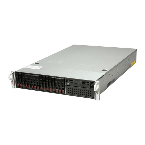
UPER ERVER 2026T-6RFT+/6RF+ User's Manual Figure 6-1. Chassis: Front and Rear Views Slim DVD-ROM Control Panel SATA Drive Bays (4) Control Panel Power Supplies IPMI LAN USB Ports VGA Port PCI Expansion Slots (w/riser card) Mouse/Keyboard Ports COM1 Port 1G Ethernet Ports 10G Ethernet Ports Note: the 10G Ethernet ports are included on the 2026T-6RFT+ only. -
Page 83: System Fans
Chapter 6: Advanced Chassis Setup System Fans Four 8-cm hot-swap fans provide the cooling for the 2026T-6RFT+/6RF+. These fans are located on the front side of the fan bracket. In addition, three optional fans may be placed on the rear side of the fan bracket for cooling redundancy. An air shroud is also included to concentrate the air fl... - Page 84 UPER ERVER 2026T-6RFT+/6RF+ User's Manual Figure 6-3. Installing a Front System Fan Figure 6-4. Installing a Rear System Fan...
-
Page 85: Air Shroud
Chapter 6: Advanced Chassis Setup Air Shroud Figure 6-5. Installing the Air Shroud Air shrouds concentrate airfl ow to maximize fan effi ciency. The SC219 chassis air shroud does not require screws for installation. Installing the Air Shroud 1. Lay the chassis on a fl at, stable surface and remove the chassis cover. 2. -
Page 86: Hard Drive Installation
UPER ERVER 2026T-6RFT+/6RF+ User's Manual Accessing the Drive Bays SATA Drives: Because of their hotswap capability, you do not need to access the inside of the chassis or power down the system to install or replace the SATA drives. Proceed to the next section for instructions. DVD-ROM Drive: For installing/removing a DVD-ROM drive, you will need to gain access to the inside of the 2026T-6RFT+/6RF+ by removing the top cover of the chassis. - Page 87 Chapter 6: Advanced Chassis Setup Figure 6-6. Mounting a Drive in a Carrier Figure 6-7. Removing Hard Drive Tray...
-
Page 88: Hard Drive Backplane
UPER ERVER 2026T-6RFT+/6RF+ User's Manual Hard Drive Backplane The hard drives plug into a backplane that provides power and drive ID. A RAID controller can be used with the backplane to provide data security. The operating system you use must have RAID support to enable the hot-swap capability of the drives. -
Page 89: Power Supply
Chapter 6: Advanced Chassis Setup Power Supply The SuperServer 2026T-6RFT+/6RF+ has a 920 watt redundant power supply consisting of two power modules. Each power supply module has an auto-switching capability, which enables it to automatically sense and operate at a 100V - 240V input voltage. - Page 90 UPER ERVER 2026T-6RFT+/6RF+ User's Manual Figure 6-8. Removing the Power Supply Release Tab 6-10...
-
Page 91: Chapter 7 Bios
Chapter 7: BIOS Chapter 7 BIOS Introduction This chapter describes the AMI BIOS Setup Utility for the X8DTU-6F+/X8DTU-6TF+. The AMI ROM BIOS is stored in a Flash EEPROM and can be easily updated. This chapter describes the basic navigation of the AMI BIOS Setup Utility setup screens. -
Page 92: Main Setup
UPER ERVER 2026T-6RFT+/2026T-6F+ User's Manual Note: For AMI BIOS Recovery, please refer to the AMI BIOS Recovery Instructions posted on our website at http://www.supermicro.com/support/ manuals/. Starting the Setup Utility Normally, the only visible Power-On Self-Test (POST) routine is the memory test. As the memory is being tested, press the <Delete>... - Page 93 Chapter 7: BIOS System Overview: The following BIOS information will display. System Time/System Date Use this option to change the system time and date. Highlight System Time or Sys- tem Date using the arrow keys. Key in new values through the keyboard and press <Enter>.
-
Page 94: Advanced Setup Confi Gurations
UPER ERVER 2026T-6RFT+/2026T-6F+ User's Manual Advanced Setup Confi gurations Use the arrow keys to select Advanced and press <Enter> to access the submenu items. Boot Features Quick Boot If enabled, this feature will skip certain tests during POST to reduce the time needed for system boot. -
Page 95: Processor And Clock Options
Chapter 7: BIOS Hit 'Del' Message Display Select Enabled to display "Press DEL to run Setup" during POST. The options are Enabled and Disabled. Interrupt 19 Capture Interrupt 19 is the software interrupt that handles boot disk functions. When this item is set to Enabled, the ROM BIOS of the host adaptors will "capture"... - Page 96 UPER ERVER 2026T-6RFT+/2026T-6F+ User's Manual • Cache L2: This item displays the size of Cache L2 of the CPU for the moth- erboard. • Cache L3: This item displays the size of Cache L3 of the CPU for the moth- erboard.
- Page 97 Chapter 7: BIOS Intel® Virtualization Technology (Available when supported by the CPU) Select Enabled to use the feature of Virtualization Technology to allow one platform to run multiple operating systems and applications in independent partitions, creat- ing multiple "virtual" systems in one physical computer. The options are Enabled and Disabled.
-
Page 98: Advanced Chipset Control
UPER ERVER 2026T-6RFT+/2026T-6F+ User's Manual C1E Support Select Enabled to use the feature of Enhanced Halt State. C1E signifi cantly reduces the CPU's power consumption by reducing the CPU's clock cycle and voltage during a "Halt State". The options are Disabled and Enabled. Intel®... - Page 99 Chapter 7: BIOS • Memory Reference Code: This item displays the memory reference code for the motherboard. • QPI Reference Code: This item displays the QPI reference code for the moth- erboard. QPI (Quick Path Interconnect) Links Speed QuickPath Interconnect (QPI) is the connection between the CPU and the motherboard's I/O hub.
- Page 100 UPER ERVER 2026T-6RFT+/2026T-6F+ User's Manual Channel Interleave This feature allows the user to confi gure the Memory Interleave settings for an onboard memory channel. The options are 1-way, 2-way, 3-way, 4-way, and 6-way. Bank Interleave This feature allows the user to confi gure the Memory Interleave settings for an onboard memory bank.
- Page 101 Chapter 7: BIOS IOH PCI-E Max Payload Size Some add-on cards perform faster with the coalesce feature, which limits the payload size to 128B; while others, with a payload size of 256B which inhibits the coalesce feature. Please refer to your add-on card user guide for the desired setting. The options are 256B and 128B.
- Page 102 UPER ERVER 2026T-6RFT+/2026T-6F+ User's Manual SATA#1 Confi guration If Compatible is selected, it sets SATA#1 to legacy compatibility mode, while se- lecting Enhanced sets SATA#1 to native SATA mode. The options are Disabled, Compatible and Enhanced. Confi gure SATA#1 as (Not available when SATA#1 Confi guration is disabled) This feature allows the user to select the drive type for SATA#1.
- Page 103 Chapter 7: BIOS LBA/Large Mode LBA (Logical Block Addressing) is a method of addressing data on a disk drive. In the LBA mode, the maximum drive capacity is 137 GB. For drive capacities over 137 GB, your system must be equipped with a 48-bit LBA mode addressing. If not, contact your manufacturer or install an ATA/133 IDE controller card that supports 48-bit LBA mode.
- Page 104 UPER ERVER 2026T-6RFT+/2026T-6F+ User's Manual Select SWDMA2 to allow the BIOS to use Single Word DMA mode 2. It has a data transfer rate of 8.3 MB/s. Select MWDMA0 to allow the BIOS to use Multi Word DMA mode 0. It has a data transfer rate of 4.2 MB/s.
- Page 105 Chapter 7: BIOS Plug & Play OS Selecting Yes allows the OS to confi gure Plug & Play devices. (This is not required for system boot if Plug & Play is supported by your OS.) Select No to allow the AMI BIOS to confi...
- Page 106 UPER ERVER 2026T-6RFT+/2026T-6F+ User's Manual Super IO Device Confi guration Serial Port1 Address/ Serial Port2 Address This option specifi es the base I/O port address and the Interrupt Request address of Serial Port 1 and Serial Port 2. Select Disabled to prevent the serial port from accessing any system resources.
-
Page 107: Hardware Health Monitor
Chapter 7: BIOS to keep Console Redirection active during POST and Boot Loader. The options are Disabled, Boot Loader, and Always. Terminal Type This feature allows the user to select the target terminal type for Console Redirec- tion. The options are ANSI, VT100, and VT-UTF8. VT-UTF8 Combo Key Support A terminal keyboard defi... - Page 108 UPER ERVER 2026T-6RFT+/2026T-6F+ User's Manual CPU 1 Temperature/CPU 2 Temperature/System Temperature This feature displays current temperature readings for the CPU and the System. The following items will be displayed for your reference only: CPU1 Temperature/CPU2 Temperature The CPU thermal technology that reports absolute temperatures (Celsius/Fahr- enheit) has been upgraded to a more advanced feature by Intel in its newer processors.
- Page 109 Chapter 7: BIOS 2. The information provided above is for your reference only. For more information on thermal management, please refer to Intel’s Web site at www.Intel.com. System Temperature: The system temperature will be displayed (in degrees in Celsius and Fahrenheit) as it is detected by the BIOS. Fan 1 ~ Fan 8 Reading This feature displays the fan speed readings from fan interfaces Fan 1 through Fan 8.
- Page 110 UPER ERVER 2026T-6RFT+/2026T-6F+ User's Manual ACPI APIC Support (Available ACPI Aware O/S='Yes') Select Enabled to include the ACPI APIC Table Pointer in the RSDT (Root System Description Table) pointer list. The options are Enabled and Disabled. APIC ACPI SCI IRQ When this item is set to Enabled, APIC ACPI SCI IRQ is supported by the system.
- Page 111 Chapter 7: BIOS BIOS AC[SCLEAN] (Available when Intel TXT(LT) Initialization is enabled) Select Enabled to allow the processor to load an authenticated code (AC) module in an internal memory partition to ensure that the CPU, chipset and all other related components are launched in the same protected environment for trusted-platform computing.
-
Page 112: View Bmc System Event Log
UPER ERVER 2026T-6RFT+/2026T-6F+ User's Manual Execute TPM Command (Available when TCG/TPM Support = 'Yes') Select Enabled to execute TPM commands you've selected. Select Don't Change to keep the current TPM commands without making any changes. Select Dis- abled to abandon the changes you have made on TPM commands. The options are Enabled, Disabled and Don't Change. - Page 113 Chapter 7: BIOS • SEL Record Type • Event Timestamp • Generator ID • Event Message Format Ver. • Event Sensor Type • Event Sensor Number, • Event Dir Type • Event Data. Clear BMC System Event Log Clear BMC System Log now Select OK and press the <Enter>...
- Page 114 UPER ERVER 2026T-6RFT+/2026T-6F+ User's Manual assigned to the client can be reassigned to a new client. Select Static (Static Allocation) to allow the host server to allocate an IP address based on a table containing MAC Address/IP Address pairs that are manually entered (probably by a network administrator).
-
Page 115: Security Settings
Chapter 7: BIOS after an operating system failure is detected. The options are [5 Min], [1 Min], [30 Sec], and [10 Sec]. DMI Event Log Confi guration View Event Log Use this option to view the System Event Log. Mark All Events as Read This option marks all events as read. - Page 116 UPER ERVER 2026T-6RFT+/2026T-6F+ User's Manual Supervisor Password This item indicates if a Supervisor password has been entered for the system. "Not Installed" means a Supervisor password has not been used. User Password This item indicates if a user password has been entered for the system. "Not In- stalled"...
-
Page 117: Boot Confi Guration
Chapter 7: BIOS Boot Confi guration Use this feature to confi gure boot settings. Boot Device Priority This feature allows the user to specify the sequence of priority for the Boot Device. The settings are 1st boot device, 2nd boot device, 3rd boot device, 4th boot device, 5th boot device and Disabled. -
Page 118: Exit Options
UPER ERVER 2026T-6RFT+/2026T-6F+ User's Manual Exit Options Select the Exit tab from the AMI BIOS Setup Utility screen to enter the Exit BIOS Setup screen. Save Changes and Exit When you have completed the system confi guration changes, select this option to leave the BIOS Setup Utility and reboot the computer, so the new system con- fi... - Page 119 Chapter 7: BIOS Load Fail-Safe Defaults To set this feature, select Load Fail-Safe Defaults from the Exit menu and press <Enter>. The Fail-Safe settings are designed for maximum system stability, but not for maximum performance. 7-29...
- Page 120 UPER ERVER 2026T-6RFT+/2026T-6F+ User's Manual Notes 7-30...
-
Page 121: Appendix A Bios Error Beep Codes
Appendix A: BIOS Error Beep Codes Appendix A BIOS Error Beep Codes During the POST (Power-On Self-Test) routines, which are performed each time the system is powered on, errors may occur. Non-fatal errors are those which, in most cases, allow the system to continue the boot-up process. - Page 122 UPER ERVER 1026T-6RFT+/1026T-6F+ User's Manual Notes...
-
Page 123: Appendix B System Specifi Cations
Appendix B: System Specifi cations Appendix B System Specifi cations Processors Single or dual Intel® 5500/5600 Series processors in LGA1366 sockets Note: Please refer to our web site for a complete listing of supported processors. Chipset Intel 5520/ICH10R chipset BIOS 32 Mb AMI®... - Page 124 UPER ERVER 2026T-6RFT+/2026T-6F+ User's Manual Serverboard 2026T-6RFT+: X8DTU-6TF+ (Proprietary form factor) 2026T-6RF+: X8DTU-6F+ (Proprietary form factor) Dimensions: 16.5 x 12.8 in (419 x 325 mm) Chassis SC219A-R920U (2U rackmount) Dimensions: (WxHxD) 17.2 x 3.5 x 26.93 in. (437 x 89 x 684 mm) Weight Gross Weight: 52 lbs.
- Page 125 Appendix B: System Specifi cations Regulatory Compliance Electromagnetic Emissions: FCC Class A, EN 55022 Class A, EN 61000-3-2/-3-3, CISPR 22 Class A Electromagnetic Immunity: EN 55024/CISPR 24, (EN 61000-4-2, EN 61000-4-3, EN 61000-4-4, EN 61000-4-5, EN 61000-4-6, EN 61000-4-8, EN 61000-4-11) Safety: CSA/EN/IEC/UL 60950-1 Compliant, UL or CSA Listed (USA and Canada), CE Marking (Europe) California Best Management Practices Regulations for Perchlorate Materials:...
- Page 126 UPER ERVER 2026T-6RFT+/2026T-6F+ User's Manual (continued from front) The products sold by Supermicro are not intended for and will not be used in life support systems, medical equipment, nuclear facilities or systems, aircraft, aircraft devices, aircraft/emergency com- munication devices or other critical systems whose failure to perform be reasonably expected to result in signifi...
Need help?
Do you have a question about the SUPERSERVER 2026T-6RFT+ and is the answer not in the manual?
Questions and answers