Table of Contents
Advertisement
Quick Links
Advertisement
Table of Contents

Related Manuals for Supero SUPERSERVER 2027TR-D70RF


Summary of Contents for Supero SUPERSERVER 2027TR-D70RF
- Page 1 UPER ® UPER ERVER ® 2027TR-D70RF 2027TR-D70RF+ USER’S MANUAL Revision 1.0a...
- Page 2 The information in this User’s Manual has been carefully reviewed and is believed to be accurate. The vendor assumes no responsibility for any inaccuracies that may be contained in this document, makes no commitment to update or to keep current the information in this manual, or to notify any person or organization of the updates.
- Page 3 Preface Preface About this Manual This manual is written for professional system integrators and PC technicians. It provides information for the installation and use of the SuperServer 2027TR-D70RF(+). Installation and maintainance should be performed by experienced technicians only. Please refer to the 2027TR-D70RF(+) server specifications page on our Web site for updates on supported memory, processors and operating systems (http://www.
-
Page 4: Table Of Contents
UPER ERVER 2027TR-D70RF(+) Manual Contents Chapter 1 Introduction ................1-1 Overview ......................1-1 Serverboard Features ..................1-2 Processors ...................... 1-2 Memory ......................1-2 SAS/SATA......................1-2 PCI Expansion Slots ..................1-3 Onboard Controllers/Ports ................1-3 Graphics Controller ..................1-3 Other Features ....................1-3 Server Chassis Features ................ - Page 5 Preface Mechanical Loading ................... 2-3 Circuit Overloading ..................2-3 Reliable Ground ..................2-3 Installing the System into a Rack ..............2-4 Separating the Sections of the Rack Rails ............. 2-4 Locking Tabs ....................2-5 Releasing the Inner Rail ................. 2-5 Installing The Inner Rails on the Chassis ............
- Page 6 UPER ERVER 2027TR-D70RF(+) Manual Processor and Heatsink Installation..............5-3 Installing a Passive CPU Heatsink ..............5-7 Removing the Passive Heatsink ..............5-7 Installing Memory .................... 5-8 Memory Support ....................5-8 DIMM Module Population Configuration ..........5-10 Adding PCI Expansion Cards ............... 5-12 Motherboard Details ..................
- Page 7 Preface 6-13 Power Supply ....................6-22 Power Supply Replacement ................6-22 Chapter 7 BIOS ..................7-1 Introduction ...................... 7-1 Starting BIOS Setup Utility ................7-1 How To Change the Configuration Data ............7-1 Starting the Setup Utility ................. 7-2 Main Setup ...................... 7-2 Advanced Settings Menu ................
- Page 8 UPER ERVER 2027TR-D70RF(+) Manual Contacting Supermicro Headquarters Address: Super Micro Computer, Inc. 980 Rock Ave. San Jose, CA 95131 U.S.A. Tel: +1 (408) 503-8000 Fax: +1 (408) 503-8008 Email: marketing@supermicro.com (General Information) support@supermicro.com (Technical Support) Web Site: www.supermicro.com Europe Address: Super Micro Computer B.V.
-
Page 9: Chapter 1 Introduction
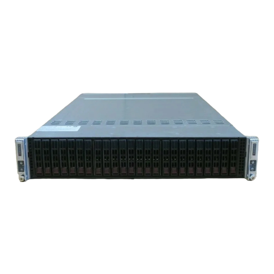
Chapter 1 Introduction Overview The SuperServer 2027TR-D70RF(+) is a high-end server comprised of two main subsystems: the SC217HD-R1K28MB 2U server chassis and the X9DRT-HF(+) dual processor serverboard in two hot-swap nodes. Please refer to our web site for information on operating systems that have been certified for use with the system (www.supermicro.com). -
Page 10: Serverboard Features
6 Gb/s SAS2 (Serial Attached SCSI) /SATA3 subsystem for each node. The system has either RAID 0, 1 and 10 support for the SuperServer 2027TR-D70RF(+) server. The SAS/SATA drives are hot-swappable units. Note: The operating system you use must have RAID support to enable the... -
Page 11: Pci Expansion Slots
Chapter 1: Introduction PCI Expansion Slots Each node has one available PCIe 3.0 x8 Slot for a proprietary Micro LP card (CPU1 Slot2). Onboard Controllers/Ports The I/O ports include a VGA (monitor) port, two USB 2.0 ports (an additional internal USB header and one Type A USB connector are included on the serverboard), an IPMI 2.0 dedicated LAN port and two Ethernet ports. -
Page 12: Front Control Panel
SuperServer 2027TR-D70RF(+) USER'S MANUAL Front Control Panel Each control panel on the chassis front handle provides system monitoring and control for one server node. LEDs indicate system power, HDD activity, network activity, system overheat and power supply failure. A main power button and a system reset button are also included. -
Page 13: Manageability Engine (Me)
Chapter 1: Introduction Manageability Engine (ME) The Manageability Engine, which is an ARC controller embedded in the IOH (I/O Hub), provides Server Platform Services (SPS) to your system. The services provided by SPS are different from those proveded by the ME on client platforms. - Page 14 SuperServer 2027TR-D70RF(+) USER'S MANUAL Figure 1-1. Intel Intel C602 Chipset: System Block Diagram Note: This is a general block diagram and may not exactly repre- sent the features on your motherboard. See the previous pages for the actual specifications of your motherboard. This block diagram is intended for your reference only.
-
Page 15: Contacting Supermicro
Chapter 1: Introduction Contacting Supermicro Headquarters Address: Super Micro Computer, Inc. 980 Rock Ave. San Jose, CA 95131 U.S.A. Tel: +1 (408) 503-8000 Fax: +1 (408) 503-8008 Email: marketing@supermicro.com (General Information) support@supermicro.com (Technical Support) Web Site: www.supermicro.com Europe Address: Super Micro Computer B.V. Het Sterrenbeeld 28, 5215 ML 's-Hertogenbosch, The Netherlands Tel:... -
Page 16: Twin: System Notes
SAS/SATA Backplane/Drives As a system, the SuperServer 2027TR-D70RF(+) supports the use of twenty-four (24) 2.5" SAS/SATA drives. A single SAS/SATA backplane works to apply system- based control for power and fan speed functions, yet at the same time logically connects a set of twelve SAS/SATA drives to each serverboard. -
Page 17: Chapter 2 Server Installation
Chapter 2: Server Installation Chapter 2 Server Installation Overview This chapter provides a quick setup checklist to get your SuperServer 2027TR-D70RF(+) up and running. Following these steps in the order given should enable you to have the system operational within a minimum amount of time. This quick setup assumes that your system has come to you with the processors and memory preinstalled. -
Page 18: Warnings And Precautions
SUPERSERVER 2027TR-D70RF(+) USER'S MANUAL • This product is for installation only in a Restricted Access Location (dedicated equipment rooms, service closets and the like). • This product is not suitable for use with visual display work place devices acccording to §2 of the the German Ordinance for Work with Visual Display Units. -
Page 19: Rack Mounting Considerations
Chapter 2: Server Installation Rack Mounting Considerations Ambient Operating Temperature If installed in a closed or multi-unit rack assembly, the ambient operating temperature of the rack environment may be greater than the ambient temperature of the room. Therefore, consideration should be given to installing the equipment in an environment compatible with the manufacturer’s maximum rated ambient temperature (Tmra). -
Page 20: Installing The System Into A Rack
SUPERSERVER 2027TR-D70RF(+) USER'S MANUAL Installing the System into a Rack This section provides information on installing the chassis into a rack unit with the rails provided. There are a variety of rack units on the market, which may mean that the assembly procedure will differ slightly from the instructions provided. You should also refer to the installation instructions that came with the rack unit you are using. -
Page 21: Locking Tabs
Chapter 2: Server Installation Locking Tabs Each inner rail has a locking tab. This tab locks the chassis into place when installed and pushed fully into the rack. These tabs also lock the chassis in place when fully extended from the rack. This prevents the server from coming completely out of the rack when when the chassis is pulled out for servicing. -
Page 22: Installing The Inner Rails On The Chassis
SUPERSERVER 2027TR-D70RF(+) USER'S MANUAL Installing The Inner Rails on the Chassis Installing the Inner Rails (Figure 2-3 and Figure 2-4) 1. Confirm that the left and right inner rails have been correctly identified. 2. Place the inner rail firmly against the side of the chassis, aligning the hooks on the side of the chassis with the holes in the inner rail. -
Page 23: Installing The Outer Rails On The Rack
Chapter 2: Server Installation Installing the Outer Rails on the Rack Installing the Outer Rails (Figure 2-5) 1. Press upward on the locking tab at the rear end of the middle rail. 2. Push the middle rail back into the outer rail. 3. -
Page 24: Standard Chassis Installation
SUPERSERVER 2027TR-D70RF(+) USER'S MANUAL Standard Chassis Installation Installing the Chassis into a Rack (Figure 2-6) 1. Confirm that the inner rails are properly installed on the chassis. 2. Confirm that the outer rails are correctly installed on the rack. 3. Pull the middle rail out from the front of the outer rail and make sure that the ball-bearing shuttle is at the front locking position of the middle rail. -
Page 25: Optional Quick Installation Method
Chapter 2: Server Installation 7. If necessary for security purposes, use screws to secure the chassis handles to the front of the rack. Optional Quick Installation Method The following quick installation method may be used to install the chassis onto a rack. - Page 26 SUPERSERVER 2027TR-D70RF(+) USER'S MANUAL Figure 2-7. Accessing the Inside of the System Remove two screws Check Ventilation Openings 3. Remove the two screws which secure the top cover onto the chassis as shown above. 4. Lift the top cover up and off the chassis.
-
Page 27: Checking The Drive Bay Setup
Chapter 2: Server Installation 3. If desired, you can install add-on cards to the system. See Chapter 5 for details on installing PCI expansion cards. 4. Make sure all power and data cables are properly connected and not blocking the chassis airflow. Also make sure that no cables are positioned in front of the fans. - Page 28 SUPERSERVER 2027TR-D70RF(+) USER'S MANUAL Notes 2-12...
-
Page 29: Chapter 3 System Interface
Chapter 3: System Interface Chapter 3 System Interface Overview The chassis includes: • Control panels on the front that include power buttons and status monitoring lights • Status lights on externally accessible hard drives • Status lights for the power supply The control panels are located on the front, outside edges of the chassis. -
Page 30: Control Panel Buttons
SUPERSERVER 2027TR-D70RF(+) USER'S MANUAL Control Panel Buttons Power: The main power switch is used to apply or remove power from the power supply to the node. Turning off system power with this button removes the main power but maintains standby power. To perform many maintenance tasks, you must unplug system before servicing.. -
Page 31: Drive Carrier Leds
Chapter 3: System Interface Information LED: Alerts operator of several states, as noted in the table below. Information LED Status Description An overheat condition has occured. Continuously on and red (This may be caused by cable congestion.) Blinking red (1Hz) Fan failure, check for an inoperative fan. - Page 32 SUPERSERVER 2027TR-D70RF(+) USER'S MANUAL Notes...
-
Page 33: Chapter 4 Standardized Warning Statements For Ac Systems
Chapter 4: Warning Statements for AC Systems Chapter 4 Standardized Warning Statements for AC Systems About Standardized Warning Statements The following statements are industry standard warnings, provided to warn the user of situations which have the potential for bodily injury. Should you have questions or experience difficulty, contact Supermicro's Technical Support department for assistance. - Page 34 SUPERSERVER 2027TR-D70RF(+) User's Manual Warnung WICHTIGE SICHERHEITSHINWEISE Dieses Warnsymbol bedeutet Gefahr. Sie befinden sich in einer Situation, die zu Verletzungen führen kann. Machen Sie sich vor der Arbeit mit Geräten mit den Gefahren elektrischer Schaltungen und den üblichen Verfahren zur Vorbeugung vor Unfällen vertraut.
- Page 35 Chapter 4: Warning Statements for AC Systems جسذٌة اصابة ًتتسبب ف حالة ٌوكي أى ًاًك ف خطز ًٌٌع هذا الزهز !تحذٌز الذوائز بالوخاطز الٌاجوة عي ي على علن ، ك هعذات تعول على أي قبل أى الكهزبائٍة حىادث أي وقىع وٌع...
-
Page 36: Installation Instructions
SUPERSERVER 2027TR-D70RF(+) User's Manual Installation Instructions Warning! Read the installation instructions before connecting the system to the power source. 設置手順書 システムを電源に接続する前に、 設置手順書をお読み下さい。 警告 将此系统连接电源前,请先阅读安装说明。 警告 將系統與電源連接前,請先閱讀安裝說明。 Warnung Vor dem Anschließen des Systems an die Stromquelle die Installationsanweisungen lesen. ¡Advertencia! Lea las instrucciones de instalación antes de conectar el sistema a la red de alimentación. -
Page 37: Circuit Breaker
Chapter 4: Warning Statements for AC Systems Circuit Breaker Warning! This product relies on the building's installation for short-circuit (overcurrent) protection. Ensure that the protective device is rated not greater than: 250 V, 20 A. サーキッ ト ・ ブレーカー この製品は、 短絡 (過電流) 保護装置がある建物での設置を前提としています。 保護装置の定格が250 V、... -
Page 38: Power Disconnection Warning
SUPERSERVER 2027TR-D70RF(+) User's Manual 경고! 이 제품은 전원의 단락(과전류)방지에 대해서 전적으로 건물의 관련 설비에 의존합니다. 보호장치의 정격이 반드시 250V(볼트), 20A(암페어)를 초과하지 않도록 해야 합니다. Waarschuwing Dit product is afhankelijk van de kortsluitbeveiliging (overspanning) van uw electrische installatie. Controleer of het beveiligde aparaat niet groter gedimensioneerd is dan 220V, 20A. - Page 39 Chapter 4: Warning Statements for AC Systems ¡Advertencia! El sistema debe ser disconnected de todas las fuentes de energía y del cable eléctrico quitado de los módulos de fuente de alimentación antes de tener acceso el interior del chasis para instalar o para quitar componentes de sistema. Attention Le système doit être débranché...
-
Page 40: Equipment Installation
SUPERSERVER 2027TR-D70RF(+) User's Manual Equipment Installation Warning! Only trained and qualified personnel should be allowed to install, replace, or service this equipment. 機器の設置 トレーニングを受け認定された人だけがこの装置の設置、 交換、 またはサービスを許可 されています。 警告 只有经过培训且具有资格的人员才能进行此设备的安装、更换和维修。 警告 只有經過受訓且具資格人員才可安裝、更換與維修此設備。 Warnung Das Installieren, Ersetzen oder Bedienen dieser Ausrüstung sollte nur geschultem, qualifiziertem Personal gestattet werden. -
Page 41: Restricted Area
Chapter 4: Warning Statements for AC Systems Waarschuwing Deze apparatuur mag alleen worden geïnstalleerd, vervangen of hersteld door geschoold en gekwalificeerd personeel. Restricted Area Warning! This unit is intended for installation in restricted access areas. A restricted access area can be accessed only through the use of a special tool, lock and key, or other means of security. -
Page 42: Battery Handling
SUPERSERVER 2027TR-D70RF(+) User's Manual אזור עם גישה מוגבלת !אזהרה יש להתקין את היחידה באזורים שיש בהם הגבלת גישה. הגישה ניתנת בעזרת .)'כלי אבטחה בלבד (מפתח, מנעול וכד محظورة مناطق ٍنتركُبها ف هذه انىحذة تخصيص تم ،أداة خاصت من خالل استخذاو... - Page 43 Chapter 4: Warning Statements for AC Systems Warnung Bei Einsetzen einer falschen Batterie besteht Explosionsgefahr. Ersetzen Sie die Batterie nur durch den gleichen oder vom Hersteller empfohlenen Batterietyp. Entsorgen Sie die benutzten Batterien nach den Anweisungen des Herstellers. Attention Danger d'explosion si la pile n'est pas remplacée correctement. Ne la remplacer que par une pile de type semblable ou équivalent, recommandée par le fabricant.
-
Page 44: Redundant Power Supplies (If Applicable To Your System)
SUPERSERVER 2027TR-D70RF(+) User's Manual Redundant Power Supplies (if applicable to your system) Warning! This unit might have more than one power supply connection. All connections must be removed to de-energize the unit. 冗長電源装置 このユニッ トは複数の電源装置が接続されている場合があります。 ユニッ トの電源を切るためには、 すべての接続を取り外さなければなりません。 警告 此部件连接的电源可能不止一个,必须将所有电源断开才能停止给该部件供电。... -
Page 45: Backplane Voltage (If Applicable To Your System)
Chapter 4: Warning Statements for AC Systems امداد الطاقة بوحدات عدة اتصاالت جهاز ال يكون لهذا قد الكهرباء عن وحدة ال لعسل كافة االتصاالت يجب إزالة 경고! 이 장치에는 한 개 이상의 전원 공급 단자가 연결되어 있을 수 있습니다. 이 장치에... -
Page 46: Comply With Local And National Electrical Codes
SUPERSERVER 2027TR-D70RF(+) User's Manual מתח בפנל האחורי !הרה אז קיימת סכנת מתח בפנל האחורי בזמן תפעול המערכת. יש להיזהר במהלך .העבודה اللىحة أوالطاقة المىجىدة على التيار الكهزبائي مه خطز هناك هذا الجهاس خدمة كه حذرا عند يعمل النظام عندما يكىن... -
Page 47: Product Disposal
Chapter 4: Warning Statements for AC Systems Attention L'équipement doit être installé conformément aux normes électriques nationales et locales. תיאום חוקי החשמל הארצי !אזהרה הציוד חייבת להיות תואמת לחוקי החשמל המקומיים והארציים התקנת المتعلقة المحلية والىطىية قىاويه يجب أن يمتثل لل الكهربائية... -
Page 48: Hot Swap Fan Warning (If Applicable To Your System)
SUPERSERVER 2027TR-D70RF(+) User's Manual ¡Advertencia! Al deshacerse por completo de este producto debe seguir todas las leyes y reglamentos nacionales. Attention La mise au rebut ou le recyclage de ce produit sont généralement soumis à des lois et/ou directives de respect de l'environnement. Renseignez-vous auprès de l'organisme compétent. - Page 49 Chapter 4: Warning Statements for AC Systems 警告 當您從機架移除風扇裝置,風扇可能仍在轉動。小心不要將手指、螺絲起子和其他 物品太靠近風扇。 Warnung Die Lüfter drehen sich u. U. noch, wenn die Lüfterbaugruppe aus dem Chassis genommen wird. Halten Sie Finger, Schraubendreher und andere Gegenstände von den Öffnungen des Lüftergehäuses entfernt. ¡Advertencia! Los ventiladores podran dar vuelta cuando usted quite ell montaje del ventilador del chasis.
-
Page 50: Power Cable And Ac Adapter
SUPERSERVER 2027TR-D70RF(+) User's Manual Power Cable and AC Adapter Warning! When installing the product, use the provided or designated connection cables, power cables and AC adaptors. Using any other cables and adaptors could cause a malfunction or a fire. Electrical Appliance and Material Safety Law prohibits the use of UL or CSA -certified cables (that have UL/CSA shown on the code) for any other electrical devices than products designated by Supermicro only. - Page 51 Chapter 4: Warning Statements for AC Systems Attention Lors de l'installation du produit, utilisez les bables de connection fournis ou désigné. L'utilisation d'autres cables et adaptateurs peut provoquer un dysfonctionnement ou un incendie. Appareils électroménagers et de loi sur la sécurité Matériel interdit l'utilisation de UL ou CSA câbles certifiés qui ont UL ou CSA indiqué...
- Page 52 SUPERSERVER 2027TR-D70RF(+) User's Manual Notes 4-20...
-
Page 53: Chapter 5 Advanced Motherboard Setup
Chapter 5: Advanced Motherboard Setup Chapter 5 Advanced Motherboard Setup This chapter covers the steps required to install the X9DRT-HF(+) motherboard into the chassis, connect the data and power cables and install add-on cards. All motherboard jumpers and connections are also described. A layout and quick reference chart are included in this chapter for your reference. -
Page 54: Rear I/O Ports
SUPERSERVER 2027TR-D70RF(+) USER'S MANUAL Notes: 1. For the latest CPU/Memory updates, please refer to the Supermicro website at http://www.supermicro.com/products/motherboard/. 2. Use only the correct type of onboard CMOS battery as specified by the manufacturer. Do not install the onboard battery upside down to avoid possible explosion. -
Page 55: Processor And Heatsink Installation
Chapter 5: Advanced Motherboard Setup Processor and Heatsink Installation Caution! When handling the processor package, avoid placing direct pressure on the label area. Always connect the power cord last, and always remove it before adding, removing or changing any hardware components. Make sure that you install the processor into the CPU socket before you install the CPU heatsink. - Page 56 SUPERSERVER 2027TR-D70RF(+) USER'S MANUAL 2. Press the second load lever labeled 'Close 1st' to release the load plate that covers the CPU socket from its locking position. Press down on Load the Pull lever away Lever labeled 'Close 1st' from the socket 3.
- Page 57 Chapter 5: Advanced Motherboard Setup 5. Use your thumb and index finger to hold the CPU on its edges. Align the CPU keys, which are semi-circle cutouts, against the socket keys. Socket Keys CPU Keys 6. Once they are aligned, carefully lower the CPU straight down into the socket. (Do not drop the CPU on the socket.
- Page 58 SUPERSERVER 2027TR-D70RF(+) USER'S MANUAL 7. With the CPU inside the socket, inspect the four corners of the CPU to make sure that the CPU is properly installed. 8. Close the load plate with the CPU inside the socket. Lock the lever labeled 'Close 1st' first, then lock the lever labeled 'Open 1st' second.
-
Page 59: Installing A Passive Cpu Heatsink
Chapter 5: Advanced Motherboard Setup Installing a Passive CPU Heatsink 1. Apply the proper amount of thermal grease to the heatsink. 2. Place the heatsink on top of the CPU so that the four mounting holes on the heatsink are aligned with those on the retention mechanism. 3. -
Page 60: Installing Memory
SUPERSERVER 2027TR-D70RF(+) USER'S MANUAL Installing Memory Memory Support • For 2027TR-D70RF, memory capacity is 8 sockets supporting up to 512GB ECC LRDIMM, or up to 256GB ECC Registered memory (RDIMM). • For 2027TR-D70RF+, memory capacity is 16 sockets supporting up to 1TB ECC LRDIMM, or up to 512GB ECC Registered memory (RDIMM). - Page 61 Chapter 5: Advanced Motherboard Setup Figure 5-2. Installing DIMM into Slot To Install: Insert Notch Notch module vertically and press down until it snaps into place. Front View Pay attention to the alignment notch at the bottom. Note: Notch should align with To Remove: Use the receptive key point on the slot.
-
Page 62: Dimm Module Population Configuration
SUPERSERVER 2027TR-D70RF(+) USER'S MANUAL DIMM Module Population Configuration For memory to work properly, follow the tables below for memory installation: Intel E5-2600 Series Processor UDIMM Memory Support Ranks Memory Capacity Speed (MT/s) and Voltage Validated by Slot per Per DIMM... - Page 63 Chapter 5: Advanced Motherboard Setup Intel E5-2600 Series Processor LRDIMM Memory Support Ranks Per Memory Speed (MT/s) and Voltage DIMM & Capacity Validated by Slot per Channel Data Width Per DIMM (SPC) and DIMM Per Channel (DPC) (See the 1 Slot Per 2 Slots Per Note Below) Channel...
-
Page 64: Adding Pci Expansion Cards
SUPERSERVER 2027TR-D70RF(+) USER'S MANUAL Adding PCI Expansion Cards Each node accepts one MicroLP expansion card. See Chapter 6 for details and installation. 5-12... -
Page 65: Motherboard Details
Chapter 5: Advanced Motherboard Setup Motherboard Details USB0 USB1 LAN1 IPMI_LAN LAN2 Battery FAN4 FAN3 JPME1 COM1 JPME2 LAN CTRL JBT1 Intel PCH CPU1 X9DRT-HF+ Rev. 1.02 CPU2 CPU2 Figure 5-3. X9DRT-HF+ Motherboard Layout (not drawn to scale) 5-13... - Page 66 SUPERSERVER 2027TR-D70RF(+) USER'S MANUAL X9DRT-HF(+) Quick Reference Jumper Description Default Setting JBT1 Clear CMOS See Section 5-8 JPB1 BMC Enabled Pins 1-2 (Enabled) JPG1 VGA Enabled Pins 1-2 (Enabled) JPL1 Ethernet GLAN1/GLAN2 Enable Pins 1-2 (Enabled) JWD1 Watch Dog Pins 1-2 (Reset)
-
Page 67: Connector Definitions
Chapter 5: Advanced Motherboard Setup Connector Definitions Ethernet LAN Ports Two Gigabit Ethernet ports (LAN1/2) are located on the I/O backplane on the motherboard. In addition, an IPMI Dedicated LAN is located above USB 0/1 ports on the backplane to provide KVM support for IPMI 2.0. - Page 68 SUPERSERVER 2027TR-D70RF(+) USER'S MANUAL Unit Identifier Switches UID Switch Two Unit Identifier (UID) Switches and Pin# Definition two LED Indicators are located on the Ground motherboard. The Front Panel UID Ground Switch is located at Pin 16 on JF2. The...
- Page 69 Chapter 5: Advanced Motherboard Setup TPM Header/Port 80 TPM/Port 80 Header (JTPM1) Pin Definitions A Trusted Platform Module/Port 80 Pin# Definition Pin# Definition header is located at JTPM1 to provide LCLK TPM support and Port 80 connection. LFRAME# <(KEY)> Use this header to enhance system LRESET# +5V (X) performance and data security.
-
Page 70: Jumper Settings
SUPERSERVER 2027TR-D70RF(+) USER'S MANUAL Jumper Settings Connector Pins Explanation of Jumpers To modify the operation of the motherboard, Jumper jumpers can be used to choose between optional settings. Jumpers create shorts between two pins to change the function Setting of the connector. Pin 1 is identified with a square solder pad on the printed circuit board. - Page 71 Chapter 5: Advanced Motherboard Setup Watch Dog Enable/Disable Watch Dog (JWD1) Jumper Settings Watch Dog (JWD1) is a system monitor Jumper Setting Definition that can reboot the system when a Pins 1-2 Reset (default) software application hangs. Close Pins Pins 2-3 1-2 to reset the system if an application hangs.
-
Page 72: Onboard Indicators
SUPERSERVER 2027TR-D70RF(+) USER'S MANUAL Onboard Indicators GLAN LEDs LAN LED (Connection Speed Indicator) The Gigabit LAN ports are located on LED Color Definition the IO Backplane on the motherboard. 10 MHz On each Gb LAN port, one LED blinks Green... - Page 73 Chapter 5: Advanced Motherboard Setup HDD/SATA LED (LE3) HDD/SATA LED (LE3) Settings An HDD/SATA LED Indicator is located Status Definition at LE3 on the motherboard. This LED HDD/SATA Connected indicates the status of hard drive activities No connection or SATA activities supported by the South Bridge.
-
Page 74: 5-10 Pci-Express And Serial Ata Connections
SUPERSERVER 2027TR-D70RF(+) USER'S MANUAL 5-10 PCI-Express and Serial ATA Connections PCI-Express 3.0 x8 Micro LP Card Slot One PCIe 3.0 x8 Slot for proprietary Micro LP Card (CPU1 Slot2) is located on the serverboard. Refer to the layout on page 5-14 for the location. -
Page 75: 5-11 Installing Software
Chapter 5: Advanced Motherboard Setup 5-11 Installing Software The Supermicro ftp site contains drivers and utilities for your system at ftp://ftp. supermicro.com. Some of these must be installed, such as the chipset driver. After accessing the ftp site, go into the CDR_Images directory and locate the ISO file for your motherboard. -
Page 76: Superdoctor Iii
SUPERSERVER 2027TR-D70RF(+) USER'S MANUAL SuperDoctor III The SuperDoctor III program is a web-based management tool that supports ® remote management capability. It includes Remote and Local Management tools. The local management is called SD III Client. The SuperDoctor III program allows you to monitor the environment and operations of your system. - Page 77 Chapter 5: Advanced Motherboard Setup Figure 5-6. SuperDoctor III Interface Display Screen (Remote Control) Note: The SuperDoctor III program and User’s Manual can be downloaded from the Supermicro web site at http://www.supermicro.com/products/accessories/ software/SuperDoctorIII.cfm. For Linux, we recommend that you use the SuperoDoctor II application instead.
-
Page 78: 5-12 Onboard Battery
SUPERSERVER 2027TR-D70RF(+) USER'S MANUAL 5-12 Onboard Battery Caution: There is a danger of explosion if the onboard battery is installed upside down, which will reverse its polarites (see Figure 5-7). This battery must be replaced only with the same or an equivalent type recommended by the manufacturer (CR2032). -
Page 79: Chapter 6 Advanced Chassis Setup
Chapter 6: Advanced Chassis Setup Chapter 6 Advanced Chassis Setup This chapter covers the steps required to install components and perform maintenance on the SC217HD-R1K28MB chassis. For component installation, follow the steps in the order given to eliminate the most common problems encountered. -
Page 80: Control Panel
SUPERSERVER 2027TR-D70RF(+) USER'S MANUAL Figure 6-1. Chassis Front View Node A Control Panel Node B Control Panel Hard Drives Figure 6-2. Chassis Rear View Power Supply LAN Ports VGA Port USB Ports Control Panel Each control panel on the front of the chassis must be connected to the JF2 connector on its associated serverboard to provide you with system control buttons and status indicators. -
Page 81: Accessing The Inside Of The System
Chapter 6: Advanced Chassis Setup Accessing the inside of the System Before operating the SC217HD chassis for the first time, it is important to remove the protective film over the cover of the chassis, in order to allow for proper ventilation and cooling. -
Page 82: Installing The Air Shrouds
SUPERSERVER 2027TR-D70RF(+) USER'S MANUAL Installing the Air Shrouds Air Shrouds Air shrouds concentrate airflow to maximize fan efficiency. The SC217 chassis requires air shrouds for each node. Air shrouds vary depending upon the serverboard used. See the illustrations below. Installing an Air Shroud (Figure 6-4) 1. -
Page 83: Checking The Airflow
Chapter 6: Advanced Chassis Setup Checking the Airflow Checking Airflow 1. Make sure there are no objects obstructing the airflow in and out of the chassis. In addition, if you are using a front bezel, make sure the bezel's filter is replaced periodically. - Page 84 SUPERSERVER 2027TR-D70RF(+) USER'S MANUAL Changing a System Fan 1. If necessary, open the chassis while the system is running to determine which fan has failed. (Never run the server for an extended period of time with the chassis cover open.) After determining which fan needs to be replaced, power down the system and disconnect the power cord from the rear of both power supplies.
- Page 85 Chapter 6: Advanced Chassis Setup Figure 6-6. Replacing a System Fan in the Fan Housing...
-
Page 86: Removing And Installing The Backplane
SUPERSERVER 2027TR-D70RF(+) USER'S MANUAL Removing and Installing the Backplane The SC217HD chassis backplane is located behind the hard drives and in front of the front system fans. Although backplane failure rarely occurs, in the event of a backplane failure, follow the instructions below. - Page 87 Chapter 6: Advanced Chassis Setup 8. Loosen the three screws in the spring bar, located on the floor of the chassis, indicated by the arrows below (Figure 6-8). Figure 6-8: Loosening the Spring Bar Screws in the Floor of the Chassis 9.
-
Page 88: Installing The Backplane
SUPERSERVER 2027TR-D70RF(+) USER'S MANUAL Installing the Backplane Installing the Backplane into the Chassis (Figure 6-10) 1. Ensure that all of the hard drive carriers have been removed from the bays in the front of the chassis and that the spring bar has been loosened as directed in the previous section. -
Page 89: Installing The Serverboard
Chapter 6: Advanced Chassis Setup Installing the Serverboard I/O Shield The I/O shield (Figure 6-11) holds the serverboard ports in place. The I/O shield does not require installation. Figure 6-11. I/O Shield Placement I/O Shields Compatible Serverboards Most Supermicro wirelessTwin series serverboards are compatible with the SC217HD chassis. - Page 90 SUPERSERVER 2027TR-D70RF(+) USER'S MANUAL Installing the Serverboard (Figure 6-12) 1. Review the documentation that came with your serverboard. Become familiar with component placement, requirements, cautions, and cable connections. 2. Remove the serverboard node from the back of the chassis. It is not necessary to power down the system.
-
Page 91: Node Installation/Removal
Chapter 6: Advanced Chassis Setup Node Installation/Removal As with any server system, power must be removed from the serverboard when upgrading or installing memory or processors. In the 2U Twin server, the serverboards (nodes) are capable of being hot-swapped from the chassis, allowing one to be powered down for servicing while the other continues operating. - Page 92 SUPERSERVER 2027TR-D70RF(+) USER'S MANUAL Figure 6-13. Removing a System Node 6-14...
-
Page 93: 6-10 Installing And Replacing The Adapter Card
Chapter 6: Advanced Chassis Setup 6-10 Installing and Replacing the Adapter Card Adapter cards (Figure 6-14) provide hot-swappable functionality to the chassis. Figure 6-14. Adapter Card Installation Adapter Card Node Drawer Ten Screws Removing the Adapter Card 1. Remove the node from the back of the chassis. It is not necessary to power down the system. -
Page 94: 6-11 Pci Slot Setup
SUPERSERVER 2027TR-D70RF(+) USER'S MANUAL 6-11 PCI Slot Setup The 2027TR-D70RF(+) server supports one Micro low-profile (MicroLP--proprietary) PCI-Express card for each node, for a total of two in the chassis. To install, follow the instructions on the following pages. The MicroLP cards supported are: AOC-CGP-i2, AOC-CIBF-m1, and AOC-CTG-i1S. - Page 95 Chapter 6: Advanced Chassis Setup Installing MicroLP Cards (Figure 6-17) 1. Pull out the node drawer from the chassis. It is not necessary to power down the system when removing a node. 2. Open the PCI slot clip in the rear of the node drawer. 3.
-
Page 96: 6-12 Installing And Removing Hard Drives
SUPERSERVER 2027TR-D70RF(+) USER'S MANUAL 6-12 Installing and Removing Hard Drives The SC217HD contains two separate computing node drawers, each with its own motherboard. Each node controls a set of twelve hard drives. If a node drawer is pulled out of the chassis, the hard drives associated with that node will power down. - Page 97 Chapter 6: Advanced Chassis Setup The SC217HD features hot-swappable hard drives which can be removed from the chassis without powering down the server. Removing Hard Drive Carriers from the Chassis (Figure 6-19) 1. Press the release button on the drive carrier. This extends the handle of the drive carrier.
- Page 98 SUPERSERVER 2027TR-D70RF(+) USER'S MANUAL Hard drives are mounted in the drive carrier to simplify their installation and removal from the chassis. These carriers also help promote proper airflow for the drive bays. Caution: Except for short periods of time while swapping hard drives, do not operate the server without hard drives in the hard drive bays.
- Page 99 Chapter 6: Advanced Chassis Setup Figure 6-20. Installing the Hard Drive SAS/SATA Hard Drive Mounting Holes Drive Carrier 6-21...
-
Page 100: 6-13 Power Supply
SUPERSERVER 2027TR-D70RF(+) USER'S MANUAL 6-13 Power Supply The SC217HD chassis includes a 1280W power supply. This power supply is auto- switching capable. This enables it to automatically sense and operate at a 100v to 240v input voltage. An amber light will be illuminated on the power supply when the power is off. -
Page 101: Chapter 7 Bios
Chapter 7: BIOS Chapter 7 BIOS Introduction This chapter describes the AMI BIOS Setup Utility for the X9DRT-HF+ serverboard. The 128 Mb AMI BIOS® is stored in a Flash EEPROM and can be easily updated. This chapter describes the basic navigation of the AMI BIOS Setup Utility setup screens. -
Page 102: Starting The Setup Utility
SUPERSERVER 2027TR-D70RF+ USER'S MANUAL Starting the Setup Utility Normally, the only visible Power-On Self-Test (POST) routine is the memory test. As the memory is being tested, press the <Delete> key to enter the main menu of the AMI BIOS Setup Utility. From the main menu, you can access the other setup screens. -
Page 103: Advanced Settings Menu
Chapter 7: BIOS Supermicro X9DRT-HF+ Version This item displays the SMC version of the BIOS ROM used in this system. Build Date This item displays the date that the BIOS Setup utility was built. Memory Information Total Memory This displays the amount of memory that is available in the system. Advanced Settings Menu ... - Page 104 SUPERSERVER 2027TR-D70RF+ USER'S MANUAL AddOn ROM Display Mode This item sets the display mode for the Option ROM. Select Keep Current to use the current AddOn ROM Display setting. Select Force BIOS to use the Option ROM display mode set by the system BIOS. The options are Force BIOS and Keep Current.
- Page 105 Chapter 7: BIOS CPU Configuration This submenu displays the information of the CPU as detected by the BIOS. It also allows the user to configuration CPU settings. Socket 1 CPU Information/Socket 2 CPU Information This submenu displays the following information regarding the CPU installed in Socket 1 and (or) Socket 2 as detected by the BIOS.
- Page 106 SUPERSERVER 2027TR-D70RF+ USER'S MANUAL Active Processor Cores Set to Enabled to use a processor's second core and above. (Please refer to Intel's website for more information.) The options are All, 1, 2, 4, and 6. Limit CPUID Maximum Use this feature to set the maximum CPU ID value. Select Enabled to boot a legacy operating system that cannot support processors with extended CPUID functions.
- Page 107 Chapter 7: BIOS Intel® Virtualization Technology (Available when supported by the CPU) Select Enabled to support Intel Virtualization Technology, which will allow one platform to run multiple operating systems and applications in independent partitions, creating multiple "virtual" systems in one physical computer. The options are Enabled and Disabled.
- Page 108 SUPERSERVER 2027TR-D70RF+ USER'S MANUAL CPU C7 Report (Available when Power Technology is set to Custom) Select Enabled to allow the BIOS to report the CPU C7 State (ACPI C3) to the operating system. CPU C7 State is a processor-specific low C-State. The options are Enabled and Disabled.
- Page 109 Chapter 7: BIOS Chipset Configuration North Bridge This feature allows the user to configure the following North Bridge settings. Integrated IO Configuration Intel VT-d Select Enabled to enable Intel Virtualization Technology support for Direct I/O VT-d by reporting the I/O device assignments to the VMM (Virtual Working Memory) through the DMAR ACPI Tables.
- Page 110 SUPERSERVER 2027TR-D70RF+ USER'S MANUAL IIO 2 PCIe Port Bifurcation Control This submenu configures the following IO PCIe Port Bifurcation Control settings for IIO 2 PCIe ports to determine how the available PCI-Express lanes to be distributed between the PCI-Exp. Root Ports.
- Page 111 Chapter 7: BIOS Sparing This item displays if memory sparing is supported by the motherboard. Memory sparing enhances system performance. DIMM Information The status of the memory modules detected by the BIOS is displayed. Memory Mode When Independent is selected, all DIMMs are available to the operating system.
- Page 112 SUPERSERVER 2027TR-D70RF+ USER'S MANUAL Patrol Scrub Patrol Scrubbing is a process that allows the CPU to correct correctable memory errors detected on a memory module and send the correction to the requestor (the original source). When this item is set to Enabled, the IO hub will read and write back one cache line every 16K cycles, if there is no delay caused by internal processing.
- Page 113 Chapter 7: BIOS South Bridge Configuration This feature allows the user to configure the settings for the Intel PCH chip. PCH Information This feature displays the following PCH information. Name: This item displays the name of the PCH chip. Stepping: This item displays the status of the PCH stepping. USB Devices: This item displays the USB devices detected by the BIOS.
- Page 114 SUPERSERVER 2027TR-D70RF+ USER'S MANUAL SATA Configuration When this submenu is selected, the AMI BIOS automatically detects the presence of IDE or SATA devices and displays the following items. SATA Port0~SATA Port5: The AMI BIOS displays the status of each SATA port as detected by the BIOS.
- Page 115 Chapter 7: BIOS RAID Mode The following items are displayed when RAID Mode is selected: Port 0~5 Hot Plug Select Enabled to enable hot-plug support for the particular port. The options are Enabled and Disabled. SCU Configuration This menu is used to configure SCU (Storage Controller Unit) configuration menu options.
- Page 116 SUPERSERVER 2027TR-D70RF+ USER'S MANUAL PERR# Generation Select Enabled to allow a PCI device to generate a PERR number for a PCI Bus Signal Error Event. The options are Enabled and Disabled. SERR# Generation Select Enabled to allow a PCI device to generate an SERR number for a PCI Bus Signal Error Event.
- Page 117 Chapter 7: BIOS Network Stack Select Enabled enable PXE (Preboot Execution Environment) or UEFI (Unified Extensible Firmware Interface) for network stack support. The options are Enabled and Disabled. IPv4 PXE Support (Available when Network Stack is set to Enabled) Set this item to Enabled to activate IPv4 PXE Support. The options are Enabled and Disabled.
- Page 118 SUPERSERVER 2027TR-D70RF+ USER'S MANUAL Device Mode Use this feature to select the desired mode for a serial port specified. The options are Normal and High Speed. SOL Configuration Serial Port Select Enabled to enable a serial port specified by the user. The options are Enabled and Disabled.
- Page 119 Chapter 7: BIOS Console Redirection Select Enabled to use the SOL Port for Console Redirection. The options are Enabled and Disabled. Console Redirection Settings This feature allows the user to specify how the host computer will exchange data with the client computer, which is the remote computer used by the user. Terminal Type This feature allows the user to select the target terminal emulation type for Console Redirection.
- Page 120 SUPERSERVER 2027TR-D70RF+ USER'S MANUAL Flow Control This feature allows the user to set the flow control for Console Redirection to prevent data loss caused by buffer overflow. Send a "Stop" signal to stop sending data when the receiving buffer is full. Send a "Start" signal to start sending data when the receiving buffer is empty.
- Page 121 Chapter 7: BIOS Console Redirection Settings (for EMS) This feature allows the user to specify how the host computer will exchange data with the client computer, which is the remote computer used by the user. Out-of-Band Management Port The feature selects a serial port used by the Microsoft Windows Emergency Management Services (EMS) to communicate with a remote server.
- Page 122 SUPERSERVER 2027TR-D70RF+ USER'S MANUAL ACPI Settings Use this feature to configure Advanced Configuration and Power Interface (ACPI) power management settings for your system. ACPI Sleep State Use this feature to select the ACPI State when the system is in sleep mode. Select S1 (CPU Stop Clock) to erase all CPU caches and stop executing instructions.
- Page 123 Chapter 7: BIOS Pending Operation Use this item to schedule an operation for the security device. The options are None, Enable Take Ownership, Disable Take Ownership, and TPM Clear. Note: During restart, the computer will reboot in order to execute the pending operation and change the state of the security device.
- Page 124 SUPERSERVER 2027TR-D70RF+ USER'S MANUAL TPM Support: Trusted Platform support TPM State: Trusted Platform state ME Subsystem This feature displays the following ME Subsystem Configuration settings. • ME BIOS Interface Version • ME Version iSCSI Configuration This item displays iSCSI configuration information:...
- Page 125 Chapter 7: BIOS Wake on LAN Select enabled to wake the system with a magic packet. The options are Enabled and Disabled. Blink LEDs This feature allows the user to specify the duration for LEDs to blink. The range is from 0 ~ 15 seconds.
-
Page 126: Event Logs
SUPERSERVER 2027TR-D70RF+ USER'S MANUAL Event Logs Select the Event Logs tab to access the following submenu items. Change SMBIOS Event Log Settings This feature allows the user to configure SMBIOS Event settings. Enabling/Disabling Options SMBIOS Event Log Select Enabled to enable SMBIOS (System Management BIOS) Event Logging during system boot. - Page 127 Chapter 7: BIOS Erasing Settings Erase Event Log Select Enabled to erase the SMBIOS (System Management BIOS) Event Log, which is completed before a event logging is initialized upon system reboot. The options are No, Yes, Next reset, and Yes, Every reset. When Log is Full Select Erase Immediately to immediately erase SMBIOS error event logs that exceed the limit when the SMBIOS event log is full.
-
Page 128: Ipmi
SUPERSERVER 2027TR-D70RF+ USER'S MANUAL IPMI Select the IPMI (Intelligent Platform Management Interface) tab to access the following submenu items. IPMI Firmware Revision, IPMI Status These items indicates your system IPMI firmware revision number and status. System Event Log SEL Components Select Enabled for all system event logging at bootup. - Page 129 Chapter 7: BIOS Custom EFI Logging Options Log EFI Status Codes Select Enabled to log EFI (Extensible Firmware Interface) Status Codes, Error Codes or Progress Codes. The options are Enabled and Disabled. Note: After making changes on a setting, be sure to reboot the system for the changes to take effect.
-
Page 130: Boot
SUPERSERVER 2027TR-D70RF+ USER'S MANUAL Boot This submenu allows the user to configure the following boot settings for the system. Boot Option Priorities Boot Option #1/ Boot Option #2/ Boot Option #3, etc. Use this feature to specify the sequence of boot device priority. -
Page 131: Security
Chapter 7: BIOS Security This menu allows the user to configure the following security settings for the system. Password Check Use this feature to determine when a password entry is required. Select Setup to require the password only when entering setup. Select Always to require the password when entering setup and on each boot. -
Page 132: Save & Exit
SUPERSERVER 2027TR-D70RF+ USER'S MANUAL Save & Exit This submenu allows the user to configure the Save and Exit settings for the system. Discard Changes and Exit Select this option to quit the BIOS Setup without making any permanent changes to the system configuration, and reboot the computer. Select Discard Changes and Exit, and press <Enter>. - Page 133 Chapter 7: BIOS Discard Changes Select this feature and press <Enter> to discard all the changes and return to the BIOS setup. When the dialog box appears, asking you if you want to load previous values, select Yes to load the values previous saved, or select No to keep the changes you've made so far.
- Page 134 SUPERSERVER 2027TR-D70RF+ USER'S MANUAL Notes 7-34...
-
Page 135: Appendix A Bios Error Beep Codes
Appendix A: BIOS Error Beep Codes Appendix A BIOS Error Beep Codes During the POST (Power-On Self-Test) routines, which are performed each time the system is powered on, errors may occur. Non-fatal errors are those which, in most cases, allow the system to continue the boot-up process. - Page 136 SUPERSERVER 2027TR-D70RF(+) USER'S MANUAL Notes...
-
Page 137: Appendix B System Specifications
Appendix B: System Specifications Appendix B System Specifications Note: Unless noted specifications apply to a complete system (all serverboards). Processors Two Intel Xeon E5-2600 and E5-2600 v2 family processors per node in Dual Socket R (LGA 2011) type sockets Note: please refer to our website for details on supported processors. Chipset One Intel C602 chipset per node BIOS... - Page 138 SUPERSERVER X9DRT-HF(+) USER'S MANUAL Serverboard For each node, there is X9DRT-HF(+) serverboard (proprietary form factor) Dimensions: (LxW) 6.8 x 16.64 in. (172.72 x 422.66 mm) Chassis SC217HD-R1K28MB (2U rackmount) Dimensions: (WxHxD) 17.25 x 3.47 x 26.75 in. (438 x 88 x 679 mm) Weight Gross (Bare Bone): 85 lbs.
- Page 139 Appendix B: System Specifications Regulatory Compliance Electromagnetic Emissions: FCC Class A, EN 55022 Class A, EN 61000-3-2/-3- 3, CISPR 22 Class A Electromagnetic Immunity: EN 55024/CISPR 24, (EN 61000-4-2, EN 61000-4-3, EN 61000-4-4, EN 61000-4-5, EN 61000-4-6, EN 61000-4-8, EN 61000-4-11) Safety: CSA/EN/IEC/UL 60950-1 Compliant, UL or CSA Listed (USA and Canada), CE Marking (Europe) California Best Management Practices Regulations for Perchlorate Materials:...
- Page 140 SUPERSERVER X9DRT-HF(+) USER'S MANUAL (continued from front) The products sold by Supermicro are not intended for and will not be used in life support systems, medical equipment, nuclear facilities or systems, aircraft, aircraft devices, aircraft/emergency communication devices or other critical systems whose failure to perform be reasonably expected to result in significant injury or loss of life or catastrophic property damage.
Need help?
Do you have a question about the SUPERSERVER 2027TR-D70RF and is the answer not in the manual?
Questions and answers