
Related Manuals for Supero SUPERSERVER 2027TR-HTRF+


Summary of Contents for Supero SUPERSERVER 2027TR-HTRF+
- Page 1 UPER ® SUPERSERVER 2027TR-HTRF+ 2027TR-H70RF+ 2027TR-H71RF+ 2027TR-H72RF+ User's Manual Revision 1.0...
- Page 2 The information in this User’s Manual has been carefully reviewed and is believed to be accurate. The vendor assumes no responsibility for any inaccuracies that may be contained in this document, makes no commitment to update or to keep current the information in this manual, or to notify any person or organization of the updates.
- Page 3 Preface Preface About This Manual This manual is written for professional system integrators and PC technicians. It provides information for the installation and use of the SuperServer 2027TR-HTRF+/H70RF+/H71RF+/H72RF+. Installation and maintainance should be performed by experienced technicians only. The SuperServer 2027TR-HTRF+/H70RF+/H71RF+/H72RF+ are all high-end servers based upon the SC217HQ-R1K62MB 2U rackmount chassis and the X9DRT-HF+ dual processor serverboard.
- Page 4 SUPERSERVER 2027TR-HTRF+/H70RF+/H71RF+/H72RF+ User's Manual Chapter 3: System Interface Refer here for details on the system interface, which includes the functions and information provided by the control panel on the chassis as well as other LEDs located throughout the system. Chapter 4: System Safety You should thoroughly familiarize yourself with this chapter for a general overview of safety precautions that should be followed when installing and servicing the SuperServer 2027TR-HTRF+/H70RF+/H71RF+/H72RF+.
- Page 5 Preface Notes...
-
Page 6: Table Of Contents
SUPERSERVER 2027TR-HTRF+/H70RF+/H71RF+/H72RF+ User's Manual Table of Contents Chapter 1 Introduction Overview ......................1-1 Serverboard Features ..................1-2 Processors ...................... 1-2 Memory ......................1-2 Serial ATA ....................... 1-2 SAS ......................... 1-3 PCI Expansion Slots ..................1-3 Onboard Controllers/Ports ................1-3 Graphics Controller ..................1-4 Other Features .................... - Page 7 Table of Contents Ambient Operating Temperature ..............2-3 Reduced Airfl ow ..................2-3 Mechanical Loading ................... 2-3 Circuit Overloading ..................2-3 Reliable Ground ..................2-3 Installing the System into a Rack ..............2-4 Identifying the Sections of the Rack Rails ............2-4 Locking Tabs ....................
- Page 8 5-10 Onboard Indicators ..................5-22 5-11 PCI-Express and Serial ATA Connections ............ 5-24 5-12 Installing Drivers .................... 5-25 Supero Doctor III ................... 5-26 5-13 Serverboard Battery ..................5-28 Chapter 6 Advanced Chassis Setup Static-Sensitive Devices .................. 6-1 Precautions ..................... 6-1 Unpacking .......................
- Page 9 Table of Contents 6-10 Drive Bay Installation/Removal ..............6-16 Accessing the Drive Bays ................6-16 6-11 Power Supply ....................6-19 Power Supply Replacement ................6-19 Chapter 7 BIOS Introduction ...................... 7-1 Starting BIOS Setup Utility ................7-1 How To Change the Confi guration Data ............7-1 Starting the Setup Utility .................
- Page 10 SUPERSERVER 2027TR-HTRF+/H70RF+/H71RF+/H72RF+ User's Manual Notes...
-
Page 11: Chapter 1 Introduction
Chapter 1: Introduction Chapter 1 Introduction Overview The SuperServer 2027TR-HTRF+/H70RF+/H71RF+/H72RF+ is a high-end server comprised of two main subsystems: the SC217HQ-R1K62MB 2U server chassis and the X9DRT-HF+ dual processor serverboard. Please refer to our web site for information on operating systems that have been certifi ed for use with the system (www.supermicro.com). -
Page 12: Serverboard Features
SUPERSERVER 2027TR-HTRF+/H70RF+/H71RF+/H72RF+ User's Manual Serverboard Features At the heart of the 2027TR-HTRF+/H70RF+/H71RF+/H72RF+ server ® lies the X9DRT-HF+, a dual processor serverboard based on the Intel C602 chipset and designed to provide maximum performance. four of these serverboards can be mounted in the SC217HQ-R1K62MB chassis. The sections below cover the main features of the X9DRT-HF+ serverboard (see Figure 1-1 for a block diagram of the chipset). -
Page 13: Sas
Chapter 1: Introduction An LSI ® SAS2008, SAS2108 or SAS2208 SAS2 controller is integrated into the installed BPN-ADP-SAS2-L6I-O-P (2027TR-H70RF+), BPN-ADP-SAS2-H6IR-O-P (2027TR-H71RF+) or BPN-ADP-S2208L-H6IR-O-P (2027TR-H72RF+) adapter cards to provide an eight port 6 Gb/s SAS2 (Serial Attached SCSI) subsystem for each node. The system has either RAID 0, 1 and 10 support (RAID 5 with optional AOC-SAS2-RAID5-KEY) for the SuperServer 2027TR-H70RF+ or RAID 0, 1, 5, 6, 10 and 50 support for both the SuperServer 2027TR-H71RF+ and 2027TR-H72RF+ servers. -
Page 14: Graphics Controller
SUPERSERVER 2027TR-HTRF+/H70RF+/H71RF+/H72RF+ User's Manual Graphics Controller The X9DRT-HF+ features an integrated Matrox ® G200eW Video Controller. Other Features Other onboard features that promote system health include onboard voltage monitors, a chassis intrusion header, auto-switching voltage regulators, chassis and CPU overheat sensors, virus protection, node manager software and BIOS rescue. Server Chassis Features The following is a general outline of the main features of the SC217 server chassis. -
Page 15: Cooling System
Chapter 1: Introduction Cooling System The SC217 chassis accepts four system fans, which are powered from the backpane. Air Shrouds The SC217 chassis includes four plastic air shrouds that direct the airfl ow where cooling is needed on each serverboard. Always use the air shroud included with your chassis on each serverboard. - Page 16 SUPERSERVER 2027TR-HTRF+/H70RF+/H71RF+/H72RF+ User's Manual Figure 1-1. C602 Chipset: System Block Diagram Note: This is a general block diagram. Please see Chapter 5 for details. CPU FRONT FAN Side Socket 1 U7C1 PROCESSOR SANDYBRIDGE CPU REAR (I/O Side) Socket 0 U6H1 PROCESSOR SANDYBRIDGE Gen3...
-
Page 17: Contacting Supermicro
Chapter 1: Introduction Contacting Supermicro Headquarters Address: Super Micro Computer, Inc. 980 Rock Ave. San Jose, CA 95131 U.S.A. Tel: +1 (408) 503-8000 Fax: +1 (408) 503-8008 Email: marketing@supermicro.com (General Information) support@supermicro.com (Technical Support) Web Site: www.supermicro.com Europe Address: Super Micro Computer B.V. Het Sterrenbeeld 28, 5215 ML 's-Hertogenbosch, The Netherlands Tel:... -
Page 18: Twin 2 : System Notes
SUPERSERVER 2027TR-HTRF+/H70RF+/H71RF+/H72RF+ User's Manual 2U Twin : System Notes As a 2U Twin confi guration, the 2027TR-HTRF+/H70RF+/H71RF+/H72RF+ is a unique server system. With four system boards incorporated into a single chassis acting as four separate nodes, there are several points you should keep in mind. Nodes Each of the four serverboards act as a separate node in the system. -
Page 19: Chapter 2 Server Installation
Chapter 2: Server Installation Chapter 2 Server Installation Overview This chapter provides a quick setup checklist to get your SuperServer 2027TR-HTRF+/H70RF+/H71RF+/H72RF+ up and running. Following these steps in the order given should enable you to have the system operational within a minimum amount of time. -
Page 20: Choosing A Setup Location
SUPERSERVER 2027TR-HTRF+/H70RF+/H71RF+/H72RF+ User's Manual Choosing a Setup Location • Leave enough clearance in front of the rack to enable you to open the front door completely (~25 inches) and approximately 30 inches of clearance in the back of the rack to allow for suffi cient airfl ow and ease in servicing. •... -
Page 21: Rack Mounting Considerations
Chapter 2: Server Installation Rack Mounting Considerations Ambient Operating Temperature If installed in a closed or multi-unit rack assembly, the ambient operating temperature of the rack environment may be greater than the ambient temperature of the room. Therefore, consideration should be given to installing the equipment in an environment compatible with the manufacturer’s maximum rated ambient temperature (Tmra). -
Page 22: Installing The System Into A Rack
SUPERSERVER 2027TR-HTRF+/H70RF+/H71RF+/H72RF+ User's Manual Installing the System into a Rack T h i s s e c t i o n p r o v i d e s i n f o r m a t i o n i n s t a l l i n g t h e 2027TR-HTRF+/H70RF+/H71RF+/H72RF+ into a rack unit with the rails provided. -
Page 23: Locking Tabs
Chapter 2: Server Installation Locking Tabs Each inner rail has a locking tab. This tab locks the chassis into place when installed and pushed fully into the rack. These tabs also lock the chassis in place when fully extended from the rack. This prevents the server from coming completely out of the rack when when the chassis is pulled out for servicing. -
Page 24: Installing The Inner Rails On The Chassis
SUPERSERVER 2027TR-HTRF+/H70RF+/H71RF+/H72RF+ User's Manual Installing The Inner Rails on the Chassis To install the inner rails, use the procedure below. Installing the Inner Rails (Figures 2-3 and 2-4) 1. Confi rm that the left and right inner rails have been correctly identifi ed. Place the inner rail fi... -
Page 25: Installing The Outer Rails On The Rack
Chapter 2: Server Installation Installing the Outer Rails on the Rack Use the procedure below to install the outer rails onto the rack. Installing the Outer Rails (Figure 2-5) 1. Press upward on the locking tab at the rear end of the middle rail. 2. -
Page 26: Standard Chassis Installation
SUPERSERVER 2027TR-HTRF+/H70RF+/H71RF+/H72RF+ User's Manual Standard Chassis Installation Installing the Chassis into a Rack (Figure 2-6) 1. Confi rm that the inner rails are properly installed on the chassis. 2. Confi rm that the outer rails are correctly installed on the rack. 3. -
Page 27: Checking The Serverboard Setup
Chapter 2: Server Installation Stability hazard. The rack stabilizing mechanism must be in place, or the rack must be bolted to the fl oor before you slide the unit out for servicing. Failure to stabilize the rack can cause the rack to tip over. Note: The fi... -
Page 28: Checking The Drive Bay Setup
SUPERSERVER 2027TR-HTRF+/H70RF+/H71RF+/H72RF+ User's Manual 5. Check that all ventilation openings on the top cover and the top of the chassis are clear and unobstructed. 6. Replace the chassis cover and reconnect the AC power cord. Caution: Except for short periods of time, do NOT operate the server without the cover in place. - Page 29 Chapter 2: Server Installation 2. Except for brief periods while swapping hard drives, do not operate the server without drives or the drive carriers in the drive bays. Use only recommended server parts. 3. Make sure no wires or foreign objects obstruct airfl ow through the chassis. Pull all excess cabling out of the airfl...
- Page 30 SUPERSERVER 2027TR-HTRF+/H70RF+/H71RF+/H72RF+ User's Manual Notes 2-12...
-
Page 31: Chapter 3 System Interface
Chapter 3: System Interface Chapter 3 System Interface Overview There are several LEDs on the control panel and on the drive carriers to keep you constantly informed of the overall status of the system. SC217 models include four front panels on the handles of the chassis which control each of the systems. This chapter explains the meanings of all LED indicators and the appropriate response you may need to take. -
Page 32: Control Panel Buttons
SUPERSERVER 2027TR-HTRF+/H70RF+/H71RF+/H72RF+ User's Manual Control Panel Buttons • Power: The main power button on each of the four control panels is used to apply or remove power from the power supply to each of the four systems in the chassis. Turning power to the system off with this button removes the main power, but keeps standby power supplied to the system. -
Page 33: Drive Carrier Leds
Chapter 3: System Interface When notifi ed of an alert, check the routing of the cables and make sure all fans are present and operating normally. You should also check to make sure that the chassis covers and air shrouds are installed. Finally, verify that the heatsinks are installed properly. - Page 34 SUPERSERVER 2027TR-HTRF+/H70RF+/H71RF+/H72RF+ User's Manual Notes...
-
Page 35: Chapter 4 Standardized Warning Statements For Ac Systems
Chapter 4: Warning Statements for AC Systems Chapter 4 Standardized Warning Statements for AC Systems About Standardized Warning Statements The following statements are industry standard warnings, provided to warn the user of situations which have the potential for bodily injury. Should you have questions or experience difficulty, contact Supermicro's Technical Support department for assistance. - Page 36 UPER ERVER "servername" User's Manual Warnung WICHTIGE SICHERHEITSHINWEISE Dieses Warnsymbol bedeutet Gefahr. Sie befi nden sich in einer Situation, die zu Verletzungen führen kann. Machen Sie sich vor der Arbeit mit Geräten mit den Gefahren elektrischer Schaltungen und den üblichen Verfahren zur Vorbeugung vor Unfällen vertraut.
- Page 37 Warning Statements for AC Systems ﺟﺴﺪﻳﺔ ﺍﺻﺎﺑﺔ ﺗﺘﺴﺒﺐ ﻓﻲ ﺣﺎﻟﺔ ﻳﻤﻜﻦ ﺃﻥ ﺍﻧﻚ ﻓﻲ ﺧﻄﺮ ﻳﻌﻨﻲ ﻫﺬﺍ ﺍﻟﺮﻣﺰ !ﺗﺤﺬﻳﺮ ﺍﻟﺪﻭﺍﺋﺮ ﺑﺎﻟﻤﺨﺎﻁﺮ ﺍﻟﻨﺎﺟﻤﺔ ﻋﻦ ﻦ ﻋﻠﻰ ﻋﻠﻢ ، ﻛ ﻣﻌﺪﺍﺕ ﺗﻌﻤﻞ ﻋﻠﻰ ﺃﻱ ﻗﺒﻞ ﺃﻥ ﺍﻟﻜﻬﺮﺑﺎﺋﻴﺔ ﺣﻮﺍﺩﺙ ﺃﻱ ﻭﻗﻮﻉ ﻤﻨﻊ ﻟ ﺍﻟﻮﻗﺎﺋﻴﺔ...
-
Page 38: Installation Instructions
UPER ERVER "servername" User's Manual Installation Instructions Warning! Read the installation instructions before connecting the system to the power source. 設置手順書 システムを電源に接続する前に、 設置手順書をお読み下さい。 警告 将此系统连接电源前,请先阅读安装说明。 警告 將系統與電源連接前,請先閱讀安裝說明。 Warnung Vor dem Anschließen des Systems an die Stromquelle die Installationsanweisungen lesen. ¡Advertencia! Lea las instrucciones de instalación antes de conectar el sistema a la red de alimentación. -
Page 39: Circuit Breaker
Chapter 4: Warning Statements for AC Systems Circuit Breaker Warning! This product relies on the building's installation for short-circuit (overcurrent) protection. Ensure that the protective device is rated not greater than: 250 V, 20 A. サーキッ ト ・ ブレーカー この製品は、 短絡 (過電流) 保護装置がある建物での設置を前提としています。 保護装置の定格が250 V、... -
Page 40: Power Disconnection Warning
UPER ERVER "servername" User's Manual 경고! 이 제품은 전원의 단락(과전류)방지에 대해서 전적으로 건물의 관련 설비에 의존합니다. 보호장치의 정격이 반드시 250V(볼트), 20A(암페어)를 초과하지 않도록 해야 합니다. Waarschuwing Dit product is afhankelijk van de kortsluitbeveiliging (overspanning) van uw electrische installatie. Controleer of het beveiligde aparaat niet groter gedimensioneerd is dan 220V, 20A. - Page 41 Chapter 4: Warning Statements for AC Systems ¡Advertencia! El sistema debe ser disconnected de todas las fuentes de energía y del cable eléctrico quitado de los módulos de fuente de alimentación antes de tener acceso el interior del chasis para instalar o para quitar componentes de sistema. Attention Le système doit être débranché...
-
Page 42: Equipment Installation
UPER ERVER "servername" User's Manual Equipment Installation Warning! Only trained and qualifi ed personnel should be allowed to install, replace, or service this equipment. 機器の設置 トレーニングを受け認定された人だけがこの装置の設置、 交換、 またはサービスを許可 されています。 警告 只有经过培训且具有资格的人员才能进行此设备的安装、更换和维修。 警告 只有經過受訓且具資格人員才可安裝、更換與維修此設備。 Warnung Das Installieren, Ersetzen oder Bedienen dieser Ausrüstung sollte nur geschultem, qualifi... -
Page 43: Restricted Area
Chapter 4: Warning Statements for AC Systems Waarschuwing Deze apparatuur mag alleen worden geïnstalleerd, vervangen of hersteld door geschoold en gekwalifi ceerd personeel. Restricted Area Warning! This unit is intended for installation in restricted access areas. A restricted access area can be accessed only through the use of a special tool, lock and key, or other means of security. -
Page 44: Battery Handling
UPER ERVER "servername" User's Manual אזור עם גישה מוגבלת !אזהרה יש להתקין את היחידה באזורים שיש בהם הגבלת גישה. הגישה ניתנת בעזרת .('כלי אבטחה בלבד )מפתח, מנעול וכד ﻣﺤﻈﻮﺭﺓ ﻣﻨﺎﻁﻖ ﻟﺘﺮﻛﻴﺒﻬﺎ ﻓﻲ ﻫﺬﻩ ﺍﻟﻮﺣﺪﺓ ﺗﺨﺼﻴﺺ ﺗﻢ ،ﺃﺩﺍﺓ ﺧﺎﺻﺔ ﻣﻦ ﺧﻼﻝ ﺍﺳﺘﺨﺪﺍﻡ ﻓﻘﻂ... - Page 45 Chapter 4: Warning Statements for AC Systems Warnung Bei Einsetzen einer falschen Batterie besteht Explosionsgefahr. Ersetzen Sie die Batterie nur durch den gleichen oder vom Hersteller empfohlenen Batterietyp. Entsorgen Sie die benutzten Batterien nach den Anweisungen des Herstellers. Attention Danger d'explosion si la pile n'est pas remplacée correctement. Ne la remplacer que par une pile de type semblable ou équivalent, recommandée par le fabricant.
-
Page 46: Redundant Power Supplies
UPER ERVER "servername" User's Manual Redundant Power Supplies Warning! This unit might have more than one power supply connection. All connections must be removed to de-energize the unit. 冗長電源装置 このユニッ トは複数の電源装置が接続されている場合があります。 ユニッ トの電源を切るためには、 すべての接続を取り外さなければなりません。 警告 此部件连接的电源可能不止一个,必须将所有电源断开才能停止给该部件供电。 警告 此裝置連接的電源可能不只一個,必須切斷所有電源才能停止對該裝置的供電。 Warnung Dieses Gerät kann mehr als eine Stromzufuhr haben. Um sicherzustellen, dass der Einheit kein trom zugeführt wird, müssen alle Verbindungen entfernt werden. -
Page 47: Backplane Voltage
Chapter 4: Warning Statements for AC Systems ﺍﻣﺪﺍﺩ ﺍﻟﻄﺎﻗﺔ ﺑﻮﺣﺪﺍﺕ ﻋﺪﺓ ﺍﺗﺼﺎﻻﺕ ﺠﻬﺎﺯ ﺍﻟ ﻳﻜﻮﻥ ﻟﻬﺬﺍ ﻗﺪ ﺍﻟﻜﻬﺮﺑﺎء ﻋﻦ ﻮﺣﺪﺓ ﺍﻟ ﻟﻌﺰﻝ ﻛﺎﻓﺔ ﺍﻻﺗﺼﺎﻻﺕ ﻳﺠﺐ ﺇﺯﺍﻟﺔ 경고! 이 장치에는 한 개 이상의 전원 공급 단자가 연결되어 있을 수 있습니다. 이 장치에 전원을... -
Page 48: Comply With Local And National Electrical Codes
UPER ERVER "servername" User's Manual מתח בפנל האחורי !הרה אז קיימת סכנת מתח בפנל האחורי בזמן תפעול המערכת. יש להיזהר במהלך .העבודה ﺍﻟﻠﻮﺣﺔ ﺃﻭﺍﻟﻄﺎﻗﺔ ﺍﻟﻤﻮﺟﻮﺩﺓ ﻋﻠﻰ ﺍﻟﺘﻴﺎﺭ ﺍﻟﻜﻬﺮﺑﺎﺋﻲ ﻣﻦ ﺧﻄﺮ ﻫﻨﺎﻙ ﻫﺬﺍ ﺍﻟﺠﻬﺎﺯ ﺧﺪﻣﺔ ﻛﻦ ﺣﺬﺭﺍ ﻋﻨﺪ ﻳﻌﻤﻞ ﺍﻟﻨﻈﺎﻡ ﻋﻨﺪﻣﺎ ﻳﻜﻮﻥ 경고! 시스템이... -
Page 49: Product Disposal
Chapter 4: Warning Statements for AC Systems Attention L'équipement doit être installé conformément aux normes électriques nationales et locales. תיאום חוקי החשמל הארצי !אזהרה הציוד חייבת להיות תואמת לחוקי החשמל המקומיים והארציים התקנת ﺍﻟﻤﺘﻌﻠﻘﺔ ﺍﻟﻤﺤﻠﻴﺔ ﻭﺍﻟﻮﻁﻨﻴﺔ ﻘﻮﺍﻧﻴﻦ ﻳﺠﺐ ﺃﻥ ﻳﻤﺘﺜﻞ ﻟﻠ ﺍﻟﻜﻬﺮﺑﺎﺋﻴﺔ... -
Page 50: Hot Swap Fan Warning
UPER ERVER "servername" User's Manual ¡Advertencia! Al deshacerse por completo de este producto debe seguir todas las leyes y reglamentos nacionales. Attention La mise au rebut ou le recyclage de ce produit sont généralement soumis à des lois et/ou directives de respect de l'environnement. Renseignez-vous auprès de l'organisme compétent. - Page 51 Chapter 4: Warning Statements for AC Systems 警告 當您從機架移除風扇裝置,風扇可能仍在轉動。小心不要將手指、螺絲起子和其他 物品太靠近風扇。 Warnung Die Lüfter drehen sich u. U. noch, wenn die Lüfterbaugruppe aus dem Chassis genommen wird. Halten Sie Finger, Schraubendreher und andere Gegenstände von den Öffnungen des Lüftergehäuses entfernt. ¡Advertencia! Los ventiladores podran dar vuelta cuando usted quite ell montaje del ventilador del chasis.
-
Page 52: Power Cable And Ac Adapter
UPER ERVER "servername" User's Manual Power Cable and AC Adapter Warning! When installing the product, use the provided or designated connection cables, power cables and AC adaptors. Using any other cables and adaptors could cause a malfunction or a fi re. Electrical Appliance and Material Safety Law prohibits the use of UL or CSA -certifi... - Page 53 Chapter 4: Warning Statements for AC Systems Attention Lors de l'installation du produit, utilisez les bables de connection fournis ou désigné. L'utilisation d'autres cables et adaptateurs peut provoquer un dysfonctionnement ou un incendie. Appareils électroménagers et de loi sur la sécurité Matériel interdit l'utilisation de UL ou CSA câbles certifi...
- Page 54 UPER ERVER "servername" User's Manual Notes 4-20...
-
Page 55: Chapter 5 Advanced Serverboard Setup
Chapter 5: Advanced Serverboard Setup Chapter 5 Advanced Serverboard Setup This chapter covers the steps required to install the X9DRT-HF+ serverboard into the chassis, connect the data and power cables and install add-on cards. All serverboard jumpers and connections are also described. A layout and quick reference chart are included in this chapter for your reference. -
Page 56: Connecting Cables
SUPERSERVER 2027TR-HTRF+/H70RF+/H71RF+/H72RF+ User's Manual Connecting Cables Now that the processors are installed, the next step is to connect the cables to the serverboard. Connecting Data Cables The cables used to transfer data from the peripheral devices have been carefully routed in preconfi gured systems to prevent them from blocking the fl ow of cooling air that moves through the system from front to back. -
Page 57: Processor And Heatsink Installation
Chapter 5: Advanced Serverboard Setup Processor and Heatsink Installation Caution! When handling the processor package, avoid placing direct pressure on the label area. Always connect the power cord last, and always remove it before adding, removing or changing any hardware components. Make sure that you install the processor into the CPU socket before you install the CPU heatsink. - Page 58 SUPERSERVER 2027TR-HTRF+/H70RF+/H71RF+/H72RF+ User's Manual 2. Press the second load lever labeled 'Close 1st' to release the load plate that covers the CPU socket from its locking position. Press down on Load the Lever Pull lever away labeled 'Close 1st' from the socket 3.
- Page 59 Chapter 5: Advanced Serverboard Setup 5. Use your thumb and index fi nger to hold the CPU on its edges. Align the CPU keys, which are semi-circle cutouts, against the socket keys. Socket Keys CPU Keys 6. Once they are aligned, carefully lower the CPU straight down into the socket. (Do not drop the CPU on the socket.
- Page 60 SUPERSERVER 2027TR-HTRF+/H70RF+/H71RF+/H72RF+ User's Manual 7. With the CPU inside the socket, inspect the four corners of the CPU to make sure that the CPU is properly installed. 8. Close the load plate with the CPU inside the socket. Lock the lever labeled 'Close 1st' fi...
-
Page 61: Installing A Passive Cpu Heatsink
Chapter 5: Advanced Serverboard Setup Installing a Passive CPU Heatsink 1. Apply the proper amount of thermal grease to the heatsink. 2. Place the heatsink on top of the CPU so that the two mounting holes on the heatsink are aligned with those on the retention mechanism. 3. -
Page 62: Removing The Passive Heatsink
SUPERSERVER 2027TR-HTRF+/H70RF+/H71RF+/H72RF+ User's Manual Removing the Passive Heatsink Caution: We do not recommend that the CPU or the heatsink be removed. However, if you do need to remove the heatsink, please follow the instructions below to uninstall the heatsink to avoid damaging the CPU or other components. 1. -
Page 63: Installing Memory
Chapter 5: Advanced Serverboard Setup Installing Memory Installing Memory 1. Insert each memory module vertically into its slot, paying attention to the notch along the bottom of the module to prevent inserting the module incorrectly (see Figure 5-2). 2. Install to slots P1/DIMM1A, P1/DIMM2A, etc. For best performance always use the same memory type and speed in the same memory bank. - Page 64 SUPERSERVER 2027TR-HTRF+/H70RF+/H71RF+/H72RF+ User's Manual Figure 5-2. Installing DIMM into Slot To Install: Insert Notch Notch module vertically and press down until it snaps into place. Front View Pay attention to the alignment notch at the bottom. Note: Notch should align with To Remove: Use the receptive key point on the slot.
-
Page 65: Dimm Module Population Confi Guration
Chapter 5: Advanced Serverboard Setup DIMM Module Population Confi guration For memory to work properly, follow the tables below for memory installation: Intel E5-2600 Series Processor UDIMM Memory Support Ranks Memory Capacity Speed (MT/s) and Voltage Validated by Slot per Per DIMM Channel (SPC) and DIMM Per Channel (DPC) DIMM... - Page 66 SUPERSERVER 2027TR-HTRF+/H70RF+/H71RF+/H72RF+ User's Manual Intel E5-2600 Series Processor LRDIMM Memory Support Ranks Per Memory Speed (MT/s) and Voltage DIMM & Capacity Validated by Slot per Channel Data Width Per DIMM (SPC) and DIMM Per Channel (DPC) (See the 1 Slot Per 2 Slots Per Note Below) Channel...
-
Page 67: Adding Pci Expansion Cards
Chapter 5: Advanced Serverboard Setup Adding PCI Expansion Cards The 2027TR-HTRF+/H70RF+/H71RF+/H72RF+ includes four adapter cards for use in the SC217HQ-R1K62MB 2U chassis and SuperServer 2027TR-HTRF+/H70RF+/H71RF+/H72RF+ system. Installing an Expansion Card 1. After powering down the system, remove the PCI slot shield. 2. -
Page 68: Serverboard Details
SUPERSERVER 2027TR-HTRF+/H70RF+/H71RF+/H72RF+ User's Manual Serverboard Details Figure 5-3. X9DRT-HF+ Serverboard Layout (not drawn to scale) USB0 USB1 LAN1 IPMI_LAN LAN2 Battery FAN4 FAN3 JPME1 COM1 JPME2 LAN CTRL JBT1 Intel PCH CPU1 X9DRT-HF+ Rev. 1.02 CPU2 CPU2 5-14... - Page 69 Chapter 5: Advanced Serverboard Setup Notes: 1. For the latest CPU/Memory updates, please refer to our website at http:// www.supermicro.com/products/serverboard/ for details. 2. Use only the correct type of onboard CMOS battery as specifi ed by the manufacturer. Do not install the onboard battery upside down to avoid possible explosion.
- Page 70 SUPERSERVER 2027TR-HTRF+/H70RF+/H71RF+/H72RF+ User's Manual Connector Description JBAT1 Onboard battery (see warning in chapter 4) I-SATA 0/1 Intel PCH SATA Connectors 0/1 SMC Proprietary Slot for Power, FP Control & I-SATA Connections JIPMB1 4-pin External BMC I C Header (for an IPMI Card) JPTM1 TPM (Trusted Platform Module)/Port 80 LAN1/2...
-
Page 71: Connector Defi Nitions
Chapter 5: Advanced Serverboard Setup Connector Defi nitions Ethernet LAN Ports LAN Ports (LAN1/2) Pin Defi nition Two Gigabit Ethernet ports (LAN1/2) Pin# Defi nition Pin# Defi nition are located on the I/O backplane on P2V5SB SGND the serverboard. In addition, an IPMI TD0+ Act LED Dedicated LAN is located above USB... - Page 72 SUPERSERVER 2027TR-HTRF+/H70RF+/H71RF+/H72RF+ User's Manual Unit Identifi er Switches UID Switch Two Unit Identifi er (UID) Switches and Pin# Defi nition two LED Indicators are located on the Ground serverboard. The Front Panel UID Switch Ground is located at Pin 16 on JF2. The Rear Button In UID Switch is located at SW1 next to the Ground...
- Page 73 Chapter 5: Advanced Serverboard Setup TPM Header/Port 80 TPM/Port 80 Header (JTPM1) Pin Defi nitions A Trusted Platform Module/Port 80 Pin# Defi nition Pin# Defi nition header is located at JTPM1 to provide LCLK TPM support and Port 80 connection. LFRAME# <(KEY)>...
-
Page 74: Jumper Settings
SUPERSERVER 2027TR-HTRF+/H70RF+/H71RF+/H72RF+ User's Manual Jumper Settings Connector Pins Explanation of Jumpers To modify the operation of the serverboard, Jumper jumpers can be used to choose between optional settings. Jumpers create shorts between two pins to change the function Setting of the connector. Pin 1 is identifi ed with a square solder pad on the printed circuit board. - Page 75 Chapter 5: Advanced Serverboard Setup Watch Dog Enable/Disable Watch Dog (JWD1) Jumper Settings Watch Dog (JWD1) is a system monitor Jumper Setting Defi nition that can reboot the system when a Pins 1-2 Reset (default) software application hangs. Close Pins Pins 2-3 1-2 to reset the system if an application Open...
-
Page 76: 5-10 Onboard Indicators
SUPERSERVER 2027TR-HTRF+/H70RF+/H71RF+/H72RF+ User's Manual 5-10 Onboard Indicators GLAN LEDs LAN LED (Connection Speed Indicator) The Gigabit LAN ports are located on LED Color Defi nition the IO Backplane on the serverboard. 10 MHz On each Gb LAN port, one LED blinks Green 100 MHz to indicate activity while the other may be... - Page 77 Chapter 5: Advanced Serverboard Setup HDD/SATA LED (LE3) HDD/SATA LED (LE3) Settings An HDD/SATA LED Indicator is located Status Defi nition at LE3 on the serverboard. This LED HDD/SATA Connected indicates the status of hard drive activities No connection or SATA activities supported by the South Bridge.
-
Page 78: 5-11 Pci-Express And Serial Ata Connections
SUPERSERVER 2027TR-HTRF+/H70RF+/H71RF+/H72RF+ User's Manual 5-11 PCI-Express and Serial ATA Connections PCI-Express 3.0 x8 Micro LP Card Slot One PCI-E 3.0 x8 Slot for SMC-Proprietary Micro LP Card (CPU1 Slot2) is located on the serverboard. Refer to the layout on page 5-14 for the location. PCI-Express 3.0 x8 Daughter Card Slot One PCI-E 3.0 x8 Slot for SMC-Proprietary Daughter (Add-On) Card (CPU1 Slot1) supports a SMC-proprietary daughter card. -
Page 79: 5-12 Installing Drivers
Chapter 5: Advanced Serverboard Setup 5-12 Installing Drivers The CD that came bundled with the system contains drivers, some of which must be installed, such as the chipset driver. After inserting this CD into your CD-ROM drive, the display shown in Figure 5-4 should appear. (If this display does not appear, click on the My Computer icon and then on the icon representing your CD-ROM drive. -
Page 80: Supero Doctor Iii
SuperDoctor, as the SuperDoctor settings override the BIOS settings. To set the BIOS temperature threshold settings again, you would fi rst need to uninstall SuperDoctor. Figure 5-5. Supero Doctor III Interface Display Screen (Health Information) 5-26... - Page 81 Chapter 5: Advanced Serverboard Setup Figure 5-6. Supero Doctor III Interface Display Screen (Remote Control) Note: The SuperDoctor III program and User’s Manual can be downloaded from the Supermicro web site at http://www.supermicro.com/products/accessories/ software/SuperDoctorIII.cfm. For Linux, we recommend that you use the SuperoDoctor II application instead.
-
Page 82: 5-13 Serverboard Battery
SUPERSERVER 2027TR-HTRF+/H70RF+/H71RF+/H72RF+ User's Manual 5-13 Serverboard Battery Caution: There is a danger of explosion if the onboard battery is installed upside down, which will reverse its polarites (see Figure 5-7). This battery must be replaced only with the same or an equivalent type recommended by the manufacturer (CR2032). -
Page 83: Chapter 6 Advanced Chassis Setup
Chapter 6: Advanced Chassis Setup Chapter 6 Advanced Chassis Setup This chapter covers the steps required to install components and perform maintenance on the SC217HQ-R1K62MB chassis. For component installation, follow the steps in the order given to eliminate the most common problems encountered. -
Page 84: Control Panel
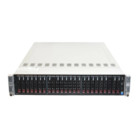
SUPERSERVER 2027TR-HTRF+/H70RF+/H71RF+/H72RF+ User's Manual Figure 6-1. Front and Rear Chassis Views Control Panel Control Panel Control Panel SATA/SAS Drives (24) Control Panel IPMI LAN Port Ethernet Ports USB Ports VGA Port Control Panel The control panel is located on the front of the chassis. The LEDs inform you of system status. -
Page 85: Chassis Cover
Chapter 6: Advanced Chassis Setup Chassis Cover Before operating the SC217 chassis for the fi rst time, it is important to remove the protective fi lm covering the top of the chassis, in order to allow for proper ventilation and cooling. Removing the Chassis Cover and Protective Film (Figure 6-2) 1. -
Page 86: Air Shrouds
SUPERSERVER 2027TR-HTRF+/H70RF+/H71RF+/H72RF+ User's Manual Air Shrouds Air shrouds concentrate airfl ow to maximize fan effi ciency. The SC217 chassis requires air shrouds for each serverboard node. Air shrouds vary depending upon the serverboard used. See the illustrations below. Installing an Air Shroud (Figure 6-3) 1. -
Page 87: Checking The Airfl Ow
Chapter 6: Advanced Chassis Setup Checking the Airfl ow Checking Airfl ow 1. Make sure there are no objects obstructing the airfl ow in and out of the chassis. In addition, if you are using a front bezel, make sure the bezel's fi lter is replaced periodically. - Page 88 SUPERSERVER 2027TR-HTRF+/H70RF+/H71RF+/H72RF+ User's Manual Changing a System Fan 1. If necessary, open the chassis while the power is running to determine which fan has failed. (Never run the server for an extended period of time with the chassis cover open.) 2.
- Page 89 Chapter 6: Advanced Chassis Setup Figure 6-5. Replacing a System Fan in the Fan Housing...
-
Page 90: Removing And Installing The Backplane
SUPERSERVER 2027TR-HTRF+/H70RF+/H71RF+/H72RF+ User's Manual Removing and Installing the Backplane The SC217 chassis backplane is located behind the hard drives and in front of the front system fans. Although backplane failure rarely occurs, in the event of a backplane failure, follow the instructions below. Removing the Backplane Removing the Backplane from the Chassis 1. - Page 91 Chapter 6: Advanced Chassis Setup 6. Loosen the three screws in the spring bar, located on the fl oor of the chassis, indicated by the arrows below (Figure 6-7). Figure 6-7. Loosening the Spring Bar Screws in the Floor of the Chassis 7.
-
Page 92: Installing The Backplane
SUPERSERVER 2027TR-HTRF+/H70RF+/H71RF+/H72RF+ User's Manual Installing the Backplane Installing the Backplane into the Chassis (Figure 6-9) 1. Ensure that all of the hard drive carriers have been removed from the bays in the front of the chassis and that the spring bar has been loosened as directed in the previous section. -
Page 93: Installing The Serverboard
Chapter 6: Advanced Chassis Setup Installing the Serverboard I/O Shield The I/O shield holds the serverboard ports in place. The I/O shield does not require installation (see Figure 6-10). Figure 6-10. I/O Shield Placement I/O Shields Permanent and Optional Standoffs Standoffs prevent short circuits by creating space between the serverboard and the chassis surface. - Page 94 SUPERSERVER 2027TR-HTRF+/H70RF+/H71RF+/H72RF+ User's Manual Figure 6-11. Removing Serverboard Node Drawer 4. Remove the expansion card brackets: 3a. Remove screw securing the expansion card bracket to the back of the node drawer. 3b. Lift the bracket out of the node drawer. 5.
- Page 95 Chapter 6: Advanced Chassis Setup Figure 6-12. Installing the Serverboard in the Serverboard Node Drawer 6-13...
-
Page 96: Adapter Card/Micro-Lp Card Replacement
SUPERSERVER 2027TR-HTRF+/H70RF+/H71RF+/H72RF+ User's Manual Adapter Card/Micro-LP Card Replacement Each serverboard drawer comes equipped with a adapter card which plugs into the backplane. In the unlikely event that the adapter card needs to be replaced, installation requires only a Phillips head screwdriver. Figure 6-13. -
Page 97: Micro-Lp Card/Micro-Lp Slot Setup
Chapter 6: Advanced Chassis Setup Micro-LP Card/Micro-LP Slot Setup The SC217 chassis includes expansion slots for Micro-LP cards. Each serverboard node supports one low profi le/half length Micro-LP card for a total of four per chassis, one per drawer. Note: the Micro-LP cards should already be installed in the motherboad drawers of the chassis and do not need replacement unless the serverboard needs replacing. -
Page 98: 6-10 Drive Bay Installation/Removal
SUPERSERVER 2027TR-HTRF+/H70RF+/H71RF+/H72RF+ User's Manual 6-10 Drive Bay Installation/Removal Accessing the Drive Bays SAS/SATA Drives: You do not need to access the inside of the chassis or remove power to replace or swap SAS/SATA drives. Proceed to the next step for instructions. You must use standard 1"... - Page 99 Chapter 6: Advanced Chassis Setup Removing Hard Drive Trays from the Chassis (Figure 6-15) 1. Press the release button on the drive tray. This extends the drive bay handle. 2. Use the handle to pull the drive out of the chassis. Figure 6-15.
- Page 100 SUPERSERVER 2027TR-HTRF+/H70RF+/H71RF+/H72RF+ User's Manual Installing a Drive into the Hard Drive Tray (Figure 6-16) The drives are mounted in drive carriers to simplify their installation and removal from the chassis. These carriers also help promote proper airfl ow for the drive bays. 1.
-
Page 101: 6-11 Power Supply
Chapter 6: Advanced Chassis Setup 6-11 Power Supply The SC217 chassis includes two 1620 Watt power supplies. This power supply is auto-switching capable. This enables it to automatically sense and operate at a 100v to 240v input voltage. An amber light will be illuminated on the power supply when the power is off. - Page 102 SUPERSERVER 2027TR-HTRF+/H70RF+/H71RF+/H72RF+ User's Manual Notes 6-20...
-
Page 103: Chapter 7 Bios
Chapter 7: BIOS Chapter 7 BIOS Introduction This chapter describes the AMI BIOS Setup Utility for the X9DRT-HF+ serverboard. The 16 Mb AMI BIOS® is stored in a Flash EEPROM and can be easily updated. This chapter describes the basic navigation of the AMI BIOS Setup Utility setup screens. -
Page 104: Starting The Setup Utility
SUPERSERVER 2027TR-HTRF+/H70RF+/H71RF+/H72RF+ User's Manual Starting the Setup Utility Normally, the only visible Power-On Self-Test (POST) routine is the memory test. As the memory is being tested, press the <Delete> key to enter the main menu of the AMI BIOS Setup Utility. From the main menu, you can access the other setup screens. -
Page 105: Advanced Settings Menu
Chapter 7: BIOS Supermicro X9DRT-HF+ Version This item displays the SMC version of the BIOS ROM used in this system. Build Date This item displays the date that the BIOS Setup utility was built. Memory Information Total Memory This displays the amount of memory that is available in the system. Advanced Settings Menu Boot Feature Quiet Boot... - Page 106 SUPERSERVER 2027TR-HTRF+/H70RF+/H71RF+/H72RF+ User's Manual AddOn ROM Display Mode This item sets the display mode for the Option ROM. Select Keep Current to use the current AddOn ROM Display setting. Select Force BIOS to use the Option ROM display mode set by the system BIOS. The options are Force BIOS and Keep Current.
- Page 107 Chapter 7: BIOS CPU Confi guration This submenu displays the information of the CPU as detected by the BIOS. It also allows the user to confi guration CPU settings. Socket 1 CPU Information/Socket 2 CPU Information This submenu displays the following information regarding the CPU installed in Socket 1 and (or) Socket 2 as detected by the BIOS.
- Page 108 SUPERSERVER 2027TR-HTRF+/H70RF+/H71RF+/H72RF+ User's Manual Active Processor Cores Set to Enabled to use a processor's second core and above. (Please refer to Intel's website for more information.) The options are All, 1, 2, 4, and 6. Limit CPUID Maximum Use this feature to set the maximum CPU ID value. Select Enabled to boot a legacy operating system that cannot support processors with extended CPUID functions.
- Page 109 Chapter 7: BIOS Intel® Virtualization Technology (Available when supported by the CPU) Select Enabled to support Intel Virtualization Technology, which will allow one platform to run multiple operating systems and applications in independent partitions, creating multiple "virtual" systems in one physical computer. The options are Enabled and Disabled.
- Page 110 SUPERSERVER 2027TR-HTRF+/H70RF+/H71RF+/H72RF+ User's Manual CPU C7 Report (Available when Power Technology is set to Custom) Select Enabled to allow the BIOS to report the CPU C7 State (ACPI C3) to the operating system. CPU C7 State is a processor-specifi c low C-State. The options are Enabled and Disabled.
- Page 111 Chapter 7: BIOS Chipset Confi guration North Bridge This feature allows the user to confi gure the following North Bridge settings. Integrated IO Confi guration Intel VT-d Select Enabled to enable Intel Virtualization Technology support for Direct I/O VT-d by reporting the I/O device assignments to the VMM (Virtual Working Memory) through the DMAR ACPI Tables.
- Page 112 SUPERSERVER 2027TR-HTRF+/H70RF+/H71RF+/H72RF+ User's Manual IIO 2 PCIe Port Bifurcation Control This submenu confi gures the following IO PCIe Port Bifurcation Control settings for IIO 2 PCIe ports to determine how the available PCI-Express lanes to be distributed between the PCI-Exp. Root Ports. QPI Confi...
- Page 113 Chapter 7: BIOS Sparing This item displays if memory sparing is supported by the serverboard. Memory sparing enhances system performance. DIMM Information The status of the memory modules detected by the BIOS is displayed. Memory Mode When Independent is selected, all DIMMs are available to the operating system.
- Page 114 SUPERSERVER 2027TR-HTRF+/H70RF+/H71RF+/H72RF+ User's Manual Patrol Scrub Patrol Scrubbing is a process that allows the CPU to correct correctable memory errors detected on a memory module and send the correction to the requestor (the original source). When this item is set to Enabled, the IO hub will read and write back one cache line every 16K cycles, if there is no delay caused by internal processing.
- Page 115 Chapter 7: BIOS South Bridge Confi guration This feature allows the user to confi gure the settings for the Intel PCH chip. PCH Information This feature displays the following PCH information. Name: This item displays the name of the PCH chip. Stepping: This item displays the status of the PCH stepping.
- Page 116 SUPERSERVER 2027TR-HTRF+/H70RF+/H71RF+/H72RF+ User's Manual SATA Confi guration When this submenu is selected, the AMI BIOS automatically detects the presence of IDE or SATA devices and displays the following items. SATA Port0~SATA Port5: The AMI BIOS displays the status of each SATA port as detected by the BIOS.
- Page 117 Chapter 7: BIOS RAID Mode The following items are displayed when RAID Mode is selected: Port 0~5 Hot Plug Select Enabled to enable hot-plug support for the particular port. The options are Enabled and Disabled. SCU Confi guration This menu is used to confi gure SCU (Storage Controller Unit) confi guration menu options.
- Page 118 SUPERSERVER 2027TR-HTRF+/H70RF+/H71RF+/H72RF+ User's Manual PERR# Generation Select Enabled to allow a PCI device to generate a PERR number for a PCI Bus Signal Error Event. The options are Enabled and Disabled. SERR# Generation Select Enabled to allow a PCI device to generate an SERR number for a PCI Bus Signal Error Event.
- Page 119 Chapter 7: BIOS Network Stack Select Enabled enable PXE (Preboot Execution Environment) or UEFI (Unifi ed Extensible Firmware Interface) for network stack support. The options are Enabled and Disabled. IPv4 PXE Support (Available when Network Stack is set to Enabled) Set this item to Enabled to activate IPv4 PXE Support.
- Page 120 SUPERSERVER 2027TR-HTRF+/H70RF+/H71RF+/H72RF+ User's Manual Device Mode Use this feature to select the desired mode for a serial port specifi ed. The options are Normal and High Speed. SOL Confi guration Serial Port Select Enabled to enable a serial port specifi ed by the user. The options are Enabled and Disabled.
- Page 121 Chapter 7: BIOS Console Redirection Select Enabled to use the SOL Port for Console Redirection. The options are Enabled and Disabled. Console Redirection Settings This feature allows the user to specify how the host computer will exchange data with the client computer, which is the remote computer used by the user. Terminal Type This feature allows the user to select the target terminal emulation type for Console Redirection.
- Page 122 SUPERSERVER 2027TR-HTRF+/H70RF+/H71RF+/H72RF+ User's Manual Flow Control This feature allows the user to set the fl ow control for Console Redirection to prevent data loss caused by buffer overfl ow. Send a "Stop" signal to stop sending data when the receiving buffer is full. Send a "Start" signal to start sending data when the receiving buffer is empty.
- Page 123 Chapter 7: BIOS Console Redirection Settings (for EMS) This feature allows the user to specify how the host computer will exchange data with the client computer, which is the remote computer used by the user. Out-of-Band Management Port The feature selects a serial port used by the Microsoft Windows Emergency Management Services (EMS) to communicate with a remote server.
- Page 124 SUPERSERVER 2027TR-HTRF+/H70RF+/H71RF+/H72RF+ User's Manual ACPI Settings Use this feature to confi gure Advanced Confi guration and Power Interface (ACPI) power management settings for your system. ACPI Sleep State Use this feature to select the ACPI State when the system is in sleep mode. Select S1 (CPU Stop Clock) to erase all CPU caches and stop executing instructions.
- Page 125 Chapter 7: BIOS Pending Operation Use this item to schedule an operation for the security device. The options are None, Enable Take Ownership, Disable Take Ownership, and TPM Clear. Note: During restart, the computer will reboot in order to execute the pending operation and change the state of the security device.
- Page 126 SUPERSERVER 2027TR-HTRF+/H70RF+/H71RF+/H72RF+ User's Manual TPM Support: Trusted Platform support TPM State: Trusted Platform state ME Subsystem This feature displays the following ME Subsystem Confi guration settings. • ME BIOS Interface Version • ME Version iSCSI Confi guration This item displays iSCSI confi guration information: iSCSI Initiator Name This item displays the name of the iSCSI Initiator, which is a unique name used in the world.
- Page 127 Chapter 7: BIOS Wake on LAN Select enabled to wake the system with a magic packet. The options are Enabled and Disabled. Blink LEDs This feature allows the user to specify the duration for LEDs to blink. The range is from 0 ~ 15 seconds.
-
Page 128: Event Logs
SUPERSERVER 2027TR-HTRF+/H70RF+/H71RF+/H72RF+ User's Manual Event Logs Select the Event Logs tab to access the following submenu items. Change SMBIOS Event Log Settings This feature allows the user to confi gure SMBIOS Event settings. Enabling/Disabling Options SMBIOS Event Log Select Enabled to enable SMBIOS (System Management BIOS) Event Logging during system boot. - Page 129 Chapter 7: BIOS Erasing Settings Erase Event Log Select Enabled to erase the SMBIOS (System Management BIOS) Event Log, which is completed before a event logging is initialized upon system reboot. The options are No, Yes, Next reset, and Yes, Every reset. When Log is Full Select Erase Immediately to immediately erase SMBIOS error event logs that exceed the limit when the SMBIOS event log is full.
-
Page 130: Ipmi
SUPERSERVER 2027TR-HTRF+/H70RF+/H71RF+/H72RF+ User's Manual IPMI Select the IPMI (Intelligent Platform Management Interface) tab to access the following submenu items. IPMI Firmware Revision, IPMI Status These items indicates your system IPMI fi rmware revision number and status. System Event Log SEL Components Select Enabled for all system event logging at bootup. - Page 131 Chapter 7: BIOS Custom EFI Logging Options Log EFI Status Codes Select Enabled to log EFI (Extensible Firmware Interface) Status Codes, Error Codes or Progress Codes. The options are Enabled and Disabled. Note: After making changes on a setting, be sure to reboot the system for the changes to take effect.
-
Page 132: Boot
SUPERSERVER 2027TR-HTRF+/H70RF+/H71RF+/H72RF+ User's Manual Boot This submenu allows the user to confi gure the following boot settings for the system. Boot Option Priorities Boot Option #1/ Boot Option #2/ Boot Option #3, etc. Use this feature to specify the sequence of boot device priority. Network Devices, USB Device BBS Priorities, Hard Disk Drives The above options appear when detected by the BIOS. -
Page 133: Security
Chapter 7: BIOS Security This menu allows the user to confi gure the following security settings for the system. Password Check Use this feature to determine when a password entry is required. Select Setup to require the password only when entering setup. Select Always to require the password when entering setup and on each boot. -
Page 134: Save & Exit
SUPERSERVER 2027TR-HTRF+/H70RF+/H71RF+/H72RF+ User's Manual Save & Exit This submenu allows the user to confi gure the Save and Exit settings for the system. Discard Changes and Exit Select this option to quit the BIOS Setup without making any permanent changes to the system confi... - Page 135 Chapter 7: BIOS Discard Changes Select this feature and press <Enter> to discard all the changes and return to the BIOS setup. When the dialog box appears, asking you if you want to load previous values, select Yes to load the values previous saved, or select No to keep the changes you've made so far.
- Page 136 SUPERSERVER 2027TR-HTRF+/H70RF+/H71RF+/H72RF+ User's Manual Notes 7-34...
-
Page 137: Appendix A Bios Error Beep Codes
Appendix A: BIOS Error Beep Codes Appendix A BIOS Error Beep Codes During the POST (Power-On Self-Test) routines, which are performed each time the system is powered on, errors may occur. Non-fatal errors are those which, in most cases, allow the system to continue the boot-up process. - Page 138 SUPERSERVER 2027TR-HTRF+/H70RF+/H71RF+/H72RF+ User's Manual Notes...
-
Page 139: Appendix B System Specifi Cations
Appendix B: System Specifi cations Appendix B System Specifi cations Note: Unless noted specifi cations apply to a complete system (all serverboards). Processors Two E5-2600 series processors per node in Socket R LGA 2011 type sockets Note: please refer to our website for details on supported processors. Chipset One C602 chipset per node BIOS... - Page 140 SUPERSERVER 2027TR-HTRF+/H70RF+/H71RF+/H72RF+ User's Manual Chassis SC217HQ-R1K62MB (2U rackmount) Dimensions: (WxHxD) 17.25 x 3.47 x 26.75 in. (438 x 88 x 679 mm) Weight Gross (Bare Bone): 85 lbs. (38.6 kg.) System Cooling The system has four (4) 8-cm PWM system cooling fans System Input Requirements AC Input Voltage: 85-264V AC auto-range Rated Input Current: 15 - 5A...
- Page 141 Appendix B: System Specifi cations Notes...
- Page 142 SUPERSERVER 2027TR-HTRF+/H70RF+/H71RF+/H72RF+ User's Manual (continued from front) The products sold by Supermicro are not intended for and will not be used in life support systems, medical equipment, nuclear facilities or systems, aircraft, aircraft devices, aircraft/emergency communication devices or other critical systems whose failure to perform be reasonably expected to result in signifi...
Need help?
Do you have a question about the SUPERSERVER 2027TR-HTRF+ and is the answer not in the manual?
Questions and answers