Table of Contents
Advertisement
Quick Links
Advertisement
Table of Contents

Related Manuals for Supero A+ 2022TC-HTRF4


Summary of Contents for Supero A+ 2022TC-HTRF4
- Page 1 UPER ® A+ SERVER 2022TC-HTRF4 USER'S MANUAL Revision 1.0c...
- Page 2 The information in this User’s Manual has been carefully reviewed and is believed to be accurate. The vendor assumes no responsibility for any inaccuracies that may be contained in this document, makes no commitment to update or to keep current the information in this manual, or to notify any person or organization of the updates.
- Page 3 Preface Preface About This Manual This manual is written for professional system integrators and PC technicians. It provides information for the installation and use of the A+ Server 2022TC-HTRF4. Installation and maintainance should be performed by experienced technicians only. The A+ Server 2022TC-HTRF4 is a high-end server based on the SC827H-R1620BP 2U rackmount chassis and the dual processor H8DCT-HLN4F serverboard.
- Page 4 A+ Server 2022TC-HTRF4 USER'S MANUAL Chapter 6: Advanced Chassis Setup Refer to Chapter 6 for detailed information on the SC827H-R1620BP server chassis. You should follow the procedures given in this chapter when installing, removing or reconfiguring SATA or peripheral drives and when replacing system power supply units and cooling fans.
-
Page 5: Table Of Contents
Preface Contents Chapter 1 Introduction Overview ......................1-1 Serverboard Features ..................1-2 Processor ......................1-2 Memory ......................1-2 Onboard SATA ....................1-2 PCI Expansion Slots ..................1-2 Onboard Controllers/Ports ................1-2 Other Features ....................1-4 Server Chassis Features ................1-4 System Power .................... - Page 6 A+ Server 2022TC-HTRF4 USER'S MANUAL Installing the System into a Rack ..............2-4 Separating the Sections of the Rack Rails ............. 2-4 Installing the Inner Rail Extension ..............2-5 Outer Rack Rails ..................... 2-6 Checking the Serverboard Setup ..............2-8 Checking the Drive Bay Setup ................
- Page 7 Preface Installing Memory .................... 5-8 Memory Support ....................5-8 Maximum Memory ................... 5-8 DIMM Module Population Configuration ..........5-10 Adding PCI Expansion Cards ................5-11 Motherboard Details ..................5-11 Connector Definitions ..................5-14 Jumper Settings .................... 5-17 Explanation of Jumpers ................5-17 5-10 Onboard Indicators ..................
- Page 8 A+ Server 2022TC-HTRF4 USER'S MANUAL Chapter 7 BIOS Introduction ...................... 7-1 Main Menu ...................... 7-2 Advanced Settings Menu ................7-2 Security Menu ....................7-15 Boot Menu ..................... 7-16 Exit Menu ...................... 7-17 Appendix A BIOS Error Beep Codes Appendix B System Specifications viii...
-
Page 9: Chapter 1 Introduction
Chapter 1: Introduction Chapter 1 Introduction Overview The A+ Server 2022TC-HTRF4 is a high-end server comprised of four main subsystems: the SC827H-R1620BP 2U server chassis and the H8DCT-HLN4F dual processor serverboard. Please refer to our web site for information on operating systems that have been certified for use with the system (www.supermicro.com). -
Page 10: Serverboard Features
A+ SERVER 2022TC-HTRF4 USER'S MANUAL Serverboard Features At the heart of the A+ Server 2022TC-HTRF4 lies four H8DCT-HLN4F dual processor motherboards based upon one AMD SR5670 chipset and one SP5100 Southbridge chipset. Below are the main features of the H8DCT-HLN4F. Note that the features on each board are quadrupled for the server, which includes four nodes. - Page 11 Chapter 1: Introduction Figure 1-1. AMD SR5670 and SP5100 Chipset: System Block Diagram Note: This is a general block diagram and may not exactly represent the features on your motherboard. See the previous pages for the actual specifications of your motherboard.
-
Page 12: Other Features
A+ SERVER 2022TC-HTRF4 USER'S MANUAL Other Features Other onboard features that promote system health include voltage monitors, a auto-switching voltage regulators, chassis and CPU overheat sensors and virus protection. Server Chassis Features The following is a general outline of the main features of the SC827H-R1620BP server chassis. -
Page 13: Rear I/O
Chapter 1: Introduction Rear I/O The 2022TC-HTRF4 provides a low-profile expansion card slot, one IPMI Ethernet port and four gigabit Ethernet ports, and one KVM port (VGA+COM+2xUSB via dongle) per node. Cooling System The SC827 chassis accepts four system fans powered from the backpane. When node A or node B are powered on, both fans on the left of the chassis will run. -
Page 14: Contacting Supermicro
A+ SERVER 2022TC-HTRF4 USER'S MANUAL Contacting Supermicro Headquarters Address: Super Micro Computer, Inc. 980 Rock Ave. San Jose, CA 95131 U.S.A. Tel: +1 (408) 503-8000 Fax: +1 (408) 503-8008 Email: marketing@supermicro.com (General Information) support@supermicro.com (Technical Support) Web Site: www.supermicro.com Europe Address: Super Micro Computer B.V. -
Page 15: Twin 2 : System Notes
Chapter 1: Introduction 2U Twin : System Notes As a 2U Twin configuration, the 2022TC-HTRF4 is a unique server system. With four system boards incorporated into a single chassis acting as four separate nodes, there are several points you should keep in mind. Nodes Each of the four serverboards act as a separate node in the system. - Page 16 A+ SERVER 2022TC-HTRF4 USER'S MANUAL Notes...
-
Page 17: Chapter 2 Server Installation
Chapter 2: Server Installation Chapter 2 Server Installation Overview This chapter provides a quick setup checklist to get your A+ Server 2022TC-HTRF4 up and running. Following these steps in the order given should enable you to have the system operational within a minimum amount of time. This quick setup assumes that your system has come to you with the processors and memory preinstalled. -
Page 18: Warnings And Precautions
A+ SERVER 2022TC-HTRF4 USER'S MANUAL • This product is for installation only in a Restricted Access Location (dedicated equipment rooms, service closets and the like). • This product is not suitable for use with visual display work place devices acccording to §2 of the the German Ordinance for Work with Visual Display Units. Warnings and Precautions Rack Precautions •... -
Page 19: Rack Mounting Considerations
Chapter 2: Server Installation Rack Mounting Considerations Ambient Operating Temperature If installed in a closed or multi-unit rack assembly, the ambient operating temperature of the rack environment may be greater than the ambient temperature of the room. Therefore, consideration should be given to installing the equipment in an environment compatible with the manufacturer’s maximum rated ambient temperature (Tmra). -
Page 20: Installing The System Into A Rack
A+ SERVER 2022TC-HTRF4 USER'S MANUAL Installing the System into a Rack This section provides information on installing the SC827 chassis into a rack unit with the quick-release rails provided. There are a variety of rack units on the market, which may mean the assembly procedure will differ slightly. You should also refer to the installation instructions that came with the rack unit you are using. -
Page 21: Installing The Inner Rail Extension
Chapter 2: Server Installation Installing the Inner Rail Extension The SC827 chassis includes a set of inner rails in two sections: inner rails and inner rail extensions. The inner rails are pre-attached to the chassis, and do not interfere with normal use of the chassis if you decide not to use a server rack. The inner rail extension is attached to the inner rail to mount the chassis in the rack. -
Page 22: Outer Rack Rails
A+ SERVER 2022TC-HTRF4 USER'S MANUAL Outer Rack Rails Outer rails attach to the rack and hold the chassis in place. The outer rails for the SC827 chassis extend between 30 inches and 33 inches. Installing the Outer Rails to the Rack (Figure 2-3) 1. - Page 23 Chapter 2: Server Installation Installing the Chassis into a Rack (Figure 2-4) 1. Extend the outer rails as illustrated above. 2. Align the inner rails of the chassis with the outer rails on the rack. 3. Slide the inner rails into the outer rails, keeping the pressure even on both sides.
-
Page 24: Checking The Serverboard Setup
A+ SERVER 2022TC-HTRF4 USER'S MANUAL Checking the Serverboard Setup After you install the 2022TC-HTRF4 in the rack, you will need to open the unit to make sure the serverboard is properly installed and all the connections have been made. Accessing the inside of the System Before operating the server for the first time, it is important to remove the protective film covering the top of the chassis, in order to allow for proper ventilation and cooling. -
Page 25: Checking The Drive Bay Setup
Chapter 2: Server Installation Checking the Components and Setup 1. You may have one or two processors already installed into the serverboard. Each processor needs its own heat sink. See Chapter 5 for instructions on processor and heat sink installation. 2. - Page 26 A+ SERVER 2022TC-HTRF4 USER'S MANUAL Notes 2-10...
-
Page 27: Chapter 3 System Interface
Chapter 3: System Interface Chapter 3 System Interface Overview Several buttons and LEDs indicate the status of the system. There are four control panels, two on each side of the front edges of the chassis, that each monitor the associated computing node. There are also LEDs on the drive carriers that indicate the status of the drive. -
Page 28: Control Panel Buttons
A+ SERVER 2022TC-HTRF4 USER'S MANUAL Control Panel Buttons There are two push-buttons on each control panel on the front of the chassis. They controll the computing node associated with that control panel. Power: The main power switch applies or removes power to the node from the power supply. -
Page 29: Drive Carrier Leds
Chapter 3: System Interface Information LED: Alerts operator of several states, as noted in the table below. Informational LED Status Description An overheat condition has occured. Continuously on and red (This may be caused by cable congestion.) Blinking red (1Hz) Fan failure, check for an inoperative fan. - Page 30 A+ SERVER 2022TC-HTRF4 USER'S MANUAL Notes...
-
Page 31: Chapter 4Standardized Warning Statements For Ac Systems
Chapter 4: Warning Statements for AC Systems Chapter 4 Standardized Warning Statements for AC Systems About Standardized Warning Statements The following statements are industry standard warnings, provided to warn the user of situations which have the potential for bodily injury. Should you have questions or experience difficulty, contact Supermicro's Technical Support department for assistance. - Page 32 A+ SERVER 2022TC-HTRF4 User's Manual Warnung WICHTIGE SICHERHEITSHINWEISE Dieses Warnsymbol bedeutet Gefahr. Sie befinden sich in einer Situation, die zu Verletzungen führen kann. Machen Sie sich vor der Arbeit mit Geräten mit den Gefahren elektrischer Schaltungen und den üblichen Verfahren zur Vorbeugung vor Unfällen vertraut.
- Page 33 Warning Statements for AC Systems جسذٌة اصابة ًتتسبب ف حالة ٌوكي أى ًاًك ف خطز ًٌٌع هذا الزهز !تحذٌز الذوائز بالوخاطز الٌاجوة عي ي على علن ، ك هعذات تعول على أي قبل أى الكهزبائٍة حىادث أي وقىع وٌع ل الىقائٍة...
-
Page 34: Installation Instructions
A+ SERVER 2022TC-HTRF4 User's Manual Installation Instructions Warning! Read the installation instructions before connecting the system to the power source. 設置手順書 システムを電源に接続する前に、 設置手順書をお読み下さい。 警告 将此系统连接电源前,请先阅读安装说明。 警告 將系統與電源連接前,請先閱讀安裝說明。 Warnung Vor dem Anschließen des Systems an die Stromquelle die Installationsanweisungen lesen. ¡Advertencia! Lea las instrucciones de instalación antes de conectar el sistema a la red de alimentación. -
Page 35: Circuit Breaker
Chapter 4: Warning Statements for AC Systems Circuit Breaker Warning! This product relies on the building's installation for short-circuit (overcurrent) protection. Ensure that the protective device is rated not greater than: 250 V, 20 A. サーキッ ト ・ ブレーカー この製品は、 短絡 (過電流) 保護装置がある建物での設置を前提としています。 保護装置の定格が250 V、... -
Page 36: Power Disconnection Warning
A+ SERVER 2022TC-HTRF4 User's Manual 경고! 이 제품은 전원의 단락(과전류)방지에 대해서 전적으로 건물의 관련 설비에 의존합니다. 보호장치의 정격이 반드시 250V(볼트), 20A(암페어)를 초과하지 않도록 해야 합니다. Waarschuwing Dit product is afhankelijk van de kortsluitbeveiliging (overspanning) van uw electrische installatie. Controleer of het beveiligde aparaat niet groter gedimensioneerd is dan 220V, 20A. - Page 37 Chapter 4: Warning Statements for AC Systems ¡Advertencia! El sistema debe ser disconnected de todas las fuentes de energía y del cable eléctrico quitado de los módulos de fuente de alimentación antes de tener acceso el interior del chasis para instalar o para quitar componentes de sistema. Attention Le système doit être débranché...
-
Page 38: Equipment Installation
A+ SERVER 2022TC-HTRF4 User's Manual Equipment Installation Warning! Only trained and qualified personnel should be allowed to install, replace, or service this equipment. 機器の設置 トレーニングを受け認定された人だけがこの装置の設置、 交換、 またはサービスを許可 されています。 警告 只有经过培训且具有资格的人员才能进行此设备的安装、更换和维修。 警告 只有經過受訓且具資格人員才可安裝、更換與維修此設備。 Warnung Das Installieren, Ersetzen oder Bedienen dieser Ausrüstung sollte nur geschultem, qualifiziertem Personal gestattet werden. -
Page 39: Restricted Area
Chapter 4: Warning Statements for AC Systems Waarschuwing Deze apparatuur mag alleen worden geïnstalleerd, vervangen of hersteld door geschoold en gekwalificeerd personeel. Restricted Area Warning! This unit is intended for installation in restricted access areas. A restricted access area can be accessed only through the use of a special tool, lock and key, or other means of security. -
Page 40: Battery Handling
A+ SERVER 2022TC-HTRF4 User's Manual אזור עם גישה מוגבלת !אזהרה יש להתקין את היחידה באזורים שיש בהם הגבלת גישה. הגישה ניתנת בעזרת .)'כלי אבטחה בלבד (מפתח, מנעול וכד محظورة مناطق ٍنتركُبها ف هذه انىحذة تخصيص تم ،أداة خاصت من خالل استخذاو فقط... - Page 41 Chapter 4: Warning Statements for AC Systems Warnung Bei Einsetzen einer falschen Batterie besteht Explosionsgefahr. Ersetzen Sie die Batterie nur durch den gleichen oder vom Hersteller empfohlenen Batterietyp. Entsorgen Sie die benutzten Batterien nach den Anweisungen des Herstellers. Attention Danger d'explosion si la pile n'est pas remplacée correctement. Ne la remplacer que par une pile de type semblable ou équivalent, recommandée par le fabricant.
-
Page 42: Redundant Power Supplies
A+ SERVER 2022TC-HTRF4 User's Manual Redundant Power Supplies Warning! This unit might have more than one power supply connection. All connections must be removed to de-energize the unit. 冗長電源装置 このユニッ トは複数の電源装置が接続されている場合があります。 ユニッ トの電源を切るためには、 すべての接続を取り外さなければなりません。 警告 此部件连接的电源可能不止一个,必须将所有电源断开才能停止给该部件供电。 警告 此裝置連接的電源可能不只一個,必須切斷所有電源才能停止對該裝置的供電。 Warnung Dieses Gerät kann mehr als eine Stromzufuhr haben. Um sicherzustellen, dass der Einheit kein trom zugeführt wird, müssen alle Verbindungen entfernt werden. -
Page 43: Backplane Voltage
Chapter 4: Warning Statements for AC Systems امداد الطاقة بوحدات عدة اتصاالت جهاز ال يكون لهذا قد الكهرباء عن وحدة ال لعسل كافة االتصاالت يجب إزالة 경고! 이 장치에는 한 개 이상의 전원 공급 단자가 연결되어 있을 수 있습니다. 이 장치에 전원을... -
Page 44: Comply With Local And National Electrical Codes
A+ SERVER 2022TC-HTRF4 User's Manual מתח בפנל האחורי !הרה אז קיימת סכנת מתח בפנל האחורי בזמן תפעול המערכת. יש להיזהר במהלך .העבודה اللىحة أوالطاقة المىجىدة على التيار الكهزبائي مه خطز هناك هذا الجهاس خدمة كه حذرا عند يعمل النظام عندما يكىن 경고! 시스템이... -
Page 45: Product Disposal
Chapter 4: Warning Statements for AC Systems Attention L'équipement doit être installé conformément aux normes électriques nationales et locales. תיאום חוקי החשמל הארצי !אזהרה הציוד חייבת להיות תואמת לחוקי החשמל המקומיים והארציים התקנת المتعلقة المحلية والىطىية قىاويه يجب أن يمتثل لل الكهربائية... -
Page 46: Hot Swap Fan Warning
A+ SERVER 2022TC-HTRF4 User's Manual ¡Advertencia! Al deshacerse por completo de este producto debe seguir todas las leyes y reglamentos nacionales. Attention La mise au rebut ou le recyclage de ce produit sont généralement soumis à des lois et/ou directives de respect de l'environnement. Renseignez-vous auprès de l'organisme compétent. - Page 47 Chapter 4: Warning Statements for AC Systems 警告 當您從機架移除風扇裝置,風扇可能仍在轉動。小心不要將手指、螺絲起子和其他 物品太靠近風扇。 Warnung Die Lüfter drehen sich u. U. noch, wenn die Lüfterbaugruppe aus dem Chassis genommen wird. Halten Sie Finger, Schraubendreher und andere Gegenstände von den Öffnungen des Lüftergehäuses entfernt. ¡Advertencia! Los ventiladores podran dar vuelta cuando usted quite ell montaje del ventilador del chasis.
-
Page 48: Power Cable And Ac Adapter
A+ SERVER 2022TC-HTRF4 User's Manual Power Cable and AC Adapter Warning! When installing the product, use the provided or designated connection cables, power cables and AC adaptors. Using any other cables and adaptors could cause a malfunction or a fire. Electrical Appliance and Material Safety Law prohibits the use of UL or CSA -certified cables (that have UL/CSA shown on the code) for any other electrical devices than products designated by Supermicro only. - Page 49 Chapter 4: Warning Statements for AC Systems Attention Lors de l'installation du produit, utilisez les bables de connection fournis ou désigné. L'utilisation d'autres cables et adaptateurs peut provoquer un dysfonctionnement ou un incendie. Appareils électroménagers et de loi sur la sécurité Matériel interdit l'utilisation de UL ou CSA câbles certifiés qui ont UL ou CSA indiqué...
- Page 50 A+ SERVER 2022TC-HTRF4 User's Manual Notes 4-20...
-
Page 51: Chapter 5 Advanced Motherboard Setup
Chapter 5: Advanced Motherboard Setup Chapter 5 Advanced Motherboard Setup This chapter covers the steps required to install the H8DCT-HLN4F motherboard into the chassis, connect the data and power cables and install add-on cards. All motherboard jumpers and connections are also described. A layout and quick reference chart are included in this chapter for your reference. -
Page 52: Motherboard Installation
A+ SERVER 2022TC-HTRF4 USER'S MANUAL Motherboard Installation This section explains the first step of physically mounting the H8DCT-HLN4F into the SC827 chassis. The 2022TC-HTRF4 is a highly complicated system. It is rec- ommended that motherboard removal/installation be done by a Supermicro trained technician. -
Page 53: Rear I/O Ports
Chapter 5: Advanced Motherboard Setup Rear I/O Ports The rear I/O ports are color coded. See Figure 5-1 below for the colors and locations of the various I/O ports. Figure 5-1. Rear I/O Ports Rear I/O Ports 1. LAN3 3. LAN4 5. -
Page 54: Processor And Heatsink Installation
A+ SERVER 2022TC-HTRF4 USER'S MANUAL Processor and Heatsink Installation Caution: Exercise extreme caution when handling and installing the processor. Supermicro recommends that you utilize a processor installation/removal tool to install or remove the processor from the serverboard without causing the processor or serverboard damage. - Page 55 Chapter 5: Advanced Motherboard Setup 3. Align pin 1 of the CPU with pin 1 of the socket. Once aligned, carefully place the CPU into the socket. Do not drop the CPU on the socket, move the CPU horizontally or vertically or rub the CPU against the socket or against any pins of the socket, which may damage the CPU and/or the socket.
-
Page 56: Installing A Cpu Heatsink
A+ SERVER 2022TC-HTRF4 USER'S MANUAL Installing a CPU Heatsink 1. Remove power from the system and unplug the AC power cord from the power supply. 2. Do not apply any thermal grease to the heatsink or the CPU die; Screw #1 Screw #2 the required amount has already been applied. -
Page 57: Removing The Heatsink
Chapter 5: Advanced Motherboard Setup Removing the Heatsink Caution! We do not recommend that the CPU or the heatsink be removed. However, if you do need to uninstall the heatsink, please follow the instructions below to prevent damage to the CPU or the CPU socket. 1. -
Page 58: Installing Memory
A+ SERVER 2022TC-HTRF4 USER'S MANUAL Installing Memory Note: In single and dual-CPU configurations, memory must be installed in the DIMM slots associated with the installed CPU(s). Installing Memory 1. Insert each memory module vertically into its slot, paying attention to the notch along the bottom of the module to prevent inserting the module incorrectly (see Figure 5-2). - Page 59 Chapter 5: Advanced Motherboard Setup Figure 5-2. Installing DIMM into Slot To Install: Insert Notch Notch module vertically and press down until it snaps into place. Front View Pay attention to the alignment notch at the bottom. Note: Notch should align with To Remove: Use the receptive key point on the slot.
-
Page 60: Dimm Module Population Configuration
A+ SERVER 2022TC-HTRF4 USER'S MANUAL DIMM Module Population Configuration For memory to work properly, follow the tables below for memory installation: Per Channel DIMM Populations Options Max. MHz, 1.5V Max. MHz, Max. GB/ DIMM Type DIMM A DIMM B DIMM C DIMMs 1.35V DIMMs Channel... -
Page 61: Adding Pci Expansion Cards
Chapter 5: Advanced Motherboard Setup Adding PCI Expansion Cards The 2022TC-HTRF4 includes one preinstalled riser card designed specifically for use in the SC827H-R1620BP 2U rackmount chassis. These riser cards support one low-profile PCI Express x16 card up to 6.59” in length per node. Installing an Expansion Card 1. - Page 62 A+ SERVER 2022TC-HTRF4 USER'S MANUAL Connector Description GPU FAN 1 GPU Fan Header JIPMB1 System Management Bus Header (SMBus) IPMI LAN Dedicated IPMI LAN Port InfiniBand Connector JOH1 Overheat Warning Header JTPM1 Trusted Platform Module Header SMC Proprietary Slot for Power, FP Control & SATA connectors Keyboard/Video/Mouse Port LAN1/2/3/4 Gigabit Ethernet (RJ45) Ports...
- Page 63 Chapter 5: Advanced Motherboard Setup Figure 5-3. H8DCT-HLN4F Motherboard Layout (not drawn to scale) JIB1 InfiniBand SPEAKER SR5670 SR5690 SP5100 CPU1 CPU2 Note: Jumpers not indicated are for test purposes only. 5-13...
-
Page 64: Connector Definitions
A+ SERVER 2022TC-HTRF4 USER'S MANUAL Connector Definitions Fan Header Fan Header Pin Definitions This motherboard has one GPU fan header Pin# Definition (GPU_Fan1). This 4-pin fan header is Ground backward compatible with 3-pin fans. +12V However, fan speed control is available for Tachometer 4-pin fans only. - Page 65 Chapter 5: Advanced Motherboard Setup IPMB JIPMB1 Pin Definitions A System Management Bus header for the Pin# Definition IPMI slot is located at JIPMB1. Connect the Data appropriate cable here to use the IPMB I2C Ground connection on your system. Clock No Connection Overheat LED...
- Page 66 A+ SERVER 2022TC-HTRF4 USER'S MANUAL Trusted Platform Module Header Trusted Platform Module Header Pin Definitions (JTPM1) The JTPM1 header is used to connect a Pin# Definition Pin# Definition Trusted Platform Module (TPM), available LCLK separately from a third-party vendor. A TPM LFRAME No Pin is a security device that allows encryption...
-
Page 67: Jumper Settings
Chapter 5: Advanced Motherboard Setup Jumper Settings Connector Pins Explanation of Jumpers To modify the operation of the motherboard, Jumper jumpers can be used to choose between optional settings. Jumpers create shorts between two pins to change the function Setting of the connector. - Page 68 A+ SERVER 2022TC-HTRF4 USER'S MANUAL I2C to PCI-Express Slots C to PCI-Express Slot Jumper Settings C1/JI C2 slots allows you to enable the I C1/JI bus to communicate with a PCI-Express slot. Jumper Setting Definition For the jumpers to work properly, please set Closed Enabled both jumpers to the same setting.
-
Page 69: 5-10 Onboard Indicators
Chapter 5: Advanced Motherboard Setup InfiniBand Port Enable/Disable InfiniBand Port Jumper Enable (JIB1) JIB1 enables or disables the InfiniBand port Jumper Settings on H8DCT-HLN4F serverboard. The default Jumper Setting Definition position is on pins 1 and 2 to enable the port. Pins 1-2 Enabled See the table below for jumper settings. - Page 70 A+ SERVER 2022TC-HTRF4 USER'S MANUAL InfiniBand LED Indicators InfiniBand LED (LE2) Activity LED Two InfiniBand LED indicators (LE2/LE3) Color Status Definition are located near the InfiniBand port of the Green Solid InfiniBand Connected H8DCT-HLN4F serverboard. The green No Connection LED (LE2) is the InfiniBand link LED while the yellow LED (LE3) indicates activity.
-
Page 71: 5-11 Enabling Sata Raid
Chapter 5: Advanced Motherboard Setup 5-11 Enabling SATA RAID Now that the hardware is set up, you must install the operating system and the SATA RAID drivers, if you wish to use RAID with your SATA drives. The installation procedure differs depending on whether you wish to have the operating system installed on a RAID array or on a separate non-RAID drive. -
Page 72: Enabling Sata Raid In The Bios
A+ SERVER 2022TC-HTRF4 USER'S MANUAL Enabling SATA RAID in the BIOS Before installing the Windows operating system, you must change some settings in the BIOS. Boot up the system and hit the <Delete> key to enter the BIOS Setup Utlility. After the setup utility loads, 1. -
Page 73: Using The Dothill And Adaptec Raid Utility
Chapter 5: Advanced Motherboard Setup Figure 5-5. DotHill RAID Utility Program Screen Figure 5-6. Adaptec RAID Utility Program Screen Using the DotHill and Adaptec RAID Utility The RAID Utility program allows you to define the drives you want to include in the RAID array and the mode and type of RAID. -
Page 74: Installing The Raid Driver During Os Installation
A+ SERVER 2022TC-HTRF4 USER'S MANUAL Installing the RAID Driver During OS Installation You may also use the procedure below to install the RAID driver during the Windows OS installation: 1. With the Windows OS installation CD-ROM in the CD drive, restart the system. - Page 75 Chapter 5: Advanced Motherboard Setup Figure 5-7. Driver/Tool Installation Display Screen Note: Click the icons showing a hand writing on paper to view the readme files for each item. Click the computer icons to the right of these items to install each item (from top to the bottom) one at a time.
-
Page 76: Superdoctor Iii
A+ SERVER 2022TC-HTRF4 USER'S MANUAL must be made within SuperDoctor III, as the SuperDoctor III settings override the BIOS settings. To set the BIOS temperature threshold settings again, you would first need to uninstall SuperDoctor III. Figure 5-8. SuperDoctor III Interface Display Screen (Health Information) Figure 5-9. -
Page 77: 5-13 Serverboard Battery
Chapter 5: Advanced Motherboard Setup 5-13 Serverboard Battery Caution: There is a danger of explosion if the onboard battery is installed upside down, which will reverse its polarites (see Figure 5-9). This battery must be replaced only with the same or an equivalent type recommended by the manufacturer (CR2032). - Page 78 A+ SERVER 2022TC-HTRF4 USER'S MANUAL Notes 5-28...
-
Page 79: Chapter 6 Advanced Chassis Setup
Chapter 6: Advanced Chassis Setup Chapter 6 Advanced Chassis Setup This chapter covers the steps required to install components and perform maintenance on the SC827H-R1620BP chassis. For component installation, follow the steps in the order given to eliminate the most common problems encountered. If some steps are unnecessary, skip ahead to the step that follows. -
Page 80: Control Panel
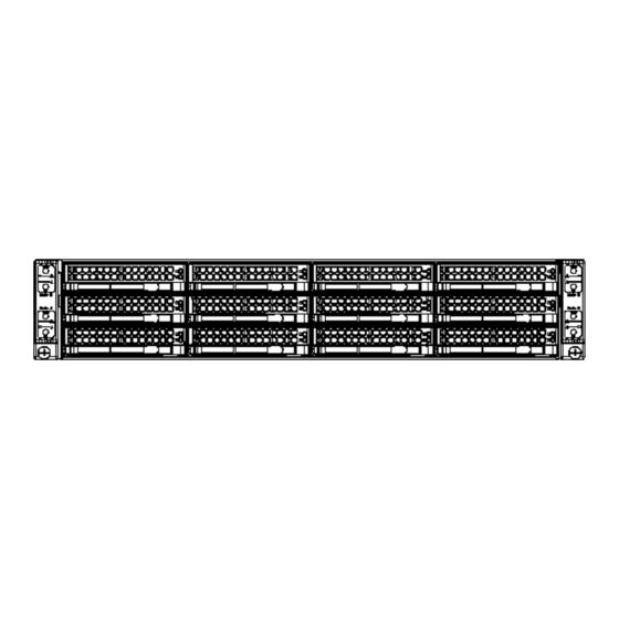
A+ SERVER 2022TC-HTRF4 USER'S MANUAL Unpacking The serverboard is shipped in antistatic packaging to avoid static damage. When unpacking the board, make sure the person handling it is static protected. Figure 6-1. Front and Rear Chassis Views Control Panel Control Panel Control Panel SATA Drives (12) Control Panel... -
Page 81: Chassis Cover
Chapter 6: Advanced Chassis Setup Chassis Cover Before operating the server for the first time, it is important to remove the protective film covering the top of the chassis to allow for proper ventilation and cooling. Removing the Chassis Cover and Protective Film (Figure 6-2) 1. -
Page 82: Air Shrouds
A+ SERVER 2022TC-HTRF4 USER'S MANUAL Air Shrouds Air shrouds concentrate airflow to maximize fan efficiency. The SC827 chassis requires air shrouds for each motherboard node. Air shrouds vary depending upon the motherboard used. See the illustrations below. Installing an Air Shroud (Figure 6-3) 1. -
Page 83: Checking The Airflow
Chapter 6: Advanced Chassis Setup Checking the Airflow Checking Airflow • Make sure there are no objects to obstruct airflow in and out of the server. In addition, if you are using a front bezel, make sure the bezel filter is replaced periodically. -
Page 84: System Fans
A+ SERVER 2022TC-HTRF4 USER'S MANUAL System Fans Four fans circulate air through the chassis to lower the internal temperature. They are not hot-swappable. No tools are required for installation. Changing a System Fan 1. If necessary, open the chassis while the power is running to determine which fan has failed. - Page 85 Chapter 6: Advanced Chassis Setup 6. Replace the fan housing into the chassis and reconnect the fan's power cord to the backplane (Figure 6-5). 7. Confirm that the fan is working properly before replacing the chassis cover. Figure 6-5. System Fan Placement...
-
Page 86: Removing And Installing The Backplane
A+ SERVER 2022TC-HTRF4 USER'S MANUAL Removing and Installing the Backplane The SC827 chassis backplane is located behind the hard drives and in front of the front system fans. In order to change jumper settings on the backplane, it may be necessary to remove the backplane from the chassis. - Page 87 Chapter 6: Advanced Chassis Setup 6. Loosen the three screws in the spring bar, located on the floor of the chassis, indicated by the arrows below (Figure 6-7). Figure 6-7. Loosening the Spring Bar Screws in the Floor of the Chassis 7.
-
Page 88: Installing The Backplane
A+ SERVER 2022TC-HTRF4 USER'S MANUAL Installing the Backplane Installing the Backplane into the Chassis (Figure 6-9) 1. Ensure that all of the hard drive trays have been removed from the bays in the front of the chassis and that the spring bar has been loosened as directed in the previous section. -
Page 89: Adapter Card Replacement
Chapter 6: Advanced Chassis Setup Adapter Card Replacement Each motherboard drawer comes equipped with an adapter card which plugs into the backplane. In the unlikely event that the adapter card needs to be replaced, installation requires only a Phillips head screwdriver. Removing the Adapter Card 1. -
Page 90: Add-On Card/Expansion Slot Setup
A+ SERVER 2022TC-HTRF4 USER'S MANUAL Add-on Card/Expansion Slot Setup The SC827 chassis includes I/O slots for add-on cards and expansion cards. Each side supports one low profile/half length add-on card for a total of four per chassis, one per drawer. Note: The motherboard node drawer accepts expansion cards up to a maximum of 6.59"... - Page 91 Chapter 6: Advanced Chassis Setup Figure 6-14. Installing the Low Profile Add-On Card Add-on Card Riser Card PCI Slot Screw Shield Add-on Card Riser Card Bracket Add-on Card Bracket Screws Note: The motherboard node drawer is an example only, actual layout differs slightly 4.
-
Page 92: Drive Bay Installation/Removal
A+ SERVER 2022TC-HTRF4 USER'S MANUAL Drive Bay Installation/Removal For SATA drives, you do not need to access the inside of the chassis or remove power to replace or swap drives. Use standard 1" high, SATA drives in the system. Note: Enterprise level hard disk drives are recommended for use in Supermicro chassis and servers. - Page 93 Chapter 6: Advanced Chassis Setup Removing Hard Drive Trays from the Chassis 1. Press the release button on the drive tray. This extends the drive bay handle. 2. Use the handle to pull the drive out of the chassis (Figure 6-14). Figure 6-14.
- Page 94 A+ SERVER 2022TC-HTRF4 USER'S MANUAL The drives are mounted in drive carriers to simplify their installation and removal from the chassis (Figure 6-15). These carriers also help promote proper airflow for the drive bays. Figure 6-15. Chassis Drive Tray Dummy Drive Drive Tray Caution: Except for short periods of time while swapping hard drives, do not operate the server with the hard drives empty.
-
Page 95: 6-10 Power Supply
Chapter 6: Advanced Chassis Setup 2. Remove the tray from the carrier. 3. Install a new drive into the carrier with the printed circuit board side facing down so that the mounting holes align with those in the carrier. 4. Secure the hard drive by tightening all six (6) screws (Figure 6-17). Figure 6-17. -
Page 96: Power Supply Replacement
A+ SERVER 2022TC-HTRF4 USER'S MANUAL Power Supply Replacement The SC827 chassis utilizes two redundant power supplies. In the unlikely event that the power supply unit needs to be replaced, one power supply can be removed, without powering down the system. Replacement units can be ordered directly from Supermicro (See the contact information in the Preface of this manual). -
Page 97: Chapter 7 Bios
Chapter 7: BIOS Chapter 7 BIOS Introduction This chapter describes the AMIBIOS™ Setup utility for the H8DCT-HLN4F serverboard. The 16 Mb AMI BIOS® is stored in a flash chip and can be easily upgraded using a floppy disk-based program. Note: Due to periodic changes to the BIOS, some settings may have been added or deleted and might not yet be recorded in this manual. -
Page 98: Main Menu
A+ SERVER 2022TC-HTRF4 USER'S MANUAL Main Menu When you first enter AMI BIOS Setup Utility, you will see the Main Menu screen. You can always return to the Main Menu by selecting the Main tab on the top of the screen with the arrow keys. The Main Menu screen provides you with a system overview, which includes the version, built date and ID of the AMIBIOS, the type, speed and number of the processors in the system and the amount of memory installed in the system. - Page 99 Chapter 7: BIOS Wait for F1 if Error This setting controls the system response when an error is detected during the boot sequence. When enabled, BIOS will stop the boot sequence when an error is detected, at which point you will need to press the F1 button to re-enter the BIOS setup menu.
- Page 100 A+ SERVER 2022TC-HTRF4 USER'S MANUAL GART Error Reporting This option should remain disabled for normal operation. The driver developer may enable this option for testing purposes. Options are Enabled or Disabled. Microcode Update This setting Enables or Disables microcode updating. Secure Virtual Machine Mode This setting is used to Enable or Disable SVM.
- Page 101 Chapter 7: BIOS Channel Interleaving This option enables channel memory interleaving. Options include Auto or Disabled. CS Sparing This setting will reserve a spare memory rank in each node when enabled. Options are Enabled and Disabled. Bank Swizzle Mode This setting Enables or Disables the bank swizzle mode. ...
- Page 102 A+ SERVER 2022TC-HTRF4 USER'S MANUAL SouthBridge Configuration OHCI/EHCI HC Device Functions These settings allow you to either Enable or Disable functions for OHCI or EHCI bus devices. USB 2.0 Controller Mode Use this setting to configure the USB 2.0 Controller in either Hi-Speed (480 Mps) or Full Speed (12 Mps) mode.
- Page 103 Chapter 7: BIOS Primary/Secondary/Third/Fourth IDE Master/Slave LBA/Large Mode LBA (Logical Block Addressing) is a method of addressing data on a disk drive. The options are Disabled and Auto. Block (Multi-Sector Transfer) Block mode boosts IDE drive performance by increasing the amount of data transferred.
- Page 104 A+ SERVER 2022TC-HTRF4 USER'S MANUAL the S.M.A.R.T. Select "Enabled" to allow AMI BIOS to use the S.M.A.R.T. to support hard drive disk. The options are Disabled, Enabled, and Auto. 32-Bit Data Transfer Select "Enabled" to activate the function of 32-Bit data transfer. Select "Disabled"...
- Page 105 Chapter 7: BIOS PCIe x8 Slot 2 These settings Enable or Disable the specified PCIe slot in your system. Onboard LAN Option ROM Select This setting allows you to select the onboard LAN option ROM for iSCSI or PXE. Note: You must enable ONLY LAN1 when the iSCSI support option is specified. Load Onboard LAN 1 Option ROM This option allows you to enable or disable the onboard LAN 1 option ROM.
- Page 106 A+ SERVER 2022TC-HTRF4 USER'S MANUAL Remote Access Configuration Remote Access Use this option to Enable or Disable Remote Access in your system. If enabled, the settings below will appear. Serial Port Number Use this setting to select the serial port for console redirection. Options include COM1, COM2*.
- Page 107 Chapter 7: BIOS Hardware Health Configuration CPU Overheat Alarm This setting allows you to specify the type of alarm for CPU overheating. Options include The Early Alarm and The Default Alarm. Fan Speed Control Modes This feature allows the user to determine how the system will control the speed of the onboard fans.
- Page 108 A+ SERVER 2022TC-HTRF4 USER'S MANUAL Default Alarm (default setting) is enabled when the Tctl value = 70, and is disabled when the Tctl value drops from 70 to 67. When COA (either Early or Default Alarm) is enabled, the following actions are required to be executed: •...
- Page 109 Chapter 7: BIOS ACPI Version Features Use this setting the determine which ACPI version to use. Options are ACPI v1.0, ACPI v2.0 and ACPI v3.0. NUMA Support This setting allows you to enable or disable the building of an ACPI SRAT table. WHEA Support This setting allows you to enable or disable Windows Hardware Error Architecture.
- Page 110 A+ SERVER 2022TC-HTRF4 USER'S MANUAL IP Address This submenu sets the IP address source as either Static or DHCP. Selecting Static allows you to manually set the IP Address, Subnet Mask and Gateway Address. In the field provided here enter the IP address in the decimal form of xxx.xxx. xxx.xxx with xxx having a value of less than 256 and in decimal form only The IP address and current IP address in the BMC are shown.
-
Page 111: Security Menu
Chapter 7: BIOS Security Menu AMI BIOS provides a Supervisor and a User password. If you use both passwords, the Supervisor password must be set first. Change Supervisor Password Select this option and press <Enter> to access the sub menu, and then type in the password. -
Page 112: Boot Menu
A+ SERVER 2022TC-HTRF4 USER'S MANUAL Boot Menu The Boot Menu is accessible only when the "Load Onboard LAN Option ROM" setting (in the PCI/PnP Configuration menu) is enabled. Boot Device Priority This feature allows you to prioritize the boot sequence from the list of available devices. -
Page 113: Exit Menu
Chapter 7: BIOS Retry Boot Devices This option allows you to retry boot devices. Options include Enabled and Disabled. Exit Menu Select the Exit tab from AMI BIOS Setup Utility screen to enter the Exit BIOS Setup screen. Save Changes and Exit When you have completed the system configuration changes, select this option to leave BIOS Setup and reboot the computer, so the new system configuration parameters can take effect. - Page 114 A+ SERVER 2022TC-HTRF4 USER'S MANUAL Notes 7-18...
-
Page 115: Appendix A Bios Error Beep Codes
Appendix A: BIOS Error Beep Codes Appendix A BIOS Error Beep Codes During the POST (Power-On Self-Test) routines, which are performed each time the system is powered on, errors may occur. Non-fatal errors are those which, in most cases, allow the system to continue the boot-up process. - Page 116 A+ SERVER 2022TC-HTRF4 USER'S MANUAL Notes...
-
Page 117: Appendix B System Specifications
Appendix B: System Specifications Appendix B System Specifications Note: Unless noted specifications apply to a complete system (all serverboards). Processors Two AMD Opteron 4000 series processors in AMD Socket C32 type sockets per node Note: Refer to our website for details on supported processors. Chipset One SR5670 chipset and one SR5690 Southbridge chipset per node BIOS... - Page 118 A+ SERVER 2022TC-HTRF4 USER'S MANUAL Chassis SC827H-R1620BP (2U rackmount) Dimensions: (WxHxD) 17.25 x 3.47 x 28.5 in. (438 x 88 x 724 mm) Weight Gross (Bare Bone): 85 lbs. (38.6 kg.) System Cooling Four 8-cm PWM system cooling fans System Input Requirements AC Input Voltage: 85-264V AC auto-range Rated Input Current: 15 - 5A Rated Input Frequency: 47 to 63 Hz...
- Page 119 Appendix B: System Specifications Notes...
- Page 120 A+ SERVER 2022TC-HTRF4 USER'S MANUAL (continued from front) The products sold by Supermicro are not intended for and will not be used in life support systems, medical equipment, nuclear facilities or systems, aircraft, aircraft devices, aircraft/emergency communication devices or other critical systems whose failure to perform be reasonably expected to result in significant injury or loss of life or catastrophic property damage.
Need help?
Do you have a question about the A+ 2022TC-HTRF4 and is the answer not in the manual?
Questions and answers