
Related Manuals for Supero SuperServer 2026TT-HTRF


Summary of Contents for Supero SuperServer 2026TT-HTRF
- Page 1 ® UPER SuperServer 2026TT-HTRF SuperServer 2026TT-HIBXRF SuperServer 2026TT-HIBQRF SuperServer 2026TT-H6RF SuperServer 2026TT-H6IBXRF SuperServer 2026TT-H6IBQRF USER’S MANUAL Revision 1.0a...
- Page 2 The information in this User’s Manual has been carefully reviewed and is believed to be accurate. The vendor assumes no responsibility for any inaccuracies that may be contained in this document, makes no commitment to update or to keep current the information in this manual, or to notify any person or organization of the updates.
-
Page 3: About This Manual
Preface About This Manual This manual is written for professional system integrators and PC technicians. It provides information for the installation and use of the SuperServer 2026TT-HTRF/ HDIBXRF/HDIBQRF. Installation and maintenance should be performed by expe- rienced technicians only. The SuperServer SuperServer 2026TT-HTRF/HDIBXRF/HDIBQRF is a 2U... - Page 4 Chapter 4: System Safety You should thoroughly familiarize yourself with this chapter for a general overview of safety precautions that should be followed when installing and servicing the SuperServer 2026TT-HTRF/HDIBXRF/HDIBQRF. Chapter 5: Advanced Serverboard Setup Chapter 5 provides detailed information on the X8DTT-HF+/X8DTT-HIBXF+/X8DTT- HIBQF+ serverboard, including the locations and functions of connectors, headers and jumpers.
- Page 5 Preface Notes...
-
Page 6: Table Of Contents
SUPERSERVER 2026TT-HxRF User's Manual Table of Contents Chapter 1 Introduction Overview ......................1-1 Serverboard Features ..................1-2 Processors ...................... 1-2 Memory ......................1-2 Onboard SAS (2026TT-H6 models only) ............1-2 Serial ATA ......................1-2 PCI Expansion Slots ..................1-3 Ethernet Ports ....................1-3 Onboard Controllers/Ports ................ - Page 7 Table of Contents Reliable Ground ..................2-3 Removing the Protective Film ................. 2-4 Rack Mounting Instructions ................2-5 Separating the Sections of the Rack Rails ............. 2-5 Installing The Inner Rails on the Chassis ............2-6 Installing the Outer Rails on the Rack ............2-7 Standard Chassis Installation .................
- Page 8 SUPERSERVER 2026TT-HxRF User's Manual Onboard Indicators ..................5-18 5-10 Serial ATA Ports .................... 5-19 5-11 Installing Additional Drivers ................5-20 5-12 Confi guring Super Doctor III ................. 5-21 Chapter 6 Advanced Chassis Setup Static-Sensitive Devices .................. 6-1 Precautions ..................... 6-1 Unpacking .......................
-
Page 9: Chapter 1 Introduction
Chapter 1: Introduction Chapter 1 Introduction Overview The SuperServer 2026TT-HTRF/HIBXRF/HIBQRF/H6RF/H6IBXRF/H6IBQRF is a "2U Twin " server comprised of the SC217HQ-R1400BP 2U chassis and four X8DTT-H(E)F+/X8DTT-HIBXF+/X8DTT-HIBQF+ serverboards. See the list below for the serverboard included in each server model. In addition to the serverboard and chassis, various hardware components may have been included with the system, as listed below. -
Page 10: Serverboard Features
SUPERSERVER 2026TT-HxRF User's Manual Serverboard Features At the heart of the SuperServer 2026TT are two X8DTT series dual processor serverboards (see list on previous page), which are based on Intel's 5520 + ICH10R chipset. Below are the main features of the serverboards. Note that the features on each board are quadrupled for the server, which includes four nodes. -
Page 11: Pci Expansion Slots
Chapter 1: Introduction PCI Expansion Slots Each X8DTT-HF+/X8DTT-HIBXF+/X8DTT-HIBQF+ has included riser cards that allow it to support two full-sized PCI Express 2.0 x8 expansion cards (in x16 slots), or four total for the server. Ethernet Ports An Intel® network controller is integrated into each of the serverboards to support two Gigabit LAN ports (100/1000Base-T/1000BaseTX, RJ45 output). - Page 12 SUPERSERVER 2026TT-HxRF User's Manual Figure 1-1. Intel 5520 Chipset: System Block Diagram Note1: This is a general block diagram. Please see Chapter 5 for details.
-
Page 13: Server Chassis Features
Chapter 1: Introduction Server Chassis Features The following is a general outline of the main features of the SC217HQ-R1400BP 2U chassis. Details on the chassis can be found in Chapter 6. System Power The SC217HQ-R1400BP includes a redundant (dual) 1400W power supply, which provides power to both serverboards (nodes). -
Page 14: Twin: System Notes
SUPERSERVER 2026TT-HxRF User's Manual 2U Twin: System Notes As a 2U Twin confi guration, the 2026TT-HxRF is a unique server system. With four system boards incorporated into a single chassis acting as four separate nodes, there are several points you should keep in mind. Nodes Each of the four serverboards act as a separate node in the system. -
Page 15: Contacting Supermicro
Chapter 1: Introduction Contacting Supermicro Headquarters Address: Super Micro Computer, Inc. 980 Rock Ave. San Jose, CA 95131 U.S.A. Tel: +1 (408) 503-8000 Fax: +1 (408) 503-8008 Email: marketing@supermicro.com (General Information) support@supermicro.com (Technical Support) Web Site: www.supermicro.com Europe Address: Super Micro Computer B.V. Het Sterrenbeeld 28, 5215 ML 's-Hertogenbosch, The Netherlands Tel:... - Page 16 SUPERSERVER 2026TT-HxRF User's Manual Notes...
-
Page 17: Chapter 2 Server Installation
Chapter 2: Server Installation Chapter 2 Server Installation Overview This chapter provides a quick setup checklist to get the 2026TT-HxRF up and running. Following these steps in the order given should enable you to have the system operational within a minimum amount of time. This quick setup assumes that your system has come to you with the processors and memory preinstalled. -
Page 18: Choosing A Setup Location
SUPERSERVER 2026TT-HxRF User's Manual Choosing a Setup Location • Leave enough clearance in front of the rack to enable you to open the front door completely (~25 inches). • Leave approximately 30 inches of clearance in the back of the rack to allow for suffi... -
Page 19: Rack Mounting Considerations
Chapter 2: Server Installation • Allow the hot plug hard drives and power supply modules to cool before touch- ing them. • Always keep the rack's front door and all panels and components on the servers closed when not servicing to maintain proper cooling. •... -
Page 20: Removing The Protective Film
SUPERSERVER 2026TT-HxRF User's Manual Removing the Protective Film Before operating the server for the fi rst time, it is important to remove the protec- tive fi lm covering the top of the chassis, in order to allow for proper ventilation and cooling. -
Page 21: Rack Mounting Instructions
Chapter 2: Server Installation Rack Mounting Instructions This section provides information on installing the SC217 chassis into a rack unit with the quick-release rails provided. There are a variety of rack units on the market, which may mean the assembly procedure will differ slightly. You should also refer to the installation instructions that came with the rack unit you are using. -
Page 22: Installing The Inner Rails On The Chassis
SUPERSERVER 2026TT-HxRF User's Manual Inner Rails Figure 6-3: Installing the Inner Rails Figure 2-3: Installing the Inner Rails Installing The Inner Rails on the Chassis Installing the Inner Rails Confi rm that the left and right inner rails have been correctly identifi ed. Place the inner rail fi... -
Page 23: Installing The Outer Rails On The Rack
Chapter 2: Server Installation Figure 6-5: Extending and Releasing the Outer Rails Installing the Outer Rails on the Rack Installing the Outer Rails Press upward on the locking tab at the rear end of the middle rail. Push the middle rail back into the outer rail. Hang the hooks of the front of the outer rail onto the slots on the front of the rack. -
Page 24: Standard Chassis Installation
SUPERSERVER 2026TT-HxRF User's Manual Ball-Bearing Shuttle Figure 6-6: Installing into a Rack Standard Chassis Installation Installing the Chassis into a Rack Confi rm that the inner rails are properly installed on the chassis. Confi rm that the outer rails are correctly installed on the rack. Pull the middle rail out from the front of the outer rail and make sure that the ball-bearing shuttle is at the front locking position of the middle rail. -
Page 25: Checking The Serverboard Setup
Chapter 2: Server Installation Checking the Serverboard Setup After you install the system in the rack, you will need to access the inside of the nodes to make sure the serverboard is properly installed. Accessing the Inside of a Node (Figure 2-6) Make sure the protective fi... -
Page 26: Preparing To Power On
SUPERSERVER 2026TT-HxRF User's Manual Preparing to Power On Next, you should check to make sure the hard drives and the backplane have been properly installed and all connections have been made. Checking the Hard Drives The hard disk drives are accessable from the front of the server and can be installed and removed from the front of the chassis without removing the top chassis cover. - Page 27 Chapter 2: Server Installation Figure 2-6. Removing a Node from the System 2-11...
- Page 28 SUPERSERVER 2026TT-HxRF User's Manual Notes 2-12...
-
Page 29: Chapter 3 System Interface
Chapter 3: System Interface Chapter 3 System Interface Overview There are LEDs on the control panels and on the hard drive carriers to keep you constantly informed of the overall status of the system as well as the activity and health of specifi... -
Page 30: Control Panel Leds
SUPERSERVER 2026TT-HxRF User's Manual Control Panel LEDs In addition to the LEDs built into the power and UID buttons, each of the four control panels located on the front of the SC217 chassis has two LEDs that provide you with critical information related their own node. This section explains what each LED indicates when illuminated and any corrective action you may need to take. -
Page 31: Drive Carrier Leds
Chapter 3: System Interface Drive Carrier LEDs SAS/SATA Drives Each SAS/SATA drive carrier has two LEDs. • Blue: When illuminated, this blue LED (on the front of the drive carrier) indicates drive activity. A connection to the SAS/SATA backplane enables this LED to blink on and off when that particular drive is being accessed. - Page 32 SUPERSERVER 2026TT-HxRF User's Manual Notes...
-
Page 33: Chapter 4 System Safety
System Safety Electrical Safety Precautions Basic electrical safety precautions should be followed to protect yourself from harm and the SuperServer 2026TT-HTRF/HIBXRF/HIBQRF from damage: • Be aware of the locations of the power on/off switch on the chassis as well as the room's emergency power-off switch, disconnection switch or electrical outlet. -
Page 34: General Safety Precautions
Keep the area around the server clean and free of clutter. • The 2026TT-HTRF/HIBXRF/HIBQRF weighs approximately 85 lbs (38.6 kg) when fully loaded. When lifting the system, two people at either end should lift slowly with their feet spread out to distribute the weight. Always keep your back straight and lift with your legs. -
Page 35: Esd Precautions
Chapter 4: System Safety • Remove any jewelry or metal objects from your body, which are excellent metal conductors that can create short circuits and harm you if they come into contact with printed circuit boards or areas where power is present. •... -
Page 36: Operating Precautions
SUPERSERVER 2026TT-HxRF User's Manual Operating Precautions Care must be taken to assure that the chassis cover is in place when the 2026TT- HTRF/HIBXRF/HIBQRF is operating to assure proper cooling. Out of warranty damage to the system can occur if this practice is not strictly followed. Please handle used batteries carefully. -
Page 37: Chapter 5 Advanced Serverboard Setup
Chapter 5: Advanced Serverboard Setup Chapter 5 Advanced Serverboard Setup This chapter covers the steps required to install the X8DTT series serverboard into the SC217HQ-R1400BP chassis, connect the data and power cables and install add-on cards. All serverboard jumpers and connections are also described. A layout and quick reference chart are included in this chapter for your reference. -
Page 38: I/O Ports
SUPERSERVER 2026TT-HxRF User's Manual Unpacking The serverboard is shipped in antistatic packaging to avoid electrostatic discharge. When unpacking the board, make sure the person handling it is static protected. I/O Ports The I/O ports are color coded in conformance with the PC 99 specifi cation. See Figure 5-1 below for the colors and locations of the various I/O ports. -
Page 39: Processor And Heatsink Installation
Chapter 5: Advanced Serverboard Setup Processor and Heatsink Installation When handling the processor, avoid placing direct pressure on the label area of the fan. Also, do not place the serverboard on a conductive sur- face, which can damage the BIOS battery and prevent the system from booting up. - Page 40 SUPERSERVER 2026TT-HxRF User's Manual After removing the plastic cap, use your thumb and the index fi nger to hold the CPU at the north and south center edges. Align the CPU key (the semi-circle cutout) with the socket key (the notch below the gold color dot on the side of the socket).
-
Page 41: Installing A Cpu Heatsink
Chapter 5: Advanced Serverboard Setup Installing a CPU Heatsink Remove power from the system and unplug the AC power cord from the power supply. Do not apply any thermal grease Screw #1 Screw #2 to the heatsink or the CPU die; the required amount has already been applied. -
Page 42: Removing The Heatsink
SUPERSERVER 2026TT-HxRF User's Manual Removing the Heatsink Warning! We do not recommend that the CPU or the heatsink be re- moved. However, if you do need to uninstall the heatsink, please follow the instructions below to prevent damage to the CPU or the CPU socket. Remove power from the system and unplug the AC power cord from the power supply. -
Page 43: Installing Memory
Chapter 5: Advanced Serverboard Setup Installing Memory CAUTION! Exercise extreme care when installing or removing DIMM modules to prevent any possible damage. Memory Support The X8DTT-H series serverboard supports up to 192 GB of Registered ECC or 48 GB of Unbuffered ECC/Non-ECC DDR3 1333 MHz/1066 MHz/800 MHz in 12 DIMM slots. - Page 44 SUPERSERVER 2026TT-HxRF User's Manual DIMM Population Table DIMM DIMMs DIMM Type (Reg.= Speeds (in MHz) Ranks per DIMM Slots per Populated Registered) (any combination; Channel per Channel SR=Single Rank, DR=Dual Rank, QR=Quad Rank) Reg. DDR3 ECC 800,1066,1333 SR or DR Reg.
-
Page 45: Adding Pci Expansion Cards
Adding PCI Expansion Cards PCI Express Slot The 2026TT-HTRF/HIBXRF/HIBQRF includes four preinstalled riser cards designed specifi cally for use in the SC217HQ-R1400BP 2U rackmount chassis (one cards for each node). These riser cards support four low-profi le PCI Express x16 expansion cards to fi... -
Page 46: Serverboard Details
SUPERSERVER 2026TT-HxRF User's Manual Serverboard Details Figure 5-3. X8DTT Series Serverboard Layout COM1 USB0/1 JSPK1 LAN2 LAN1 InfiniBand IPMI_LAN Connector Winbond InfiniBand LAN CTRL1 WPCM450 CTRL LAN CTRL2 JLPC80 JBT1 Intel ICH10R South Bridge BIOS Intel 5520 (IOH-36D) Intel 5500 (IOH-24D) (For OEM only) Battery JBAT1... -
Page 47: X8Dtt-H+ Series Quick Reference
Chapter 5: Advanced Serverboard Setup X8DTT-H+ Series Quick Reference Jumper Description Default Setting JBT1 CMOS Clear (See Section 5-8) JPG1 VGA Enable/Disable Pins 1-2 (Enabled) JPL1/JPL2 LAN1/2 Enable/Disable Pins 1-2 (Enabled) Watch Dog Pins 1-2 (Reset) Connector Description COM1 COM1 Serial Port FAN 1 Fan Header Infi... -
Page 48: Connector Defi Nitions
SUPERSERVER 2026TT-HxRF User's Manual Connector Defi nitions Front Panel Accessible Add-on Card Header (JF2) The JF2 add-on card header provides front access to the power supply, Serial ATA and Front Panel Control connections for the X8DTT-H series serverboard. Plug an add-on card into this header to use the functions indicated above. - Page 49 Chapter 5: Advanced Serverboard Setup Fan Header Fan Header Pin Defi nitions The X8DTT-H series serverboard has one Pin# Defi nition fan header on the serverboard. This 4-pin Ground header is backward compatible with tradition- +12V al 3-pin fans, however, fan speed control is Tachometer only available for 4-pin fans.
- Page 50 SUPERSERVER 2026TT-HxRF User's Manual Ethernet Ports LAN Port Pin Defi nitions Two Ethernet ports are located next to Pin# Defi nition Pin# Defi nition USB0/1 on the IO backplane. In addition, P2V5SB SGND an IPMI Dedicated LAN is located above TD0+ Act LED USB0/1.
- Page 51 Chapter 5: Advanced Serverboard Setup Front Panel Accessible Add-on Card Header (JF2) The JF2 add-on card header provides front access to the power supply, Serial ATA and control panel connections for the X8DTT-H+ series motherboard. Plug an add-On card into this header to use the functions indicated above. This header is designed specifi...
-
Page 52: Jumper Settings
SUPERSERVER 2026TT-HxRF User's Manual Jumper Settings Connector To modify the operation of the serverboard, Pins jumpers can be used to choose between optional settings. Jumpers create shorts be- tween two pins to change the function of the Jumper connector. Pin 1 is identifi ed with a square solder pad on the printed circuit board. - Page 53 Chapter 5: Advanced Serverboard Setup LAN1/LAN2 Enable/Disable LAN1/2 Enable/Disable Jumper Settings Change the setting of jumper JPL1/JPL2 Jumper Setting Defi nition to enable or disable the LAN1 and LAN2 Pins 1-2 Enabled ports respectively. See the table on the right Pins 2-3 Disabled for jumper settings.
-
Page 54: Onboard Indicators
SUPERSERVER 2026TT-HxRF User's Manual Onboard Indicators LAN1/LAN2 LEDs LAN1/LAN2 LEDs (Connection Speed The Ethernet ports (located beside the COM Indicator) port) have two LEDs. On each Gb LAN port, LED Color Defi nition one LED indicates activity when blinking No connection or while the other LED may be green, amber or 10 Mb/s off to indicate the speed of the connection. -
Page 55: 5-10 Serial Ata Ports
Chapter 5: Advanced Serverboard Setup BMC Activity LED (LE2) A BMC Heartbeat LED is located at LE2 on the serverboard. When LE2 is on, the BMC (Baseboard Management Controller) is active. HDD/SATA LED (LE3) HDD/SATA LED (LE3) An HDD/SATA LED is located at LE3 on the Status Defi... -
Page 56: 5-11 Installing Additional Drivers
SUPERSERVER 2026TT-HxRF User's Manual 5-11 Installing Additional Drivers After you've installed the Windows Operating System, a screen as shown below will appear. You are ready to install software programs and drivers that have not yet been installed. To install these software programs and drivers, click the icons to the right of these items. -
Page 57: Confi Guring Super Doctor Iii
Super Doctor, since the SD III settings override the BIOS settings. For the Windows OS to adopt the BIOS temperature threshold set- tings, please change the SDIII settings to be the same as those set in the BIOS. Supero Doctor III Interface Display Screen-I (Health Information) 5-21... - Page 58 SUPERSERVER 2026TT-HxRF User's Manual Note: SD III Software Revision 1.0 can be downloaded from our Web site at: ftp:// ftp.supermicro.com/utility/Supero_Doctor_III/. You can also download SDIII User's Guide at: http://www.supermicro.com/manuals/other/SDIII_User_Guide.pdf. For Linux, we will still recommend that you use Super Doctor II. 5-22...
-
Page 59: Chapter 6 Advanced Chassis Setup
Chapter 6: Advanced Chassis Setup Chapter 6 Advanced Chassis Setup This chapter covers the steps required to install components and perform mainte- nance on the SC217HQ-R1400 chassis. For component installation, follow the steps in the order given to eliminate the most common problems encountered. If some steps are unnecessary, skip ahead to the step that follows. -
Page 60: Control Panel
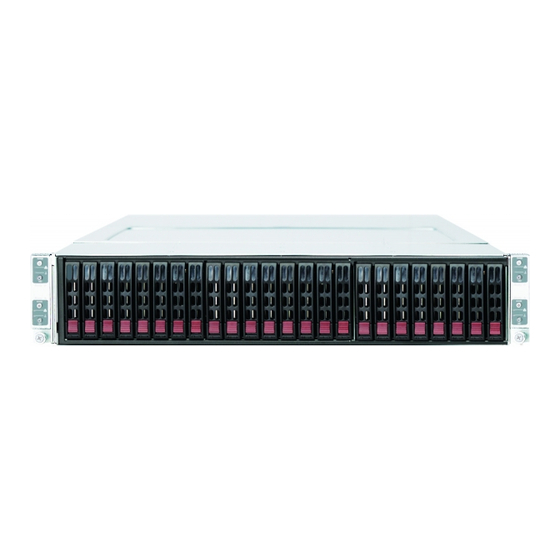
SUPERSERVER 2026TT-HxRF User's Manual Figure 6-1. Chassis Front View Node B Control Panel Node D Control Panel SAS/SATA Drives Node A Control Panel Node C Control Panel Figure 6-2. Chassis Rear View Dedicated IPMI LAN Port Dedicated IPMI LAN Port LAN Ports PCI-Express x16 Slot Power Supply... -
Page 61: Fan Confi Guration
Chapter 6: Advanced Chassis Setup Fan Confi guration In the 2U Twin, each node (serverboard) controls the two fans that reside on its side of the chassis. This means that two nodes will share control for two fans. If the fan speed settings in BIOS are different for these two nodes, the BIOS setting with the higher fan speed will apply. -
Page 62: Hard Drive Installation/Removal
SUPERSERVER 2026TT-HxRF User's Manual Hard Drive Installation/Removal Overview The hard drives are mounted in drive carriers to simplify their installation and removal from the chassis. These carriers also help promote proper airfl ow for the system. For this reason, even empty carriers without drives installed must remain in the chassis. - Page 63 Chapter 6: Advanced Chassis Setup Figure 6-3. Mounting a Hard Drive in a Carrier Installing/Removing Hot-swap Drives To remove a carrier, push the release button located beside the drive LEDs. Swing the handle fully out and use it to pull the unit straight out (see Figure 6-4).
- Page 64 SUPERSERVER 2026TT-HxRF User's Manual Figure 6-4. Removing a Hard Drive Figure 6-5. Drives and Nodes: Logical Confi guration Note: see Figure 6-1 for the locations of the control panels that are associated with each node.
-
Page 65: Node Installation/Removal
Chapter 6: Advanced Chassis Setup Node Installation/Removal As with any server system, power must be removed from the serverboard when upgrading or installing memory or processors. In the 2U Twin server, the server- boards (nodes) are capable of being hot-swapped from the chassis, allowing one to be powered down for servicing while the other continues operating. - Page 66 SUPERSERVER 2026TT-HxRF User's Manual Figure 6-7. Removing a System Node Note: numbers correspond to the procedural steps as described on the previous page.
-
Page 67: Installing The Air Shrouds
Chapter 6: Advanced Chassis Setup Installing the Air Shrouds Air Shrouds Air shrouds concentrate airfl ow to maximize fan effi ciency. The SC217 chassis air shroud does not require screws to set up. Four identical air shrouds are required, one in each serverboard drawer. Installing an Air Shroud Confi... - Page 68 SUPERSERVER 2026TT-HxRF User's Manual Figure 6-8. Removing the Power Supply Release Tab 6-10...
-
Page 69: Chapter 7 Bios
Chapter 7: BIOS Chapter 7 BIOS Introduction This chapter describes the AMI BIOS Setup Utility for the X8DTT-HF+/HIBXF+/ HIBQF+. The AMI ROM BIOS is stored in a Flash EEPROM and can be easily updated. This chapter describes the basic navigation of the AMI BIOS Setup Utility setup screens. -
Page 70: Starting The Setup Utility
SUPERSERVER 2026TT-HxRF User's Manual Starting the Setup Utility Normally, the only visible Power-On Self-Test (POST) routine is the memory test. As the memory is being tested, press the <Delete> key to enter the main menu of the AMI BIOS Setup Utility. From the main menu, you can access the other setup screens. - Page 71 Chapter 7: BIOS Day MM/DD/YY format. The time is entered in HH:MM:SS format. (Note: The time is in the 24-hour format. For example, 5:30 P.M. appears as 17:30:00.) Supermicro X8DTT/-F/-IBX/-IBXF/-IBQ/-IBQF BIOS Build Version This item displays the BIOS revision used in your system. BIOS Build Date This item displays the date when this BIOS was completed.
-
Page 72: Advanced Setup Confi Gurations
SUPERSERVER 2026TT-HxRF User's Manual Advanced Setup Confi gurations Use the arrow keys to select Boot Setup and hit <Enter> to access the submenu items: BOOT Features Quick Boot If Enabled, this option will skip certain tests during POST to reduce the time needed for system boot. -
Page 73: Processor And Clock Options
Chapter 7: BIOS Hit 'Del' Message Display This feature displays "Press DEL to run Setup" during POST. The options are Enabled and Disabled. Interrupt 19 Capture Interrupt 19 is the software interrupt that handles the boot disk function. When this item is set to Enabled, the ROM BIOS of the host adaptors will "capture"... - Page 74 SUPERSERVER 2026TT-HxRF User's Manual C1E Support Select Enabled to use the feature of Enhanced Halt State. C1E signifi cantly reduces the CPU's power consumption by reducing the CPU's clock cycle and voltage during a "Halt State." The options are Disabled and Enabled. Hardware Prefetcher (Available when supported by the CPU) If set to Enabled, the hardware pre fetcher will pre fetch streams of data and instruc- tions from the main memory to the L2 cache in the forward or backward manner to...
-
Page 75: Advanced Chipset Control
Chapter 7: BIOS tion and heat dissipation. Please refer to Intel’s web site for detailed information. The options are Disable (Disable GV3) and Enable (Enable GV3). Intel® TurboMode Technology Select Enabled to use the Turbo Mode to boost system performance. The options are Enabled and Disabled. - Page 76 SUPERSERVER 2026TT-HxRF User's Manual QPI L0s and L1 This enables the QPI power state to low power. L0s and L1 are automatically selected by the motherboard. The options are Disabled and Enabled. Memory Frequency This feature forces a DDR3 frequency slower than what the system has detected. The available options are Auto, Force DDR-800, Force DDR-1066, and Force DDR-1333.
- Page 77 Chapter 7: BIOS Throttling - Closed Loop/Throttling - Open Loop Throttling improves reliability and reduces power in the processor by automatic voltage control during processor idle states. Available options are Disabled and Enabled. If Enabled, the following items will appear: Hysteresis Temperature Temperature Hysteresis is the temperature lag (in degrees Celsius) after the set DIMM temperature threshold is reached before Closed Loop Throttling...
- Page 78 SUPERSERVER 2026TT-HxRF User's Manual North Bridge Confi guration This feature allows the user to confi gure the settings for the Intel IOH chip. Crystal Beach/DMA (Direct Memory Access) This feature works with the Intel I/O AT (Acceleration Technology) to accelerate the performance of TOE devices.
- Page 79 Chapter 7: BIOS USB 2.0 Controller Select Enabled to activate the onboard USB 2.0 controller. The options are Enabled and Disabled. USB 2.0 Controller Mode This setting allows you to select the USB 2.0 Controller mode. The options are Hi-Speed (480 Mbps) and Full Speed (12 Mbps). BIOS EHCI Hand-Off Select Enabled to enable BIOS Enhanced Host Controller Interface support to provide a workaround solution for an operating system that does not have EHCI...
- Page 80 SUPERSERVER 2026TT-HxRF User's Manual Hot Plug (This feature is available when the option-Enabled is selected) Select Enable to enable the hot plug function for the SATA devices. The options are Enabled and Disabled. SATA#2 Confi guration Selecting Enhanced will set SATA#2 to native SATA mode. The options are Disabled, and Enhanced.
- Page 81 Chapter 7: BIOS Select 0 to allow the AMI BIOS to use PIO mode 0. It has a data transfer rate of 3.3 MBs. Select 1 to allow the AMI BIOS to use PIO mode 1. It has a data transfer rate of 5.2 MBs.
- Page 82 SUPERSERVER 2026TT-HxRF User's Manual Select UDMA5 to allow the BIOS to use Ultra DMA mode 5. It has a data transfer rate of 133 MBs. Select UDMA6 to allow the BIOS to use Ultra DMA mode 6. It has a data transfer rate of 133 MBs.
- Page 83 Chapter 7: BIOS Load Onboard LAN1 Option ROM/Load Onboard LAN2 Option ROM Select Enabled to enable the onboard LAN1 or LAN2 Option ROM. This is to boot computer using a network interface. The options are Enabled and Disabled. Super IO Device Confi guration Serial Port1 Address/ Serial Port2 Address This option specifi...
-
Page 84: Hardware Health Monitor
SUPERSERVER 2026TT-HxRF User's Manual Terminal Type This feature allows the user to select the target terminal type for Console Redirec- tion. The options are ANSI, VT100, and VT-UTF8. VT-UTF8 Combo Key Support A terminal keyboard defi nition that provides a way to send commands from a remote console. - Page 85 Chapter 7: BIOS CPU Temperature/System Temperature This feature displays current temperature readings for the CPU and the System. The following items will be displayed for your reference only: CPU Temperature The CPU thermal technology that reports absolute temperatures (Celsius/Fahr- enheit) has been upgraded to a more advanced feature by Intel in its newer processors.
- Page 86 SUPERSERVER 2026TT-HxRF User's Manual User intervention: If the system buzzer and Overheat LED has activated, take action immediately by checking the system fans, chassis ventilation and room temperature to correct any problems. Notes: The system may shut down if it continues for a long period to prevent damage to the CPU.
- Page 87 Chapter 7: BIOS APIC ACPI SCI IRQ When this item is set to Enabled, APIC ACPI SCI IRQ is supported by the system. The options are Enabled and Disabled. Headless Mode This feature is used to enable system to function without a keyboard, monitor or mouse attached The options are Enabled and Disabled.
-
Page 88: View Bmc System Event Log
SUPERSERVER 2026TT-HxRF User's Manual View BMC System Event Log This feature displays the BMC System Event Log (SEL). It shows the total num- ber of entries of BMC System Events. To view an event, select an Entry Number and pressing <Enter> to display the information as shown in the screen. •... - Page 89 Chapter 7: BIOS IP Address Source Select the source of this machine's IP address. If Static is selected, you will need to know and enter manually the IP address of this machine below. If DHCP is selected, the BIOS will search for a DHCP (Dynamic Host Confi guration Protocol) server in the network it is attached to, and request the next available IP address.
- Page 90 SUPERSERVER 2026TT-HxRF User's Manual Subnet Mask This item displays the current subnet mask setting for your IPMI connection. Current Subnet Mask in BMC This item displays the current subnet mask used for your IPMI connection. Gateway Address Confi guration Enter the gateway address for this machine. This should be in decimal and in dotted quad form (i.e., 192.168.10.253).
-
Page 91: Security Settings
Chapter 7: BIOS DMI Event Log View Event Log Use this option to view the System Event Log. Mark all events as read This option marks all events as read. The options are OK and Cancel. Clear event log This option clears the Event Log memory of all messages. The options are OK and Cancel. -
Page 92: Boot Confi Guration
SUPERSERVER 2026TT-HxRF User's Manual Password Check This item allows you to check a password after it has been entered. The options are Setup and Always. Boot Sector Virus Protection When Enabled, the AMI BOIS displays a warning when any program (or virus) is- sues a Disk Format command or attempts to write to the boot sector of the hard disk drive. -
Page 93: Hard Disk Drives
Chapter 7: BIOS Hard Disk Drives This feature allows the user to specify the boot sequence from all available hard disk drives. The settings are Disabled and a list of all hard disk drives that have been detected (i.e., 1st Drive, 2nd Drive, 3rd Drive, etc). •... -
Page 94: Exit Options
SUPERSERVER 2026TT-HxRF User's Manual Exit Options Select the Exit tab from the AMI BIOS Setup Utility screen to enter the Exit BIOS Setup screen. Save Changes and Exit When you have completed the system confi guration changes, select this option to leave the BIOS Setup Utility and reboot the computer, so the new system con- fi... - Page 95 Chapter 7: BIOS How to Recover the AMIBIOS Image (the Main BIOS Block) An AMIBIOS fl ash chip consists of a boot sector block, and a main BIOS code block (a main BIOS image). The boot sector block contains critical BIOS code, including memory detection and recovery code to be used to fl...
- Page 96 SUPERSERVER 2026TT-HxRF User's Manual Boot Sector Recovery from a Serial Port ("Serial Flash") This process, also known as "Serial Flash," allows the user to use a serial port to load a BIOS image for Boot Sector recovery. This feature is usually used for embed- ded systems that rely on a serial port for remote access and debugging.
- Page 97 Chapter 7: BIOS 4. Power on your system and click the <Connect> button in the Hyper Terminal. The terminal screen will display the following messages. 5. Following the instructions given on the screen to update the BIOS. These instructions are also shown below. a.
- Page 98 SUPERSERVER 2026TT-HxRF User's Manual 6. Once you've completed the instructions given, a screen will display to indicate that remote fl ashing is starting and the new BIOS fi le is being uploaded. 7. To use Hyper Terminal to transfer the XModem protocol by using the "Send File"...
-
Page 99: Appendix A Bios Error Beep Codes
Appendix A: BIOS Error Beep Codes Appendix A BIOS Error Beep Codes During the POST (Power-On Self-Test) routines, which are performed each time the system is powered on, errors may occur. Non-fatal errors are those which, in most cases, allow the system to continue the boot-up process. - Page 100 SUPERSERVER 2026TT-HxRF User's Manual Notes...
-
Page 101: Appendix B Installing Windows
Appendix B: Installing Windows Appendix B Installing Windows After all hardware components have been installed, you must fi rst confi gure Intel South Bridge RAID Settings before you install the Windows OS and other software drivers. To confi gure RAID settings, please refer to RAID Confi guration User Guides posted on our web site at www.supermicro.com/support/manuals. - Page 102 SUPERSERVER 2026TT-HxRF User's Manual B-2 Installing Windows for a Non-RAID System Insert Microsoft's Windows XP/2003 Setup CD in the CD drive and the system will start booting up from CD. Continue with the OS installation. The Windows OS Setup screen will display. From the Windows XP/2003 Setup screen, press the <Enter>...
-
Page 103: Appendix C System Specifi Cations
Appendix C: System Specifi cations Appendix C System Specifi cations Note: unless noted specifi cations apply to a complete system (four server- boards). Processors Four Intel® 5600/5500 Series processors in LGA1366 sockets Note: Please refer to our website for details on supported processors. Chipset Intel 5520/ICH10R BIOS... - Page 104 SUPERSERVER 2026TT-HxRF User's Manual Serverboard 2026TT-HTRF: X8DTT-HF+ 2026TT-HIBXRF: X8DTT-HIBXF+ 2026TT-HIBQRF: X8DTT-HIBQF+ 2026TT-H6RF: X8DTT-HEF+ 2026TT-H6BXRF: X8DTT-HIBXF+ 2026TT-H6IBQRF: X8DTT-HIBQF+ Dimensions (all): 16.64" (L) x 6.80" (W) (422.66 mm x 172.72 mm) Chassis SC217HQ-R1400BP (2U Rackmount) Dimensions: (WxHxD) 17.2 x 3.5 x 28.5 in. (437 x 89 x 724 mm) Weight Gross Weight: 85 lbs.
- Page 105 Appendix C: System Specifi cations Regulatory Compliance Electromagnetic Emissions: FCC Class A, EN 55022 Class A, EN 61000-3-2/- 3-3, CISPR 22 Class A Electromagnetic Immunity: EN 55024/CISPR 24, (EN 61000-4-2, EN 61000-4-3, EN 61000-4-4, EN 61000-4-5, EN 61000-4-6, EN 61000-4-8, EN 61000-4-11) Safety: CSA/EN/IEC/UL 60950-1 Compliant, UL or CSA Listed (USA and Canada), CE Marking (Europe) California Best Management Practices Regulations for Perchlorate Materials:...
- Page 106 SUPERSERVER 2026TT-HxRF User's Manual (continued from front) The products sold by Supermicro are not intended for and will not be used in life support systems, medical equipment, nuclear facilities or systems, aircraft, aircraft devices, aircraft/emergency com- munication devices or other critical systems whose failure to perform be reasonably expected to result in signifi...
Need help?
Do you have a question about the SuperServer 2026TT-HTRF and is the answer not in the manual?
Questions and answers