
Related Manuals for A-Neuvideo HD-44G


Summary of Contents for A-Neuvideo HD-44G
- Page 1 HD-44G 4x4 HDMI MATRIX SWITCHER INSTRUCTION MANUAL A-NeuVideo.com | Frisco, Texas 75034 (317) 456-2461...
-
Page 2: Safety Information
SAFETY INFORMATION To ensure the best results from this product, please read this manual and all other documentation before operating your equipment. Retain all documentation for future reference. Follow all instructions printed on unit chassis for proper operation. To reduce the risk of fi re, do not spill water or other liquids into or on the unit, or operate the unit while standing in liquid. Make sure power outlets conform to the power requirements listed on the back of the unit. -
Page 3: Table Of Contents
The HD-44G is professional 4x4 matrix routing switch. Supporting • Use only the supplied power supply unit (PSU). Do not use the four (4) HDMI Inputs. Output supported (4) HDMI. The HD-44G is PSU if it is damaged. based on the HDMI standard and supports full resolution HDMI •... -
Page 4: Features & Specifications
FEATURES FEATURES • 4x HDMI digital source devices matrix switched to 4x HDMI devices • HDMI digital video w/embedded audio, DVI format and CEC/HDCP 2.0 compliant • Seven (7) function key control and worldwide EDID modes for HDTV resolutions • Link speeds of up to 6.75 Gbps (link clock rate of 225Mb Hz), Support HDMI 1.4a 3D formats •... -
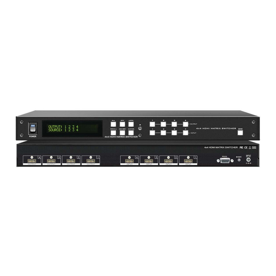
Page 5: Front Panel
FRONT PANEL FRONT PANEL POWER SWITCH The power switch turns the unit on and off. The LED will illuminate red to indicate that the switcher is ON and is receiving power. The Switcher will remember that last state during a power cycle. When power is removed and resorted, the last confi... - Page 6 FRONT PANEL FRONT PANEL FUNCTION KEY - OFF Disables (mute) video to selected channels. Either destinations. - Press OFF button followed by any Destination channel. - Press 1 thru 4 output destination. The display will show ” 0 “ for the selected channel indicating no video selected. FUNCTION KEY - RECALL The system will show previously stored presets, up to a total of 8.
- Page 7 FRONT PANEL FRONT PANEL FUNCTION KEY - MEMORY The system will show store presets, up to a total of 8. Presets are stored in local memory using Source keys 1 thru 4 or Destination keys 1 thru 4 as the memory preset location. - Confi...
-
Page 8: Rear Panel
REAR PANEL REAR PANEL DC POWER INLET The Switcher is fi tted with a DC power plug input connector. Ensure Power Jack: that the used is of an approved type and is of suffi cient current DC Jack - Inner OD ᴓ 2.1mm (+ ) carrying connector capacity with the correct voltage and connector Outside OD ᴓ... -
Page 9: Typical Application
TYPICAL APPLICATION INSTALLING DIAGRAM Sample connection using RS-232 serial interface or IR External in to control switch (HD-44G). NOTE: 1. Control Projector Over CAT5e/6/7 Extender: HD-6335T: HDBaseT HDMI CAT5e/6/7 Transmitter HD-6335R: HDBaseT HDMI CAT5e/6/7 Receiver 2. Preview Output : Picture as same OUTPUT-1 3. - Page 10 TYPICAL APPLICATION INSTALLING DIAGRAM Sample connection using Audio Extractor to Audio Amplifi er and ARC Control Box link TV Return Audio to Audio Device, Control a Satellite Receiver source via HDBaseT Transmitter (HD-6335T) and HDBaseT Receiver (HD-6335R). NOTE: 1. Control Satellite Receiver Over HDMI CAT5e/6/7 Extender from room: HD-6335T: HDBaseT HDMI Transmitter HD-6335R: HDBaseT HDMI Receiver...
-
Page 11: Remote Control
REMOTE CONTROL Before making any connections to the switcher. Observe the following: > Ensure the mains voltage supply matches the label on the > Connect all audio video sources and destination equipment supplied plug-pack (+/- 10%) > Power up all source and destination audio-visual sources >... - Page 12 REMOTE CONTROL IR REMOTE CUSTOM AND DATA CODES (NEC STANDARD) HOW TO SETUP IR CODES : Model number : HD-44G CUSTOM CODE : 837C POWER ON : 837C A15E POWER OFF : 837C A25D ALL : 837C B04F OFF :...
-
Page 13: Ir Extender
IR EXTENDER IR RECEIVER: 1. SB-100 IR 300M Receiver Device Cable (3C) IR Receiver (SB-100) R oHS /95/E C INP UT R S -232 IR E XT. in DC 12V IR Rx RS - 232 IR EXT . SB-100 SB-100 IR Receiver Set SB-100 Maximum Distance ~ 984 feet (300 meters) 2. - Page 14 IR EXTENDER IR EMITTER: 1. SB-101 IR 300M Transmitter Device Cable (3C) IR Transmitter (SB-101) IR out IR in CAT6/6a/7 DC 12V R oHS /95/E C IR Tx From OUTPUT Receiver Receiver SB-101 SB-101 IR Transmitter Set SB-101 Maximum Distance ~ 984 feet (300 meters) 2.
-
Page 15: Edid Function
EDID FUNCTION EDID FUNCTION SETUP EDID setup To change the EDID setup Step 1. Press the EDID button The display will show the currently selected EDID mode Step 2. Press SOURCE #1 or #2 button row The button will fl ash blue and the display will show the current Embedded EDID Status. - Page 16 EDID FUNCTION NOTE : The already learned EDID cannot be modifi ed. You can only rebuild a new Learning EDID. For example: When the Source has “Learned” the EDID data from a destination, It will save that EDID information into EPROM and the EDID data cannot change.
- Page 17 EDID FUNCTION EDID FUNCTION : LEARNING Learning EDID Single to Single Example : Learn Destination #4 EDID To Source #3. The button will fl ash blue and the display will show the current Embedded EDID Press the EDID button Step 1. Status.
-
Page 18: Rs-232 Serial Interface
RS-232 RS-232 SERIAL INTERFACE PROTOCOL COMMANDS ( Ethernet / RS-232 Control driver V2.0 ) The HD-44G switcher can be controlled via the RS-232 serial control port to allow for interfacing to a PC, or similar third party control system. The serial communication parameters are 9600 baud, 8 bit, No Parity and 1 stop bit - this is often referred to as 9600 8N1. When the unit... -
Page 19: Ethernet Serial Interface
ETHERNET SERIAL INTERFACE ETHERNET SERIAL INTERFACE CONNECT A PC OR CONTROL SYSTEM. VERSION COMPATIBLE V2.0 For a complete list of commands, please reference external document extended Ethernet Protocol Instruction Manual. ETHERNET SERIAL INTERFACE Pin Ethernet Reference TXOP TX + TXON TX - RXIP RX +... - Page 20 BY, THROUGH OR UNDER A-NeuVideo, INC (COLLECTIVELY, THE “PRODUCT”). By using installing or using the Product, you unconditionally signify your agreement to these Terms and Conditions. If you do not agree to these Terms and Conditions, do not use the Product and return the Product to A-NeuVideo, Inc. at the return address set forth on the Product’s packing label at your expense.
Need help?
Do you have a question about the HD-44G and is the answer not in the manual?
Questions and answers