
Related Manuals for A-Neuvideo ANI-VGA404


Summary of Contents for A-Neuvideo ANI-VGA404
- Page 1 CUSTOM MATRIX SWITCHERS INSTRUCTION MANUAL VGA Serial Matrix Switches RGB Serial Matrix Switches AV Serial Matrix Switches A-NeuVideo.com | Frisco, Texas 75034 469-277-7606 V.2.3...
- Page 2 SAFETY INFORMATION To ensure the best results from this product, please read this manual and all other documentation before operating your equipment. Retain all documentation for future reference. Follow all instructions printed on unit chassis for proper operation. To reduce the risk of fire, do not spill water or other liquids into or on the unit, or operate the unit while standing in liquid. Make sure power outlets conform to the power requirements listed on the back of the unit.
-
Page 3: Table Of Contents
INTRODUCTION TABLE OF CONTENTS SAFETY PRECAUTIONS INTRODUCTION ............... 2 Please read all instructions before attempting to unpack, install or operate this equipment and before connecting the power supply. SWITCHER CATEGORY ..........2 Please keep the following in mind as you unpack and install this PACKAGE CONTENTS ........... -
Page 4: Introduction
INTRODUCTION / SWITCHER CATEGORY / CONTENTS INTRODUCTION Matrix switch is a high-performance matrix switcher designed for video and audio signal routing. It supports unbalanced audio, Composite, RGBHV (Component), or VGA (DB15). The excellent quality of this series of matrix switchers comes from using the industry’s best performing IC chips and we design each switcher to ensure the highest signal quality. -
Page 5: Types Of Matrix Switchers
TYPES OF MATRIX SWITCHERS Input # of Output # of Model# Signal Type Connection Type Inputs Connection Type Outputs ANI-VGA404 HD15 HD15 ANI-VGA404A VGA w/Audio HD15 & Terminal HD15 & Terminal ANI-VGA801 HD15 HD15 ANI-VGA801-A VGA w/Audio HD15 & Terminal HD15 &... -
Page 6: Composite Video
TYPES OF MATRIX SWITCHERS COMPOSITE VIDEO Input # of Output # of Model# Signal Type Connection Type Inputs Connection Type Outputs ANI-V404-A Composite Video w/Audio ANI-V801-A Composite Video w/Audio ANI-V802-A Composite Video w/Audio ANI-V804-A Composite Video w/Audio ANI-V808-A Composite Video w/Audio ANI-V1602-A Composite Video w/Audio ANI-V1604-A... -
Page 7: Rgb/Hv
TYPES OF MATRIX SWITCHERS RGB/HV Input # of Output # of Model# Signal Type Connection Type Inputs Connection Type Outputs ANI-RGB404 RGB/HV ANI-RGB404-A RGB/HV w/Audio BNC & Terminal BNC & Terminal ANI-RGB802 RGB/HV ANI-RGB802-A RGB/HV w/Audio BNC & Terminal BNC & Terminal ANI-RGB804 RGB/HV ANI-RGB804-A... -
Page 8: Audio Connections
AUDIO CONNECTIONS The series matrix switchers with audio input/output supports unbalanced. Figure 1: Unbalanced Input/Output audio connection... -
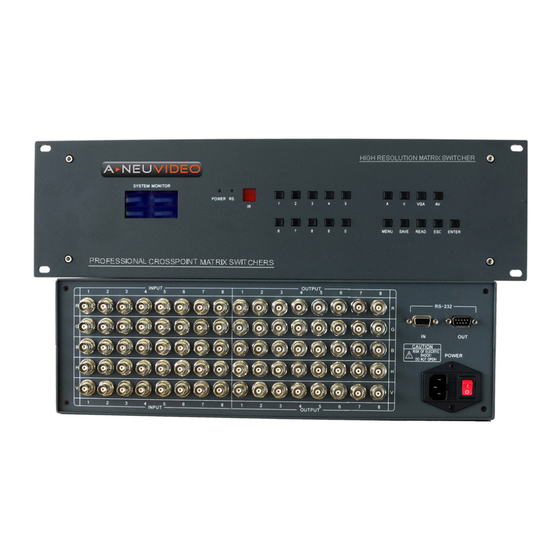
Page 9: Vga Matrix Switcher
VGA MATRIX SWITCHER Figure 2: ANI-VGA1608A FRONT PANEL Figure 3: ANI-VGA1608A REAR PANEL FEATURES • Professional matrix chip with 350MHz (-3dB) bandwidth when fully loaded • Supports HDTV up to 2048x1536 60Hz refresh rate and 1280x1024 120Hz refresh rate • The switching status can be read directly from the LCD display •... -
Page 10: Specifications
VGA MATRIX SWITCHER VGA SPECIFICATIONS Input & Output: 15HD-F Standard VGA 350MHz (-3dB) Bandwidth: 0-10MHz (+0.2dB to -0.1dB) 0-120MHz (+6.5dB to -1.0dB) Input Level: 0.5Vp-p min, 2.0Vp-p max VGA Port Input I/O Impedance: 75Ω Brightness Color Interfere: -68.5dB@5MHz Echo Wasting: -85dB@10MHz SNR (S/N): 72.8dB... -
Page 11: Rgb Matrix
RGB/HV MATRIX SWITCHER Figure 4: ANI-RGB808 FRONT PANEL Figure 5: ANI-RGB808 REAR PANEL FEATURES • Professional matrix chip with 350MHz (-3dB) bandwidth when fully loaded • Supports HDTV up to 2048x1536 60Hz refresh rate and 1280x1024 120Hz refresh rate • The switching status can be read directly from the LCD display •... -
Page 12: Specifications
RGB/HV MATRIX SWITCHER RGB SPECIFICATIONS Input & Output: Standard BNC 350MHz (-3dB) Bandwidth: 0-10MHz (+0.2dB to -0.1dB) 0-120MHz (+6.5dB to -1.0dB) Input Level: 0.5Vp-p min, 2.0Vp-p max RGB Port Input I/O Impedance: 75Ω Brightness Color Interfere: -68.5dB@5MHz Echo Wasting: -85dB@10MHz SNR (S/N): 72.8dB Switch Speed:... -
Page 13: Composite Video Switcher
COMPOSITE VIDEO SWITCHER Figure 4: ANI-RGB808 FRONT PANEL Figure 5: ANI-RGB808 REAR PANEL FEATURES • Professional matrix chip with 100MHz (-3dB) bandwidth when fully loaded • The switching status can be read directly from the LCD display • Remote control via front panel push buttons or RS-232 •... -
Page 14: Specifications
COMPOSITE VIDEO SWITCHER COMPOSITE VIDEO SPECIFICATIONS Input & Output: BNC connector 100MHz (-3dB) Bandwidth: 0.5Vp-p Min, 2.0Vp-p Max 75Ω Input Level: 1.0Vp-p Min, 2.0Vp-p Max RGB Port Input I/O Impedance: 75Ω Brightness Color Interfere: 75dB Echo Wasting: 0.23% SNR (S/N): 72.8dB Switch Speed: Up to 100ns... -
Page 15: Operation
OPERATION PRESS KEY OF FUNCTION REGION Stands for Audio when switch Stands for saving the current status switching Stands for Video when switch Stands for reading saved status switching Stands for VGA Model when switch Cancel Stands for Audio synchronize with Video when switch Ascertain Stands for into device menu NOTE OF FUNCTION KEY... - Page 16 OPERATION “READ”: Call the saved input & output connection e.g.1: Press “READ” +“2” +“ENTER” means saving the current status of input & output to storage location 2 while the total up to 30. “MENU”: To set baud, addr, beep and cycle The LCD shows four choices “1”For Setting Baud Operation: Press “MENU”...
-
Page 17: Panel Switch
PANEL SWITCH OPERATION FORMAT OF INPUT & OUTPUT SWITCH Way like this: “input”+”switch model”+”output”+”enter” Input: 9 number on the panel, also can combined two or three numbers together to choose double or triple digital. Switch Model: “A”,”AV”,”V”,”VGA” means switching computer & audio/ computer /Audio Output: 9 number on the panel, also can combined two or three numbers together to choose double or triple digital. -
Page 18: Protocol Of Serial Port And Command Code
PROTOCOL OF SERIAL PORT AND COMMAND CODE Before using the serial port to control the device, please confirm the following configuration: FACTORY DEFAULT SETTING FOR RS-232 Baud Rate: 9600bps Data bit: 8 bits Parity: None Stop Bits: Flow Control: None Use a straight RS-232 cable. -
Page 19: Ascii Code
PROTOCOL OF SERIAL PORT AND COMMAND CODE Definition of RS-232 Port COM IN (D-SUB9F) Definition of RS-232 Port COM OUT (D-SUB9M) Name Description Name Description Not used Not used Transferring data Receiving data Transferring data Receiving data Not used Not used Signal ground Signal ground Not used... -
Page 20: Code Examples
PROTOCOL OF SERIAL PORT AND COMMAND CODE CODE EXAMPLES 1. Switch an input port to all output ports: [x1]All. e.g. : The code to switch input port 3 to all output ports is “3All.” 2. Switch all input ports to corresponding output ports: All#. e.g. - Page 21 SOFTWARE OPERATION INSTRUCTION SOFTWARE OPERATION INSTRUCTION 1. Run the software and the interface is as following: 2. Right click “Matrix Fix” and menu appears like 3. Click “Add Device”, a dialog appears. Select serial port number, baud rate and address.
-
Page 22: Operation Of Software
SOFTWARE OPERATION INSTRUCTION “OK” 4. Click to connect the device. After receiving device information, the controlling Interface is done The left bar displays the name and type of the device connected. The name can be renamed. Right click on the name, a pop menu appears: Click “Delete Device”... - Page 23 SOFTWARE OPERATION INSTRUCTION “Port Name” Click to change the names of input & output and preset groups. The interface is as following: Click “OK” to save changes. The caption of button on the interface is also changed as shown below: 5.
- Page 24 SOFTWARE OPERATION INSTRUCTION 6. Users can switch the input port to more output ports in one time as shown below: The above operation switches input port 8 to output port 1, 2, 4, 10 and 19 in one time. Click “OK”...
- Page 25 SOFTWARE OPERATION INSTRUCTION 7. Click “Save”, “Read” to operate preset groups. There are altogether 30 preset groups as shown below:...
- Page 26 BY, THROUGH OR UNDER A-NeuVideo, INC (COLLECTIVELY, THE “PRODUCT”). By using installing or using the Product, you unconditionally signify your agreement to these Terms and Conditions. If you do not agree to these Terms and Conditions, do not use the Product and return the Product to A-NeuVideo, Inc. at the return address set forth on the Product’s packing label at your expense.
Need help?
Do you have a question about the ANI-VGA404 and is the answer not in the manual?
Questions and answers