Table of Contents
Advertisement
Quick Links
Advertisement
Table of Contents

Subscribe to Our Youtube Channel
Related Manuals for E.C.A. Fortius


Summary of Contents for E.C.A. Fortius
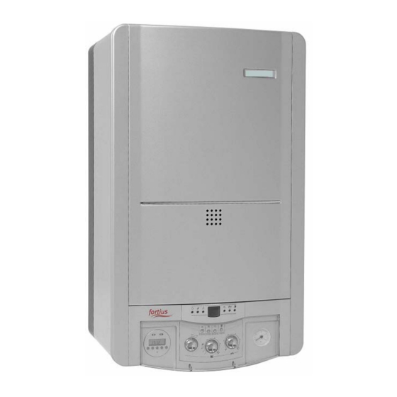
- Page 1 24 kW Open Flued Gas Combination Boiler (bithermic type) 24 kW Room Sealed Fan Assisted Gas Combination Boiler (bithermic type) 24 kW Room Sealed Fan Assisted Gas Combination Boiler (monothermic type) 28 kW Room Sealed Fan Assisted Gas Combination Boiler (monothermic type) SERVICE MANUAL...
- Page 2 CONTENTS PRODUCT Product Notation Safety Systems Technical Data Main Components Operating Functions GAS TYPE CONVERSION Gas Pressure Adjustments Replacement Of The Burner Injectors Jumper Adjustment ADJUSTMENTS Service Setting Mode Chimney Sweep Push-Button PB4 FAULT & FAILURE...
- Page 3 DHW safety stop function Technical Data Fortius 24 kW open flued gas combination boiler (FO 24 BB) is B type boiler (DIN EN 297). B type boilers have an open combustion chamber. Combustion air is provided from the installation room and products of combustion is discharged by means of approved flue ducts connections and a chimney.
- Page 4 Table 2 FO 24 BB FO 24 HB FO 24 HM FO 28 HM Unit Gas Category* 2H 3+ 2H 3+ 2H 3+ 2H 3+ Boiler Type 11 BS Type of gas Natural gas Natural gas Natural gas Natural gas Performances , Min.
- Page 5 Main Components Table 3a FO 24 BB FO 24 HB Microcontroller Board Microcontroller Board Bitermic (Main Board) Bitermic (Main Board) User Interface User Interface Gas Valve Gas Valve Burner (13 blade) Burner (13 blade) 24 kW Heat Exchanger 24 kW Heat Exchanger (bithermic) (bithermic) Hydroblock (bithermic)
- Page 6 Table 3b FO 24 HM FO 28 HM Microcontroller Board Microcontroller Board Monotermic Monotermic (Main Board) (Main Board) User Interface User Interface Gas Valve Gas Valve Burner (13 blade) Burner (15 blade) 24 kW Heat Exchanger 28 kW Heat Exchanger (monothermic) (monothermic) Hydroblock...
- Page 7 MICROCONTROLLER BOARD (MAIN BOARD) The main board operates on 230 VAC, 50 Hz and drives gas valve, fan, pump and (in monothermic types) 3 way electric valve. Dynamic air pressure test takes place before every ignition cycle. Limit thermostat ensures extra safety level. Flame in the burner is checked regularly. The main board provides all the functionality and safety of the boiler.
- Page 8 Wiring Diagrams fig. 1a...
- Page 9 fig. 1b...
- Page 10 fig. 1c...
- Page 11 Tablo 4 Technical and Functional Specifications General Power supply range: 230 Vac -15% +10% Power supply frequency: 50 Hz ± % 2 Power consumption: 5 VA Max. admitted humidity: 90% @ 40 °C (non condensing) Working temperature range: -20 °C … 60 °C Electrical rating Fusing: Fan output:...
- Page 12 Tablo 4 Technical and Functional Specifications Timing Pre purge time: 0 sec Waiting time: 0 sec Pre ignition time: 2 sec Safety time: 7 sec Number of retrials: Flame failure response time: 1 sec Post ignition time: 0,4 sec Post purge time: 0,8 sec Pump over-run time: A) for DHW...
-
Page 13: Gas Valve
Tablo 4 Technical and Functional Specifications Other Specifications Nr. of electrodes: 2 for flame ignition and one for detection Flame sensing cable and spark cable: max. 0,5 m External components (except heat demand): max 0,5 m Remote reset: max. of 5 reset in 15 minutes CH water SET temperature range 40 °C …... - Page 14 fig. 2 Gas Valve BURNER The gas coming from the gas valve is fired in the burner. 13 blade burners are used in 24 kW boilers while 15 blade burners are used in 28 kW boilers. Some of the common specifications of these two burners are shown in the table below.
-
Page 15: Heat Exchanger
HEAT EXCHANGER Heat exchanger is the component which enables transferring the energy produced by the burning of the gas to the water circuit. Different heat exchangers are used in bithermic (24 kW) and monothermic (24 / 28 kW) models. In bithermic heat exchangers which have two water inlets and two water outlets, both central heating and domestic hot water circuits are heated. - Page 16 fig. 4b Monothermic Heat Exchanger HYDROBLOCK Two different types of hydroblocks are used in bithermic and monothermic types. Hydroblock consists of different components depending on the boiler model. The bithermic hydroblock has pump, pressure relief valve (3 bar), discharge tap, filling tap, water pressure switch and water flow sensor on it.
- Page 17 fig. 5a Bithermic Hydroblock 1 Outlet manifold 2 Inlet manifold 3 By-pass pipe 4 Water flow sensor 5 Filling tap 6 Gasket (G3/4” & G1/2”) 7 Hall effect sensor...
- Page 18 fig. 5b Monothermic Hydroblock 1 3 way electric valve 2 Inlet manifold 3 By-pass pipe 4 Water flow sensor 5 Filling tap 6 Valve motor 7 Valve motor clip 8 Hall effect sensor 9 Bolt 10 Oring 11 By-pass pipe clip...
- Page 19 PUMP Pump enables the central heating water circulation in monothermic and bithermic types. Also in monothermic types, it enables heating the domestic water passing through the plate heat-exchanger by causing the central heating water short circuit circulation. Pump is located on the hydroblock and has 3 speed stages. The pump has expansion vessel and termomanometer connections and also an automatic air vent on it.
- Page 20 PRESSURE RELIEF VALVE (3 BAR) Pressure relief valve (3 bar) protects the central heating circuit and the appliance against increasing pressure. When the pressure in the central heating circuit is over 3 bars, the relief valve functions and decreases the pressure (the outlet tap of the 3 bar relief valve should be connected to the drain line with a plastic hose).
-
Page 21: Plate Heat-Exchanger
fig. 9 Water Pressure Switch PLATE HEAT-EXCHANGER Plate heat-exchanger is the secondary heat-exchanger used in monothermic types for heating the domestic water. In need of domestic hot water, the 3 way electric valve sends the central heating water from the primary heat-exchanger to the plate heat-exchanger. Heat of the central heating water is transferred to the domestic water in the plate heat-exchanger. - Page 22 fig. 11 Water Flow Sensor CENTRAL HEATING AND DOMESTIC HOT WATER (NTC) TEMPERATURE SENSORS The central heating and domestic hot water temperature sensors are NTC (Negative Temperature Coefficient) type. In NTC sensor, temperature and sensor resistance are inversely proportional; the sensor resistance decrease as temperature increases and vice versa.
- Page 23 Table 14 The R-T relation of the NTC sensors α R (Ω) Resistance C) Temperature C) Sensitivity 98660 -5,8 % 56250 -5,4 % 33210 -5,1 % 20240 -4,8 % 12710 -4,5 % 10170 -4,4 % 8194 -4,3 % 5416 -4,0 % 3663 -3,8 % 2530...
-
Page 24: Limit Thermostat
LIMIT THERMOSTAT The limit thermostat used is bimetal type. When water CH from the heat-exchanger exceeds 105°C, the limit thermostat opens and cuts the signal sent to the main board and ensures safety. When the water temperature is below 75 °C, the limit thermostat closes enabling the boiler to operate again after the reset. - Page 25 DIFFERENTIAL AIR PRESSSURE SWITCH (APS) Differential air pressure switch is used in room sealed fan assisted models. It controls the air flow by measuring the pressure differences of the clean air required for burning and flue gas. In case of problems like blockage in the air/flue kit or a strong outer air flow, the air pressure switch shuts down the boiler.
- Page 26 fig. 17 TTB Temperature Sensor Table 17 The R-T relation of the TTB sensor α R (Ω) Resistance C) Temperature C) Sensitivity 97060 -5,8 % 72940 -5,6 % 55319 -5,4 % 42324 -5,3 % 32654 -5,2 % 25396 -5,1 % 19903 -4,8 % 15714...
-
Page 27: Ignition Electrode
Fan enables taking the clean air required for combustion to the combustion chamber and disposing of flue gas in room sealed fan assisted boilers. Table 18 Fan Maximum Power Interior diameter of silicon hose connected to APS 5 mm fig. 18 Fan TERMOMANOMETER Termomanometer displays the water temperature and water pressure of the central heating circuit. -
Page 28: Modes Of Operation
MODES OF OPERATION a) Stand-by Mode: when there is no heat demand for central heating or domestic hot water. b) Domestic Hot Water (DHW) Mode: when there is need for DHW (hot water tap is opened), the hall effect sensor on the water flow sensor detects the water flow and signals the main board for DHW delivery. - Page 29 - Domestic hot water can be obtained between 35°C and 60°C. - Domestic hot water safety temperature is 75°C. If the temperature detected by DHW sensor is above 75°C, DHW operation will stop (burner goes off). - DHW operation is possible even if CH anti-cycling time is active. - During DHW operation, min.-max.
- Page 30 - When there is CH demand, ignition starts and ignition state continues until flame is present. - When the ignition state is over, the boiler will operate in normal modulation and reach the set point within the time defined with slope (°C/min). After that, modulation continues. - If the central heating water temperature exceeds 95°C in CH mode, over temperature error (electronic limit) occurs and the boiler will remain in this error mode till water temperature drops to a safe level (80°C).
- Page 31 - Bithermic & Winter Mode: pump runs for the defined over run time (3sec). This is for transferring the remaining energy to the CH circuit. - Bithermic & Summer Mode: if the temperature detected by the CH temperature sensor is more then 75°C, the pump will run for 1 sec., otherwise it will not run.
-
Page 32: Gas Type Conversion
GAS TYPE CONVERSION : Gas type conversion from LPG to natural gas or from natural gas toLPG must be carried out only by qualified person. - Gas type conversion can be divided in 3 sections: gas pressure adjustments, replacement of the burner injectors and jumper adjusment. - Page 33 fig. 19 Replacement Of The Burner Injectors WARNING:Keep the gas valve on the boiler and electricity supply closed during replacement of the burner injectors. - Shut off the boiler by turning the ON/OFF switch to OFF position and turn off the gas valve on the boiler.
-
Page 34: Gas Leak Test
WARNING: In case of gas leak, fire or explosion hazard, property damage, severe injury or death can happen. Therefore, gas leak test must be performed by qualified person after gas type conversion. GAS LEAK TEST Apply a rich soap and water solution to the surface of all pipe connections. Bubbles indicate a gas leak In case of gas leak, tighten the pipe connection. - Page 35 ADJUSTMENTS LED’s have 6 different signals. The definitions: • ON • OFF • Slow blink: 0.75 sec ON - 0.75 sec OFF • Fast blink: 0.10 sec ON - 0.40 sec OFF • Change blink: 0.75 sec ON - 0.25 sec OFF (it seen when adjusting service setting parameters) •...
- Page 36 Table 22 7 segment display Description after pressing after pressing PB3 twice progressively press: Flame current press: Modulation level press: DHW flow frequency press: Flue temperature (for room sealed type, it's fixed as 25) press: TTB calculated value press: Pump control mode press: Room temperature (if a open therm thermostat connected) press: Software version number for main board (CVBC)
- Page 37 (sec) or it can be adjusted as d1: 0 (sec) for inactive the function. OTC Curve Foot Point Foot point, defines the bottom point of the heating curves (please see page 40 FORTIUS Installation and User’s Operating Instructions), can be adjusted between 10 C …...
- Page 38 Table 24 Parameters No Definition Range Default 40 – 80 CH water SET temperature range ( 35 – 60 DHW SET temperature range ( 3 Minimum power (%) 0 – 30 4 Maximum power (%) 80 – 100 5 Ignition power (%) 20 –...
- Page 39 Chimney Sweep Push-Button PB4 Chimney sweep push-button PB4 has two functions: a) to activate the chimney sweep mode, b) to activate the minimum and maximum running mode without modulation. Chimney Sweep Mode - If the push-button PB4 is pressed more than 3 seconds and less than 5 seconds, chimney sweep mode is activated (fig.
- Page 40 Running mode selection is active. 7 segment display fast fast blink blink Running mode selection is active. 7 segment display fast fast blink blink fig. 22a - Turn the CH potentiometer the minimum position, LED L7 and L9 start blinking to indicate that minimum running is being selected.
- Page 41 Stand – by 7 segment display fig. 22e FAULT & FAILURE Several checks are included to protect the boiler and its environment. In case of error condition, the error code is displayed by 7 segment display (Table 26), and heat demands will be disabled. Error conditions can be divided in 2 groups: lockout conditions and blocking conditions.
- Page 42 Table 26 Error/fault Error/fault definitions codes Flue Gas t 6. Circuit break in flue safety device (NTC) Short circuit in flue safety device (NTC) Flue safety device (NTC) shuts system off because of flue gas leakage Air Flow APS open APS closed Temperatures Over-temperature failure...
Need help?
Do you have a question about the Fortius and is the answer not in the manual?
Questions and answers
Boiler won't fire up red light on flame symbol with line across
The E.C.A. Fortius boiler won't fire up when the red light on the flame symbol is on with a line across because this indicates a lockout condition. Lockout conditions, such as no flame, false flame, over-temperature failure, or APS (Air Pressure Switch) faults, disable heat demands. To clear the lockout, the reset push-button must be held for 2 seconds. If the problem persists, a qualified service technician should be contacted.
This answer is automatically generated
Котел есо фортиус,выдает сначала ошибку 00,потом у1,куда копать