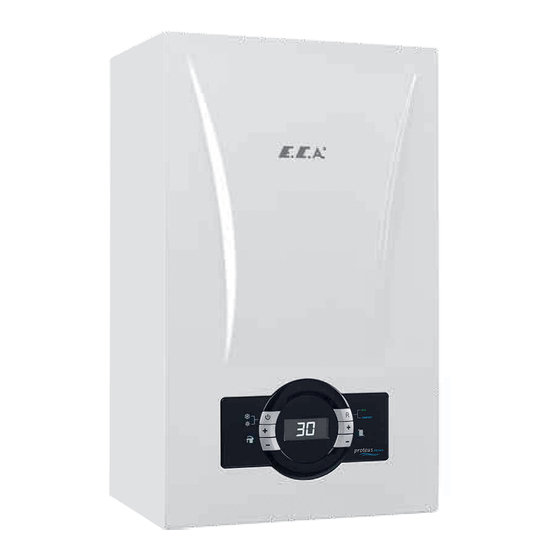
E.C.A. Proteus Premix 14 kW HM Installation And User's Operating Instructions
Condensing boiler
Hide thumbs
Also See for Proteus Premix 14 kW HM:
Table of Contents
Advertisement
Quick Links
Advertisement
Table of Contents

Subscribe to Our Youtube Channel
Related Manuals for E.C.A. Proteus Premix 14 kW HM


Summary of Contents for E.C.A. Proteus Premix 14 kW HM
- Page 1 14-20-24-28-30-35-42-45 HM/HCH/HST INSTALLATION AND USER'S OPERATING INSTRUCTIONS...
-
Page 3: Table Of Contents
INTRODUCTION 1- INTRODUCTION ........................... 4 2- GUARANTEE AND SERVICE ........................4 3- DEFINITIONS OF SYMBOLS ........................4 4- SAFETY RULES AND WARNINGS ......................5 5- PRODUCT .............................. 6 5.1- General Specifica�ons ........................6 5.2- Nota�ons of Product ........................7 5.3- Detailed View and List of Components ..................7 5.4- Electrical Drawing ........................ -
Page 4: 1- Introduction
1. INTRODUCTION First of all, we would like to thank you for choosing E.C.A brand. E.C.A. Proteus Premix condensing boilers have been designed for an efficient, safe and comfortable central heating and hot water requirement. The Proteus Premix condensing boilers can possibly use natural gas or LPG according to the desired fuel preference. -
Page 5: 4- Safety Rules And Warnings
4. SAFETY RULES AND WARNINGS 4.1. Safety Instructions When a gas leak is found or suspected; • Turn off the gas valve of the boiler and the valves of all other devices operating with gas. • Shut off the stove, oven and similar appliances to put their flame out. •... -
Page 6: 5- Product
CAUTION: The 2-amp bipolar fuse with a minimum contact opening of 3 mm must be used in the electrical connection of the boiler. 4.6. Usage and Maintenance • Read carefully instructions and precautions in this manual against wrong usage which causes unsafe conditions. -
Page 7: Nota�Ons Of Product
5.2. Notations of Product NOTATION DESCRIPTION Proteus Premix 14/20/24/28/30/35/42/45 kW HM Proteus Premix Hermetic Monotermic Condensing Boiler Proteus Premix 14/20/24/28/30/35/42/45 kW HCH Proteus Premix Hermetic Central Heating Condensing Boiler Proteus Premix 14/20/24/28/30/35/42/45 kW HST Proteus Premix Hermetic Storage Tank Condensing Boiler Table 1 5.3. - Page 8 5.3.1. HM Model CH Return DHW Return Supply Supply Figure 1.3 5.3.2. HCH Model CH Return CH Supply Figure 1.4 5.3.3. HST Model Storage Tank Supply CH Return CH Supply Storage Tank Storage Tank Return Figure 1.5...
- Page 9 5.4. Electrical Drawing Figure 2.1 Versiyon A...
-
Page 10: Electrical Drawing
Electrical Drawing FAN MOTOR R FAN MOTOR L POWER L. POWER N. PUMP NEUTR PUMP LINE 3WV CH 3WV DHW 3WV NEUTR Figure 2.2 Versiyon B... - Page 11 Electrical Drawing FAN MOTOR R FAN MOTOR L EARTH EARTH POWER L. POWER N. PUMP NEUTR PUMP LINE 3WV CH 3WV DHW 3WV NEUTR Figure 2.3 Versiyon C...
-
Page 12: 6- Boiler Packaging
6. BOILER PACKAGING CAUTION: Attention must be paid to warning on packaging regarding handling and storage. - The device is delivered in a cardboard box with dimensions of 735 x 345 x 490 (HxWxD) mm, supported by upper and lower styrofoam. (746 x 395 x 515 (HxWxD), valid for 42-45 kW.) Mounting bracket Figure 3 -Parts required for installation of the device (wall bracket, 5 gaskets for HM and HCH and 6 gaskets for... -
Page 13: 7- Flues
7. FLUES 7.1. Flue Sizes Flue gas connections between the boiler and the flue terminal must be made using original components specially designed for the condensing boiler to ensure that the device operates efficiently and correctly. Flue gas pipes and fittings of non-condensing boilers can not be used for exhausting gases from condensing boilers. -
Page 14: Distances For Placement Of Flues
7.3. Distances for Placement of Flues Figure 6 POSITION DISTANCE (cm) POSITION DISTANCE (cm) A-Below a windows G- Next to vertical or horizontal pipe H- Below the distance grille from B- Below an air vent the outside of the building I- Distance from the inner corner of C- Below rain channel the building... -
Page 15: 8- Installation
8. INSTALLATION 8.1. Selection of Installation Location of Device In addition to some restrictions given by TSE and authorized gas companies for the places where the device can be installed, the distances that must remain around the device for service, maintenance and use should be as shown in Figure 7. -
Page 16: Independent Opera�On From Ambient Air (Type C)
8.2. Independent Operation from Ambient Air (Type C) DANGER: The installation location of your condensing boiler and the flue gas connection must comply with the instructions specified by TSE authorized gas companies. DANGER: Unapproved combustion air / flue gas flow pipes may pose a risk of injury. Only use the manufacturer's original combustion air / flue gas flow pipes. -
Page 17: Connections
Figure 8 9. CONNECTIONS 9.1. Condensate Discharge Connection In condensing combi boilers, condensation occurs during combustion. The Informatıon amount of condensate varies depending on the operating conditions of the device. By consuming 1 m of natural gas, a maximum of 1.7 liters of condensate occurs. -
Page 18: Gas And Water Connec�Ons
9.2. Gas and Water Connections - Water and gas connections between the mounting bracket fixed on the wall and the boiler are mounted with the pipe group and nipple as shown in the figure. 9.2.1. HM Model a) CH flow ¾ ‘’ (hot) b) DHW outlet ½... -
Page 19: Electrical Connec�On
9.2.3. HST Model a) CH flow ¾ ‘’ (hot) b) Boiler supply water (hot) c) Gas inlet ¾’’ d) Boiler return (cold) e) Installation Filling Line ½ ‘’ f) CH return ¾’’ (cold) Figure 12 9.3. Electrical Connection Electrical installation should be made according to the national and local instructions. The boiler must be earthed and a standard 230 V AC –... -
Page 20: Room Thermostat
9.4. Room Thermostat One of the optional room thermostats compatible with your device can be used to control the heating of the space. E.C.A. Poly TOUCH Poly Plus 100 Wireless E.C.A. Poly COMFORT 400B Thermostat Room Thermostat 200B Thermostat 7006903006 7006903002 7006903007 E.C.A. -
Page 21: Outdoor Sensor
9.5. Outdoor Sensor To connect the room thermostat or outdoor sensor to the device, the connections behind the control panel are used. For the room thermostat, the bridged cable connection on the back of the control panel is removed and the outer air sensor is connected to free sockets on the terminal. It can be provided as an option according to boiler models. -
Page 22: Room Thermostat And Outer Air Sensor Connec�On
9.6. Room Thermostat and Outer Air Sensor Connection MAINBOARD MAINBOARD To make the room Solar system connection Timer cables are Boiler sensor cables are The outdoor air sensor thermostat connection, cables are connected to the connected to relevant connected to the is mounted by the bridge shown in the indicated terminal points. -
Page 23: 10- Commissioning, Use And Turning Off The Boiler
10. COMMISSIONING, USE AND TURNING OFF THE BOILER 10.1. Commissioning, Filling Water into Boiler and Heater Installation − First of all, the boiler electrical connection is made. The electrical connection of the device must be connected to a grounded socket line that can provide sufficient voltage (230 VAC 50 Hz) for the device. −... -
Page 24: 11- Control Panel
10.2. Using the Device 10.2.1. Switching off the Device You can switch off the boiler by holding down the ON/ OFF button for 3 seconds. LCD light will be OFF after 1 minute. Anti-freeze function remains active. 11. CONTROL PANEL 11.1. - Page 25 Domestic Hot Water Increase Temperature Button The temperature of the domestic water can be increased up to 65 °C thanks to the domestic water temperature increase button. Central Heating Water Increase Temperature Button Thanks to the heating circuit heating temperature increase button, the temperature of the heating water in the heating circuit can be increased up to 80°C.
- Page 26 11.3.2. Air Discharge Mode (AP Mode): It is the process that the device automatically performs to evacuate the air in the central heating installation for 160 seconds. During this mode, "AP" appears on the screen. The circulation pump runs for 15 seconds and stops for 5 seconds every 20 seconds.
-
Page 27: 12- Gas Conversion
12. GAS CONVERSION Gas conversion operation from LPG to natural gas or from natural gas to LPG should be performed by authorized service. If the user requests gas transformation after purchase of the device, it is subject to a fee. For the gas conversion process, a conversion kit is required. - Page 28 1- Press reset button. 2- If the error is still present (or persists) after reset, Flame circuit The electronic card notify authorized service of E.C.A. failure may be failed. 1- Change the electronic card. 2- If the error continues (or repeats) after the reset, E.C.A.
- Page 29 1- Press reset button. 2- If the error is still present (or persists) after reset, Ignition Circuit Error notify authorized service of E.C.A. 1- Press reset button. 2- If the error is still present (or persists) after reset, notify authorized service of E.C.A. 1- Press reset button.
-
Page 30: 14- Usefull Information On Product
1- Press reset button. Flue Gas Lock Up at Mainboard may be 2- If the error is still present (or persists) after reset, High Temperature defective. notify authorized service of E.C.A. 1- The fan cable is not plugged in or there may be a loose connection. -
Page 31: 15- Annexes
15. ANNEXES 15.1. Characteristic curve of water pressure height of the pump (pump head-flow rate) 15-60 (for 14-20-24-28-30 kW models) Flow - Head Curve 7,00 6,00 5,00 4,00 3,00 2,00 1,00 0,00 0,00 0,50 1,00 1,50 2,00 2,50 Q [m3/h] 15-70 (35-42-45 kW) Flow - Head Curve 8,00... -
Page 32: 16- Installation Template
16. INSTALLATION TEMPLATE 16.1. HM Model ıo 160mm 160mm (]() - Page 33 16.2. HCH Model 160 mm 160 mm...
- Page 34 16.3. HST Model ıo 160 mm 160 mm...
-
Page 35: Technical Specifications Table
17. ERP GUIDE 17.1. Technical Specifications Table PROTEUS PROTEUS PROTEUS PROTEUS PROTEUS PROTEUS PROTEUS PROTEUS PREMIX 14 PREMIX 20 PREMIX 24 PREMIX 28 PREMIX 30 PREMIX 35 PREMIX 42 PREMIX 45 Product Type Unit HM-HCH- HM-HCH- HM-HCH- HM-HCH- HM-HCH- HM-HCH- HM-HCH- HM-HCH- Gas Category I2H, I3P, I2Esi, I2E(S), II2L3P, II2H3P, II2ELL3P, II2Esi3P Flue Type... -
Page 36: Ce Marking
17.2. CE Marking The CE mark certifies that the products meet the essential requirements of the applicable regulations in line with the declaration of conformity. The manufacturer can be consulted for a declaration of conformity. 17.3. Product Information Sheet (ErP) The product data presented below complies with the requirements of EU regulations 811/2013 and 813/2013 to supplement directives 92/42/EU and 92/42/EEC. -
Page 37: Package Information Card Stating The Central Heating Energy Efficiency Of The Package
17.4. Package information card stating the central heating energy efficiency of the package 17.4.1. Package Information - Combi Boiler “I” Seasonal Space Heating Energy Efficiency of the Combi Boiler (Table 7) “I”: The value of the seasonal heating efficiency of the primary central heater, expressed in %. Temperature Controller Class I = 1%, Class II = 2%, Class III = 1.5%, (Room Thermostat-Outdoor Air Sensor) - Page 38 Water Heating Energy Efficiency of Combination Heater (Table 8) “I” Declared load profile: Solar Energy Device Contribution Auxiliary Electric From the solar energy device data sheet ( 1.1 x 'I' - 10 % ) x 'II' - 'III' - 'I' = Water Heating Energy Efficiency of the Package under Average Climatic Conditions Water Heating Energy Efficiency Class of the Package under Average Climatic Conditions Water Heating Energy Efficiency of the Package under Average Climate Conditions...
-
Page 39: 18- Removal Information
18. REMOVAL INFORMATION 18.1. Unpacking the New Device Packaging protects your device against transport damage. All materials used in packaging are environmentally friendly and can be reused. Please help: Dispose of the packaging in a way that will not harm the environment. To obtain information about current troubleshooting methods and methods, please contact your authorized dealer or your municipality. - Page 40 PRODUCTION PRODUCTION EMAS MAKINA SANAYI A.S Organize Sanayi Bölgesi 3. Kısım Organize Sanayi Bölgesi 3. Kısım Mustafa Kemal Bulvarı No: 13 45030 MANİSA / TÜRKİYE Tel: +90 236 213 00 21 Fax : +90 236 213 08 59 email: emas@emas.com.tr www.emas.com.tr...
Need help?
Do you have a question about the Proteus Premix 14 kW HM and is the answer not in the manual?
Questions and answers