
Related Manuals for E.C.A. ARCEUS EC 6 kW MT


Summary of Contents for E.C.A. ARCEUS EC 6 kW MT
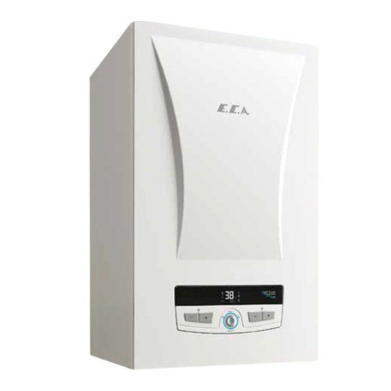
- Page 1 ARCEUS ELECTRIC COMBI BOILER ARCEUS EC 6-9-12-15-18-24-27 kW MT / CH / ST SERVICE MANUAL...
-
Page 2: Table Of Contents
TABLE OF CONTENTS GENERAL WARNINGS ....................4 1. Device Control, Button Functions and Service Menus ........5 1.1. Control Panel ..........................5 1.2. Button Functions ........................5 1.3. Introduction to Parameter, Information and Error History Menus ..........6 1.4. Cable Diagrams by Capacities ....................9 1.5. - Page 3 4. PART DEFINITIONS AND ERROR TYPES ............30 4.1. Heating Resistor ........................30 4.2. Main Exchanger Tank ......................32 4.3. Circuit Breaker ......................... 33 4.4. Neutral Busbar ......................... 34 4.5. Mainboard ..........................34 4.6. Relay Board ..........................35 4.7. Pump ............................37 4.8.
-
Page 4: General Warnings
GENERAL WARNINGS - Circuit Breaker poles, contactor main and auxiliary contacts and coil terminals, motorised valve connector terminals, resistance and relay contact terminals, pump connector terminals, overheat thermostat and motherboard should never be contacted with bare hands during interventions to the device. - If water leaks are observed in the cabinet during the intervention to the device, the energy supply should be cut off immediately and supplied in a controlled manner after the wet areas are dried. -
Page 5: Device Control, Button Functions And Service Menus
1. Device Control, Button Functions and Service Menus 1.1. Control Panel The control panel that provides control of the device consists of 5 different buttons. The layout of the buttons is as follows: 1.2. Button Functions Key Number Key Name Function - The short press switches between STANDBY MODE, SUMMER MODE and WINTER MODE. -
Page 6: Introduction To Parameter, Information And Error History Menus
1.3. Introduction to Parameter, Information and Error History Menus The service menu is accessed if K1 key is pressed for 5 seconds. The sub-menu desired to be entered is opened with K1 key by switching between the symbols displayed on the screen with the K5 and K6 keys. - Page 7 Pump overrun time after central heating request (sec) 0-99 K factor for outdoor temperature sensor compensation 0-30 Domestic water shut off temperature configuration 0: Stop at 71°C 1: Domestic water set value + FP04 Boiler Capacity 6,9,12,15, 6 = 6KW 18,24,27 9=9KW 12 = 12KW...
- Page 8 Information Number Description Instant central heating inlet temperature (°C) Instant central heating return temperature (°C) Instant domestic water temperature (Instantaneous/Tank/Above tank) (°C) Instant domestic water temperature (Below tank) (°C) Solar panel temperature (°C) Instant flow (L/minute x 10) Instant outdoor air temperature (°C) Calculated central heating set temperature (°C) Number of active relays Software version...
-
Page 9: Cable Diagrams By Capacities
1.4. Cable Diagrams by Capacities 1.4.1. 6-9 kW Connection Diagram Circuit Breaker Contactor Electrical Heaters Relay Boards CH Inlet NTC CH Return NTC Boiler Tank NTC 3-Way Valve DHW Solar STB Water Pressure Sensor DHW Supply Sensor Modbus Haberleşmesi Pump... - Page 10 1.4.2.12-15 kW Connection Diagram Circuit Breaker Contactor Electrical Heaters Relay Boards CH Inlet NTC CH Return NTC DHW/Boiler Tank NTC 3-Way Valve DHW Solar STB Water Pressure Sensor DHW Supply Sensor Modbus Communication Pump...
- Page 11 1.4.3.18-24 kW Connection Diagram Circuit Breaker Contactor Electrical Heaters Relay Boards CH Inlet NTC CH Return NTC DHW/Boiler Tank NTC 3-Way Valve DHW Solar STB Water Pressure Sensor DHW Supply Sensor Modbus Communication Pump...
- Page 12 1.4.3. 27 kW Connection Diagram Circuit Breaker Contactor Contactor Electrical Heaters Electrical Heaters Relay Boards CH Inlet NTC CH Return NTC DHW/Boiler Tank NTC 3-Way Valve DHW Solar STB Water Pressure Sensor DHW Supply Sensor Modbus Communication Pump...
-
Page 13: Detailed View And List Of Components
1.5. Detailed View and List of Components Air Purge Expansion Vessel Circuit Breaker Drain Valve Ground Terminal Block Plate Heat Exchanger Neutral Terminal Block Circulation Pump Neutral Busbar Relay Boards Cantactor Pressure Sensor 3 Way Valve Immersion type NTC 3 Bar Safety Valve Flow sensor Electric Heaters Overheat thermostat... -
Page 14: Power Supply Connection Requirements
1.6.Power Supply Connection Requirements Supply Cord Nominal Supply Line Minimum Device Power Supply Current (A) Circuit Breaker Capacity Single-phase B32-1P ARCEUS 6 CH-ST Three-phase 5x2.5 B10-3P Single-phase 3x10 B40-1P ARCEUS 9 CH-ST Three-phase 5x2.5 B15-3P Single-phase 3x10 B63-1P ARCEUS 12 MT-CH-ST Three-phase B20-3P... -
Page 15: Error Codes And Solutions
2. Error Codes and Solutions 2.1. Solutions for Coded Errors ERROR ERROR DESCRIPTION TYPE SOLUTION CODE TYPE 1- Reset the error. Limit Thermostat This error is received, if one of LOCKOUT 2- Measure between the terminals of the overheat Protection Error the central heating inlet or return temperature sensors reads over thermostat. - Page 16 Central Heating This error is received if the 1- Make sure that the cables of the NTC in the supply ERROR Inlet central heating inlet line are connected. Temperature temperature sensor is short- 2- If the cables are plugged in, check the cables end- Sensor Error circuit, open-circuit, or to-end.
-
Page 17: Solutions For Errors Not Being Displayed
2.2. Solutions for Functional Faults of Device 2.2.1. In case the heater circuit of the device underheats or does not heat at all: 1- Put the device into test mode by pressing and holding K3 and K5 together for 5 seconds. When the device is put into test mode, "FT"... - Page 18 d- If there is no loose contact in the cables and the resistance of the resistors are within normal values, take measurements from other resistors in the same group. If all the resistors in a single resistor group are dead, check that the relay trigger cables are undamaged and connected to both the mainboard and relay board sides.
- Page 19 2.2.2. In case the device underheats or does not heat domestic water at all: 1- Put the device into test mode by pressing and holding K3 and K5 together for 6 seconds. When the device is put into test mode, "FT" will be displayed on the screen. In this case, measure the current through the resistor neutral cables using a clamp meter and detect whether there is a dead resistor.
- Page 20 e- If the connections are correct, disconnect the power of the device from the Circuit Breaker, disconnect the dead resistor cables from the relay boards and unplug them, and turn on the Circuit Breaker again and put the device into test mode with K3 and K5. While the device is in test mode, measure the resistance between the pins you disconnected.
-
Page 21: Assemblying/Disassemblying Procedures Of Parts
If the glass Circuit Breaker is lit, measure the resistance between the phase and neutral terminals of the pump, motorised valve, terminals A1 and A2 of the contactor coil, A1 and A2 terminals of the relays on the board to detect the part that may caused the short-circuit and replace it. -
Page 22: Circuit Breaker
3.4. Circuit Breaker Pull the flanges under the circuit breaker down with the help of a screwdriver so that they can be removed from the rail. When installing the Circuit Breaker to the rail, you can first insert the tabs of the upper part of the Circuit Breaker into the rail and then push the lower part towards the rail. -
Page 23: Mainboard
3.10. Mainboard The mainboard can be disassembled by removing the screws and connectors at the 4 corners of the mainboard. Suitable Hand Tool: Cross-screwdriver Suitable Tightening Torque: 0.5±0.1 Nm E.C.A. ARCEUS ELECTRIC COMBI MAINBOARD PARAMETER ADAPTATION The mainboard is defined as a single spare part code for all capacities and configurations (Spare Part Code: 7006250015). - Page 24 Adjusting Boiler Capacity While the device is on the normal operation screen, the service menu is accessed by pressing the mode selection button (K1) for 5 seconds. When "tS" symbol is displayed on the screen, press K1 once again to access the password entry screen.
- Page 25 When "tS" symbol is displayed on the screen, press K1 once again to access the password entry screen. The number 03 is selected with the heater water temperature adjustment buttons and the password is confirmed with one of the domestic water adjustment buttons (K5 or K6). The values "P" and "00" will blink alternately on the screen.
-
Page 26: Relay Boards
3.11. Relay Boards Relay boards can be disassembled by removing 3 screws and contact connections. Suitable Hand Tool: Cross-screwdriver 3.12. Expansion Tank - For removing the holdfast: Suitable Hand Tool: Cordless screwdriver - For removing the flex hose: Suitable Hand Tool: AA 18 Wrench 3.13. -
Page 27: Motorised Valve
3.17. Motorised Valve You can disassemble the motorised valve by removing its clip. 3.18. Submersion Type NTC You can disassemble the submersion type NTC by removing its clip. 3.19. Plate Exchanger After removing the manifold connections of the plate exchanger with a size 4 hex key, you can push the exchanger back and remove it from the lower service cover. -
Page 28: Resistor Replacement
3.23. Resistor Replacement If one of the resistors is short- or open-circuited, the cables are deformed or another physical deformation occurs, the resistor may be replaced without removing the exchanger tank. For tank replacement, drain the water inside the tank with the drain valve, and loosen the resistor flange. Afterwards, disassembly the resistor to be replaced by removing the lower or upper service panel depending on whether the resistor is at the bottom or the top of the tank, install the new one into the same place of the device, and tighten the flange. - Page 29 Making Controller Connections MAINBOARD MAINBOARD DETAIL B DETAIL A Timer cable connections are Boiler sensor cable connections The solar system connection The outdoor air sensors In order to connect the room connected to the corresponding are connected to the cables are connected to the cables are installed by thermostat, the bridge seen terminal points.
-
Page 30: Part Definitions And Error Types
4. PART DEFINITIONS AND ERROR TYPES 4.1. Heating Resistor Subject Description Function of Part It gives the electrical power burned on it to the tank as heat and provides heating of the water in the exchanger body. Impact in Case of Malfunction; 1- The Circuit Breaker blows. - Page 31 Test definition Test Method Resistance measurement Resistance between each phase input terminal of the resistor and the neutral busbar or terminal is measured. This value should be in the range of 24-28 for 6 kW resistor groups, and 16-19 for 9 kW resistor groups.
-
Page 32: Main Exchanger Tank
4.2. Main Exchanger Tank Subject Description It provides a heat exchange environment between Function of Part the resistors mounted on it and the installation water. In case of water leakage, it may cause pressure drop in Impact in Case of Malfunction the plumbing and short-circuits in the device. -
Page 33: Circuit Breaker
4.3. Circuit Breaker Subject Description It prevents the device and installation from being damaged by Function of Part switching the circuit off in case of over-current. 1- It blows when there is no over-current. Impact in Case of Malfunction 2- The power supply of the device is switched off incorrectly. Main Associated Error Codes Visual inspection, observation when operating at full Diagnostics and Test Method... -
Page 34: Neutral Busbar
4.4. Neutral Busbar Subject Description Function of Part It is a common connection point that provides the distribution of the neutral line entering from the neutral terminal on the device. Impact in Case of Malfunction The neutral line may not reach the resistors or the mainboard. -
Page 35: Relay Board
4.6. Relay Board Subject Description Function of Part Commissioning the resistors by making the last stage switching and meeting the heating request. Impact in Case of Malfunction 1- The device does not heat or heats below its capacity. 2- If it is stuck in the transmission, it can heat even though there is no heating request, and if there is no water circulation, it may cause an overheating error. - Page 36 Voltage measurement over the Put the device in test mode. When fT is displayed on the screen, disconnect the cable relay board cables and measure the voltage. Touch the probe coming out of the port of the measurement tool to the cable entering the terminal no. 4 of the relay board, and touch the other end of the probe cable coming out of the common (COM) port and the other three cables.
-
Page 37: Pump
4.7. Pump Subject Description Function of Part It pressurises the water in the closed-circuit installation and provides water circulation. In addition, it ensures the removal of air in the installation with water circulation. 1- The boiler gives overheating error. Impact in Case of Malfunction 2- Heated water does not transmitted to the installation. -
Page 38: Neutral And Ground Terminals
4.8. Neutral and Ground Terminals Subject Description Function of Part It provides the transmission and distribution of the neutral and grounding lines entering from the main supply of the device to the device. Impact in Case of Malfunction Neutral and grounding lines in the electrical installation do not have access to the device. - Page 39 Test definition Test Method Voltage and Position While the device is connected to the power, the motorised Control in Central Heating valve cable is removed and the device is put into central heating mode. Resistance between terminals no. 1-2 is measured.
-
Page 40: Plate Exchanger
4.10. Plate Exchanger Subject Description Function of Part It enables the water heated in the main exchanger to transfer heat to the domestic water during domestic water heating. Impact in Case of Malfunction The domestic water and the central heating water may mix. The water pressure in the installation may drop. -
Page 41: Contactor
4.11. Contactor Subject Description Function of Part It ensures the continuity of the power circuit by transmitting the energy coming from the Circuit Breaker output contacts of the device to the relays. It protects the device and the installation by turning on the power circuit in fault situations where the heating must be turned off. - Page 42 Main Contact Conduction Control While the contactor is unplugged, check whether there is energy at the contact outputs no. 2, 4 and 6. Each of the contacts must have energy. Then switch the device to "OFF" mode with K1, deactivate the contactor and take the same measurement. None of the contacts must have energy.
-
Page 43: Expansion Tank
4.12. Expansion Tank Subject Description Function of Part It ensures that the system pressure does not increase in case the water in the closed-circuit water installation expands by heating. Impact in Case of Malfunction Main Associated Error Codes Diagnostics and Test Method Expansion tank gas pressure measure Maintenance Requirement There is no special maintenance requirement. -
Page 44: Limit Thermostat
4.13. Overheat thermostat Subject Description Function of Part It provides protection by shutting off the contact in case of overheating in the main exchanger. Impact in Case of Malfunction 1. Although there is overheating on the upper surface of the heat exchanger, it may not turn on the contact and protect it. -
Page 45: Surface Type Ntc
4.14. Surface Type NTC Subject Description Function of Part It ensures that the device works in accordance with its function, by measuring the central heating supply and return water temperatures. Impact in Case of Malfunction It causes the central heating not to work properly, not to heat up or to overheat more than the set temperature. -
Page 46: Submersion Type Ntc
4.15. Submersion Type NTC Subject Description Function of Part It is the element that measures the temperature of the water taken from the domestic water outlet. Impact in Case of Malfunction 1- The desired set temperature cannot be achieved and user comfort is disturbed. 2- The device will not work. -
Page 47: Flow Sensor
4.16. Flow Sensor Subject Description Function of Part It is the element that detects the request when the flow starts in the domestic water installation. Impact in Case of Malfunction 1- The domestic water request cannot be detected and heating does not occur. -
Page 48: Air Purger
4.17. Air Purger Subject Description Function of Part It allows the air remained in the installation circuit to be discharged. Impact in Case of Malfunction In case of faulty operation, it discharges water instead of air. It causes the water pressure in the installation to drop. -
Page 49: Water Pressure Sensor
4.18. Water Pressure Sensor Subject Description Function of Part It prevents dry combustion in the device by measuring the water pressure in the installation. Impact in Case of Malfunction 1- Device gives low or high pressure error. 2- A value different from the actual water pressure is displayed on the user screen. -
Page 50: Flow Turbine
4.19. Flow Turbine Subject Description Function of Part When there is a domestic water request, the turbine structure it has starts to turn and creates the magnetic field that the flow sensor will detect. Impact in Case of Malfunction The device cannot detect the domestic water request, it continues to make central heating even if there is a domestic water request. -
Page 51: Bar Safety Valve
4.20. 3 Bar Safety Valve Subject Description Function of Part It reduces the pressure in the installation by discharging the water at the installation water pressure above 3±0.3 bar. Impact in Case of Malfunction 1- It may leak water at low pressures, causing the installation pressure to drop.
Need help?
Do you have a question about the ARCEUS EC 6 kW MT and is the answer not in the manual?
Questions and answers
Хочу на лето отключить принудительно 2 Тены что бы меньше мотало электричество
To manually disable 2 heating elements on the E.C.A. ARCEUS EC 6 kW MT device to reduce electricity consumption, disconnect the cables of the desired heating elements from the relay boards. Then, unplug those cables to ensure they do not receive power. Make sure to switch off the circuit breaker before disconnecting any cables, and turn it on again after completing the disconnection.
This answer is automatically generated