
Related Manuals for E.C.A. Proteus Premix Series


Summary of Contents for E.C.A. Proteus Premix Series
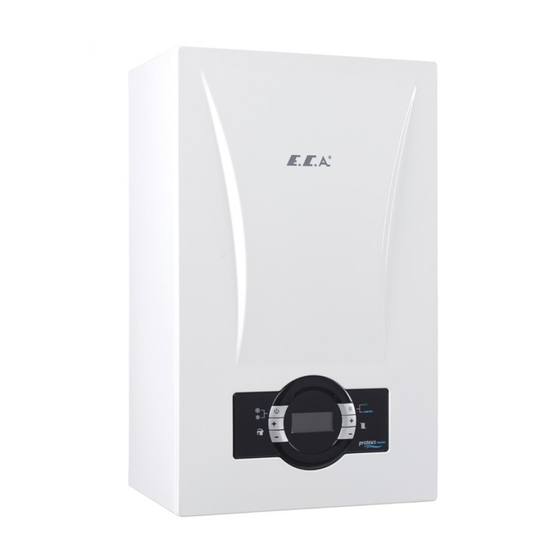
- Page 1 PROTEUS PREMIX CONDENSING BOILER PROTEUS PREMIX PPR 14/20/24/28/30/35 HM/HCH/HST INSTALLATION AND USER'S OPERATING INSTRUCTIONS...
-
Page 2: Table Of Contents
INTRODUCTION 1 - INTRODUCTION ..........................3 2- GUARANTEE AND SERVICE ........................3 3- DEFINITIONS OF SYMBOLS ........................3 4- SAFETY RULES AND WARNINGS ......................4 5- PRODUCT ............................. 5 5.1- General Specifications ........................5 5.2- Notations of Product ........................5 5.3- Detailed View and List of Components .................. -
Page 3: Introduction
1 – INTRODUCTION First of all, we would like to thank you for choosing E.C.A brand. E.C.A. Proteus Premix condensing boilers have been designed for an efficient, safe and comfortable central heating and hot water requirement. The Proteus Premix condensing boilers can possibly use natural gas or LPG according to the desired fuel preference. -
Page 4: 4- Safety Rules And Warnings
4- SAFETY RULES AND WARNINGS 4.1- Safety Instructions When a gas leak is found or suspected; • Turn off the gas valve of the boiler and the valves of all other devices operating with gas. • Shut off the stove, oven and similar appliances to put their flame out. •... -
Page 5: 5- Product
4.6 - Usage and Maintenance • Read carefully instructions and precautions in this manual against wrong usage which causes unsafe conditions. • The boiler should be checked and serviced for general maintenance once a year. Maintenance and service operations must be carried out only qualified person. •... -
Page 6: Detailed View And List Of Components
5.3- Detailed View and List of Components 5.3.1- HM Model 1- Main Exchanger 2- Silencer 3- Venturi 4- Fan 5- Motorized Valve 6- Condensing Water Hose 7- Outlet Manifold 8- 3 Bar Safety Valve 9- Pressure Sensor 10- Siphon 11- Plated Heat Exchanger 12- Gas Valve 13- Return Manifold 14- Pump... - Page 7 5.3.2- HST Model 1- Main Exchanger 2- Silencer 3- Venturi 4- Fan 5- 3 Way Valve 6- Condensing Water Hose 7- Outlet Manifold 8- 3 Bar Safety Valve 9- Pressure Sensor 10- Siphon 11- Gas Valve 12- Return Manifold 13- Pump 14- Flexible Connection Hose 15- Expansion Tank (8 liters) 16- Expansion Tank Holder Bracket...
- Page 8 5.3.3- HCH Model 1- Main Exchanger 2- Silencer 3- Venturi 4- Fan 5- Flue Gas Sensor 6- Condensing Water Hose 7- Outlet Manifold 8- 3 Bar Safety Valve 9- Pressure Sensor 10- Siphon 11- Gas Valve 12- Return Manifold 13- Pump 14- Flexible Connection Hose 15- Expension Vessel(8L) 16- Rainwater Hose...
-
Page 9: Technical Specifications
5.4- Technical Specifications... - Page 11 *Only HM *Boiler sensor in Model HST model * Except of HCH Model...
-
Page 12: Boiler Packaging
6. BOILER PACKAGING CAUTION: Attention must be paid to warning on packaging regarding handling and storage. - The device is delivered with a cartonboard with dimensions of 735 x 345 x 490 (HxWxD) mm, supported by upper and lower styrofoams. Mounting bracket Figure 5 - Parts required for installation of the device (wall bracket, 5 gaskets for HM and HCH and 6 gaskets for HST... -
Page 13: Flues
1. 90° C Elbow 6. Flange Screws 2. Exhaust Gas Tap 7. Flange Gaskets 3. Air Inlet Tap 8. Flue Exhaust Terminal 4. Sealing Gasket Ø60 or Ø80 9. Inner Wall Connection Flange 5. Sealing Gasket Ø 100 or Ø125 10. -
Page 14: Distances For Placement Of Flues
7.3- Distances for Placement of Flues Figure 8 POSITION DISTANCE (cm) POSITION DISTANCE (cm) A-Below a windows G- Next to vertical or horizontal pipe H- Below the distance grille from the outside B- Below an air vent of the building C- Below rain channel I- Distance from the inner corner of the building... -
Page 15: 8- Installation
8- INSTALLATION 8.1- Selection of Installation Location of Device The boiler must be installed in accordance with gas safety regulations and relevant standards. Additionally, the clearance around the boiler should be as shown in fig 4. In order to make service, maintenance and usage easier. -
Page 16: Independent Operation From Ambient Air (Type C)
8.2- Independent Operation from Ambient Air (Type C) DANGER: For room sealed operation, the boiler location and air/flue terminal position must obey national and local requirements, gas safety regulations and relevant standards. -Type C (hermetic) devices are not suitable for outdoor installations. These devices should be installed inside the building. -
Page 17: Connections
Figure 10 9 - CONNECTIONS 9.1- Condensate Discharge Connection • All condensing boilers generate condensing discharge. The amount of the condensate water depends on the working conditions of your appliance. This can be up to 1.7 litres condensate water an hour. •... -
Page 18: Gas And Water Connections
9.2- Gas and Water Connections 9.2.1- HM Model - Water and gas supply connections between the boiler and the mounting bracket can be fixed with the optional pipes and the nipples as shown in Figure 12. a) CH flow ¾ ‘’ (hot) b) DHW outlet ½... -
Page 19: Electrical Connection
9.2.2- HST Model a) CH flow ¾ ‘’ (hot) b) Boiler supply water (hot) c) Gas inlet ¾’’ d) Boiler return (cold) e) Installation Filling Line ½ ‘’ f) CH return ¾’’ (cold) Figure 14 9.3- Electrical Connection Electrical installation should be made according to the national and local instructions. The boiler must be earthed and a standard 230 V AC –... -
Page 20: Room Thermostat
9.4- Room Thermostat Optional room thermostats compatible with your device can be used to control heating system. E.C.A. On/Off Room E.C.A. Smart Room E.C.A. Digital Room Modulated, Thermostat Thermostat Programmable T6360 T6360 LAGO FB OT 7006901312 7006907531 7006902518 E.C.A. Digital Room Thermostat E.C.A. -
Page 21: Outdoor Sensor
9.5- Outdoor Sensor To connect the room thermostat or outdoor sensor to the device, the connections behind the control panel are used. For the room thermostat, the bridged cable connection on the back of the control panel is removed and the outer air sensor is connected to free sockets on the terminal. -
Page 22: Room Thermostat And Outer Air Sensor Connection
9.6- Room Thermostat and Outer Air Sensor Connection MAINBOARD MAINBOARD DETA IL B DET AIL A To make the room thermostat Outdoor sensor is installed Timer cables are Boiler sensor cables connected Solar system connection cables are connection, the bridge shown in by connecting its cables to to relevant terminal points. -
Page 23: 10- Commissioning, Use And Turning Off The Boiler
The connections of room thermostat, outdoor sensor and timer must be performed certainly by qualified person. 10- COMMISSIONING, USE AND TURNING OFF THE BOILER 10.1- Commissioning, Filling Water into Boiler and Heater Installation - First of all, the electrical connection of the boiler is done. The electrical connection of the device must be connected to a grounded power supply line that can supply enough voltage (230 VAC, 50 Hz) for the device. -
Page 24: 11-Control Panel
10.2- Using the Device 10.2.1- Switching off the Device You can switch off the boiler by holding down the ON/ OFF button for 3 seconds. LCD light will be OFF after 1 minute. Anti-freeze function remains active. 11-CONTROL PANEL 11.1- Functions of Buttons The control panel consists of the relevant elements as shown in figure 17 below. - Page 25 back to normal operation state. As for a blocking error, the fault cannot be removed from the LCD display pressing the "Reset" button (FXX). When this error is corrected, error code is automatically disappears from LCD screen. The first time the device starts, it will start working in Comfort mode. Once the Reset button is pressed when operating in Comfort mode, the device will switch to Eco mode.
- Page 26 button no. 1 (position selector) pressed for 3 seconds continuously. When -OFF- is displayed on screen, mode is activated. 11.3.2- Air Discharge Mode (AP Mode): It is the process that the device automatically activates to discharge air in the central heating installation for 160 seconds. In this mode, "AP" is displayed on the screen. The circulation pump runs for 15 seconds an then stops every 5 seconds in intervals of every 20 seconds.
-
Page 27: 12- Gas Conversion
• If device will not be operated for a while in places where there is risk of freezing, then it is necessary to drain the water or to use an anti-freeze agent. 12 – GAS CONVERSION Gas conversion operation from LPG to natural gas or from natural gas to LPG should be performed by authorized service. - Page 29 Table 4...
-
Page 30: 14- Usefull Information On Product
14- USEFULL INFORMATION ON PRODUCT 14.1- Information on the Efficient Use of the Combi Boiler in Terms of Safety and Energy Consumption Isolation of your building is extremely important. Energy saving is achieved at a considerable degree since the heat loss is lowest in houses with double-glazed windows and insulated walls. •... -
Page 31: 15- Annexes
14.4.2- GUARANTEE STARS You can get warranty of 1 to 3 years for your safely used E.C.A boilers, of which guarantee period expires. Thanks to guarantee stars and through additional warranty, your device with expired guarantee can be provided with maintenance up to 3 years without charging for spare parts, labor and service charges. - Page 32 16- INSTALLATION TEMPLATE 16.1 HM Model...
- Page 33 16.2 HCH Model L!') L!') ..C") 160 mm 160 mm • + cJiD ®...
- Page 34 16.2 HST Model L!') L!') ..C") 160 mm 160 mm • •...
- Page 35 1. PRODUCT FICHES Product fiche for combination boilers as required by EU regulations No 811/2013...
- Page 40 DECLERATION OF CONFORMITY 0085-DVGW CERT GmbH PROTEUS PREMIX 14-20-24-28-30-35 HM/HCH/HST DG PROTEUS PREMIX 14-20-24-28-30-35 HM/HCH/HST LPG 2009/142/AT Gaz Yakan Cihazlar Direktifi / Gas Aplliances Directive 2009/142/EC EN 15502-1 2016/426 GAR Gaz Yakan Cihazlar Regülasyonu / EU Regulation on Appliances Burning Gaseous Fuels: EU/2016/426, EN 15502-2-1 Belirli Gerilim Sınırları...
- Page 42 SALES PRODUCTION EMAS MAKİNA SANAYİ A.Ş. EMAS MAKİNA SANAYİ A.Ş. Yalı Mah. Ziya Gökalp Cd. No:3 34844 Organize Sanayi Bölgesi 3. Kısım Maltepe / İSTANBUL Mustafa Kemal Bulvarı No: 13 Phone : +90 216 442 34 41 45030 MANİSA Fax : +90 216 442 39 96 Phone : +90 236 213 00 21 email: satis@emas.com.tr Fax : +90 236 213 08 59...
Need help?
Do you have a question about the Proteus Premix Series and is the answer not in the manual?
Questions and answers