Advertisement
Quick Links
Advertisement

Subscribe to Our Youtube Channel
Summary of Contents for Phono Solar PowerHub 1800
- Page 1 Solar Generator Installation Guide www.phonosolarusa .com...
- Page 2 Contents 1 Important Safety Instructions 2 Introduction 3 Planning 4 Installation...
- Page 3 A Specifications...
-
Page 4: About This Guide
About This Guide About This Guide Purpose Scope Audience Organization... - Page 5 About This Guide Conventions Used WARNING CAUTION Important: Abbreviations and Acronyms Abbreviation or Acronym Definition Related Information...
-
Page 6: Important Safety Instructions
About This Guide Important Safety Instructions WARNING General Precautions Precaution for Solar anel... - Page 7 About This Guide ² º...
- Page 8 About This Guide Precaution for PowerHub 1800 WARNING: Limitations on use WARNING (Operator's Guide)
- Page 9 About This Guide Basic Safety...
- Page 10 • Consult the dealer or an experienced radio/TV technician for help. Power Down Procedure If softwired..To Power Down the PowerHub 1800: Press ON/OFF Switch to turn OFF Inverter/Charger Disconnect Loads Disconnect the Battery Box(es)
- Page 11 About This Guide If hardwired..To Power Down the PowerHub 1800: WARNING: Shock Hazard If no DC disconnect is used, then the DC input sources (solar or wind) will have to be physically disconnected to ensure power is OFF. Disconnect Loads connected to...
- Page 12 Introduction Chapter 2 describes the features and functions of the Solar Generator. The PowerHub 1800...
- Page 13 Introduction Features and Functions...
- Page 14 Introduction...
- Page 15 Introduction Inverter The inverter consists of the following user features: Features • Inverter Control Panel • Four 120 Vac outlets on the front panel. • One supplementary protector to protect the 120 Vac outlets from overload. • Two Battery Box Connection Ports (one on each side) Input/Output terminals are located under top panel.
- Page 16 Introduction Grounding The inverter has two AC Ground terminals and one equipment ground terminal. In addition, there are ground fault protection terminals for solar and wind renewable energy inputs (a 32 A and an 80 A). See Figure on page for a detailed illustration of the Input/Output and ground terminals.
- Page 17 Introduction Applications The Solar Generator could be a home backup power, an emergency power or a small/home office backup power. Important: Installations of this kind must be certified/approved as “code-compliant” to the national and local building and electrical codes. Installers should have adequate knowledge of national and local code to ensure the installation passes inspection by the local electric authority.
- Page 18 Introduction Applications Important: Installations of this kind must be certified/approved as “code-compliant” to the national and local building and electrical codes. Installers should have adequate knowledge of national and local code to ensure the installation passes inspection by the local electric authority. Example only.
- Page 19 Introduction Applications Important: Installations of this kind must be certified/approved as “code-compliant” to the national and local building and electrical codes. Installers should have adequate knowledge of national and local code to ensure the installation passes inspection by the local electric authority. Example only.
- Page 20 Introduction Hardwired Permanent Applications Utility Backup Applications Important: Installations of this kind must be certified/approved as “code-compliant” to the national and local building and electrical codes. Installers should have adequate knowledge of national and local code to ensure the installation passes inspection by the local electric authority. Example only.
- Page 21 Introduction Wind Applications Important: Installations of this kind must be certified/approved as “code-compliant” to the national and local building and electrical codes. Installers should have adequate knowledge of national and local code to ensure the installation passes inspection by the local electric authority. Maximum size of wind turbine: •...
- Page 22 Introduction Combination Applications The PowerHub 1800 can be used for the other entry-level applications as well. Important: Installations of this kind must be certified/approved as “code-compliant” to the national and local building and electrical codes. Installers should have adequate knowledge of national and local code to ensure the installation passes inspection by the local electric authority.
- Page 23 The PowerHub 1800 can be used for the following entry-level applications. Softwired Generator Applications (Plug-and-go) The PowerHub 1800 comes assembled with an AC input cord. This AC cord can be plugged into a 120 Vac outlet on a generator to charge the batteries.
- Page 24 Planning...
- Page 25 Planning Planning Overview Important: This unit is intended as an entry-level inverter/charger backup system. To use it as a stand-alone power source, it is not required to do any special installation procedures. However, if your installation involves renewable energy (solar or wind generators) or requires hardwiring for any reason, if you do not have adequate knowledge of national and local building and electrical codes, do not attempt to...
-
Page 26: Tools Required
Planning Tools Required The following tools may be required for installing this equipment: ❐ #2 Phillips screwdriver(s) ❐ Slotted screwdriver(s) ❐ Wire strippers ❐ Torque wrench ❐ Socket wrench and sockets (½ in. for the wind DC input terminal, and 10 mm for the solar DC input terminal) ❐... - Page 27 Planning Sunlight Choose an appropriate location that provides the most direct sunlight and can support the solar panel, and is free from shade. Be aware of surrounding objects which may obscure the sun from the panel. This solar panel is weatherproof including UV protection and protecting from rain, snow, storm and anyzweather effects of -35 o F–...
- Page 28 Planning Batteries Important: The PowerHub 1800 is designed to be permanently connected to a small 12-volt battery bank. Do not operate this equipment without connecting a battery or battery bank. The PowerHub will use the power stored in the batteries to run AC loads up to 1440 W (continuously).
- Page 29 Planning Important: All batteries used for this system should be identical. Do not mix battery types or sizes. Do not mix old batteries with new batteries. Performance and charging anomalies can occur if types, sizes, or age of batteries are not identical.
- Page 30 Planning Average run- Table 1 provides typical AC appliance run times. These values are examples only. Run times will vary depending on the amp-hour rating of times the batteries. Typical AC Appliances and Run Times Run Time PowerHub Run Time PowerHub AC Appliance Watts 1 battery box...
- Page 31 Be sure to consult local code for any additional requirements. • PVGFP (Ground Fault Protection) Wind turbines The PowerHub 1800 can be connected to wind turbines that meet the following requirements. • Supports 12 V wind turbines (up to 1000 W maximum.) •...
- Page 32 Planning Notes __________________________________________________________ __________________________________________________________ __________________________________________________________ __________________________________________________________ __________________________________________________________ __________________________________________________________ __________________________________________________________ __________________________________________________________ __________________________________________________________ __________________________________________________________ __________________________________________________________ __________________________________________________________ __________________________________________________________ __________________________________________________________ __________________________________________________________ __________________________________________________________ __________________________________________________________ __________________________________________________________ __________________________________________________________ __________________________________________________________ __________________________________________________________ __________________________________________________________ __________________________________________________________ __________________________________________________________ __________________________________________________________ __________________________________________________________ __________________________________________________________ __________________________________________________________...
-
Page 33: Installation Overview
Installation Chapter 4 contains information on assembling and installing this equipment. Installation Overview 1. Assemble the battery box(es) to the inverter. 2. Prepare the battery bank. 3. Assemble and prepare the Solar Panel. 4. Connect the battery bank to the inverter. 5. - Page 34 Installation Assembling the Components Important: Ensure that the location chosen for the inverter allows 8 to 12 inches (15.2 to 30.5 cm) clearance behind both the inverter and the Battery Box(es). Additional room may be needed for access. 1. Decide on which side of the inverter box the Battery Box will be placed and locate the four #6-32 mounting screws on that side(s) of the inverter.
- Page 35 Installation Continued from Figure 3. Locate the four keyhole shaped slots on the side of the battery box that is to be attached to the inverter. Battery Box Side View 4. Align the Battery Box keyhole slots with the mounting screws on the inverter box.
- Page 36 Installation Preparing the Battery Bank 1. Insert the batteries into the compartment. 2. Connect the batteries as shown below depending on the battery configuration used. 3. Tighten the Hex nut on the battery terminal to the battery manufacturer’s torque requirement. If using one battery..
- Page 37 Installation If using two 12 Vdc batteries, connect the cables in "parallel". Positive (+) to Positive (+) Negative (–) to Negative (–) Battery Cable Battery Cable CONNECT SECOND: CONNECT FIRST: Positive (+) (red) Cable from Negative (–) (black) Cable from the Battery Box to the Inverter* the Battery Box to the Inverter* DISCONNECT FIRST:...
- Page 38 Installation Connecting the Battery Bank to the Inverter WARNING: Shock Hazard Once the battery bank is connected to the inverter, if the batteries are charged, the inverter outlets may become "live". If the PowerHub is to be hardwired, wait until all wiring is complete BEFORE connecting the battery bank. CAUTION: Equipment Damage Double-check the cabling of the batteries to ensure proper polarity BEFORE connecting the battery box to the inverter.
- Page 39 Installation Replacing the Top to the Battery Box 1. Place the top to the battery box on Back the enclosure, back edge first so that the back edge of the enclosure is inserted into the folded down edges of the sides of the top. Sides with There is a label on the underside of folded down...
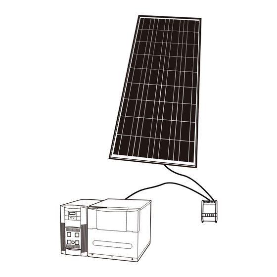
- Page 40 Installation Figure 21 Wiring of Solar Panel...
- Page 41 15 Volts to 23.5 Volts. 3. Connect charge controller to PowerHub 1800 Disconnect solar panel to solar charge controller and switch off the PowerHub 1800 with battery inside if switched on. Connect solar charge controller to PowerHub 1800 and make sure the correct polarity connection, positive to positive and negative to negative.
- Page 42 Installation Permanent Wiring (Hardwiring) WARNING: Shock Hazard Hardwiring this equipment should be done by a person with adequate knowledge of electrical and building code requirements. Failure to follow safe installation practices could result in a significant, and possibly lethal, shock hazard. Terminal Access Wiring Terminals Enlargement BEFORE REMOVING INVERTER COVER:...
- Page 43 Installation Recommended Wire Gauges for Input and Output Terminals Terminal Acceptable Wire Gauge Torque to..AC Input (Neutral and Line) #14 AWG 1.3 Nm (11.5 in-lbs) AC Output (Neutral and Line) #14 AWG 1.3 Nm (11.5 in-lbs) AC Ground #14 AWG 1.8 Nm (16.0 in-lbs) DC Input (32 A DC Input/40 A fused) Manufacturer’s recommendation.
- Page 44 Installation Continued from Figure 3. Locate the AC Accessory Plate and remove one or the two of the knockouts depending on whether both input and output wiring will be needed. If only input is needed, then only remove one knockout. 4.
- Page 45 Installation Wiring Plug-and-go (Softwiring) The PowerHub 1800 comes assembled with an AC input cord. This AC cord can be plugged into a 120 Vac outlet on a 120 Vac generator to charge the batteries. Important: The input cord is intended to allow connection to portable generators in non-permanent installations.
- Page 46 Installation AC Input and Output Wiring from a Generator Connect the PowerHub to a This 15 A circuit breaker is only 15 A circuit breaker in the AC required if the generator being Distribution Panel. This AC used doesn’t already have one. Distribution Panel may not be fed with any other AC sources.
- Page 47 Installation AC Input and Output Wiring from the Utility Grid Connect the PowerHub to Connect the PowerHub to a 15 A circuit breaker in the a 15 A circuit breaker in the Main AC Distribution AC Distribution Panel. This Panel. AC Distribution Panel may not be fed with any other AC sources.
- Page 48 Installation DC Wiring with Ground Fault Protection (Renewable Energy Solar Panel; Maximum 400 W) Important: Renewable energy input may require additional hardware to be code-compliant. There may also be additional grounding requirements. Be sure to consult your local electric authority for additional requirements. Example only.
- Page 49 Installation DC Wiring with Ground Fault Protection (Renewable Energy Solar Array; Maximum 1000 W) Important: Renewable energy input may require additional hardware to be code-compliant. There may also be additional grounding requirements. Be sure to consult your local electric authority for additional requirements. Example only.
- Page 50 Installation DC Wiring (Renewable Energy Wind, Maximum 1000 W) Important: Renewable energy input may require additional hardware to be code-compliant. There may also be additional grounding requirements. Be sure to consult your local electric authority for additional requirements. Example only. Actual installation may vary. IMPORTANT: Wind turbines must be self- regulated.
- Page 51 Installation Replacing the Top Cover 1. Place the top cover back on the inverter and align the holes. 2. Replace the 5 #6-32 Phillips screws on the top of the inverter. 3. Torque to 1.3 nm (11.5 in-lbs) Replacing the Top Cover on the Inverter Double-check Before applying power, double-check the following connections.
- Page 52 Installation To Power Up the PowerHub 1800: Connect the Battery Box to the Inverter Connect the Solar charge controller Press ON/OFF Switch to turn ON Inverter/Charger Connect the Solar panel Open Inverter Output breaker. Connect the Loads Sub-Panel Connect the Loads...
- Page 53 Installation To Power Down the PowerHub 1800: Disconnect Loads connected to Disconnect any loads directly the PowerHub through AC connected to the front panel of Distribution Panel (Sub-panel) the PowerHub by opening the Inverter Output Circuit Breaker. Press ON/OFF Switch to turn OFF...
-
Page 54: Power Up Procedure
Installation Power Up Procedure If softwired..To Power Up the PowerHub 1800: AC Generator 120 Vac Outlet Connect the PowerHub to the generator and turn the generator ON (if required). Connect the Battery Box(es) to the Inverter. Press ON/OFF Switch to turn ON Inverter/Charger. - Page 55 Installation If hardwired..To Power Up the PowerHub 1800: Connect the Battery Box(es) to the Inverter Connect the DC Input Connect the AC Input Press ON/OFF Switch to turn ON Main Panel Inverter/Charger Apply DC Input power by closing Apply Utility power (if available)
- Page 56 Installation Power Down Procedure If softwired..To Power Down the PowerHub 1800: Disconnect Loads. Press ON/OFF Switch to turn OFF Inverter/Charger. Disconnect the Battery Box(es) from the Inverter. Disconnect the PowerHub from the generator and turn the generator OFF. Power Down Procedure for Softwired Installations...
- Page 57 Installation If hardwired..To Power Down the PowerHub 1800: WARNING: Shock Hazard If no DC Disconnect is used, then the DC input generators (solar Panels or wind turbines) will have to be physically disconnected to ensure power is OFF. Disconnect Loads connected to...
-
Page 58: Ground Fault Protection
Installation Ground Fault Protection WARNING: Shock hazard Troubleshooting a grounding fault should be performed by qualified personnel, such as a certified electrician or technician. Ground fault protection is required when using either solar renewable energy input. Figure 3 shows the location protection terminals and replaceable fuse. - Page 59 Installation To replace the ground fault protection fuse: 1. Remove the five Phillips screws on the top of the inverter and lift off the panel to expose the terminals, as shown in Figure 3 . 2. Locate the PV ground fault protection fuse. 3.
-
Page 60: Specifications
Specifications Appendix A provides specifications for Solar Panel Solar Charge controller and PowerHub 1800. - Page 61 Specifications Specification of Solar Panel Parameter Values Unit Poly crystal Si Cells 6.14”x6.14” square Operating temperature -40 +85 Up to 1 Number of cells 4x9 pieces in series Hail diameter @ 49.7mph inch Typical application 12V DC Surface maximum load capacity Up to 2400 Maximum voltage 1000V DC...
- Page 62 Specifications Specification of Solar Charge Controller Parameter Name Default Value...
-
Page 63: Electrical Specifications
Specifications Electrical Specifications Electrical Specifications for the Inverter Parameter PowerHub 1800 Inverter Maximum Output Power 1800 W (15A) (5 minutes maximum) Continuous Output Power 1440 W (12 A) Surge Rating 2880 W (24 A) Input Voltage Range 10.5 to 15.0 Vdc... -
Page 64: Physical Specifications
Specifications Physical Specifications Physical Specifications of the Inverter Parameter PowerHub 1800 Dimensions (H x W x L) 14.75" × 8.0" × 16.0" (37.5 cm × 20 cm × 41 cm) Weight 28.6 lb (13.0 kg) Operating Temperature 0 °C (32 °F) to 40 °C (104 °F) Storage Temperature -30 °C (-22 °F) to 70 °C (158 °F) - Page 65 Specifications Float Stage In the Float stage, the constant voltage mode limited to 13.7 Vdc. An 8- hour timer is started at this point. If, during the 8-hour timer, the current rises to 6 A, the unit transitions back to the Bulk Stage and starts over. If the unit stays at 4A or less for the 8 hour timer, it will transition to Standby Mode.
- Page 66 Specifications Charging Profiles 40-amp Charging Profile Table 7 provides the specific charging parameters for the 40 Charging Profile. 40-amp Charging Profile Parameter Name Default Value Charger Setting 40 A Maximum Bypass Current 500 W (4 A) Bulk Mode 40 A Absorption Mode 14.2 Vdc (4 hours maximum) Float Mode...
- Page 67 Specifications 10-amp Charging Profile Table provides the specific charging parameters for the 10 Charging Profile. 10-amp Charging Profile Parameter Name Default Value Charger Setting 10 A Maximum Bypass Current 1200 W (10 A) Bulk Mode 10 A Absorption Mode 14.2 Vdc (4 hours maximum) Float Mode 13.7 Vdc (8 hours) Switches from Absorption to...
- Page 68 Xantrex Technology Inc. Phono Solar Technology Co., Ltd. Add: 13400 S. Route 59, Suite 116 #105, Plainfield, 1 800 670 0707 Tel toll free NA IL 60585, USA 1 360 925 5097 Tel direct 1 800 994 7828 Fax toll free NA...
Need help?
Do you have a question about the PowerHub 1800 and is the answer not in the manual?
Questions and answers