Casio QT-2000 Service Manual
Electronic
Hide thumbs
Also See for QT-2000:
- User manual (22 pages) ,
- User manual (3 pages) ,
- User manual (3 pages)

Related Manuals for Casio QT-2000


Summary of Contents for Casio QT-2000
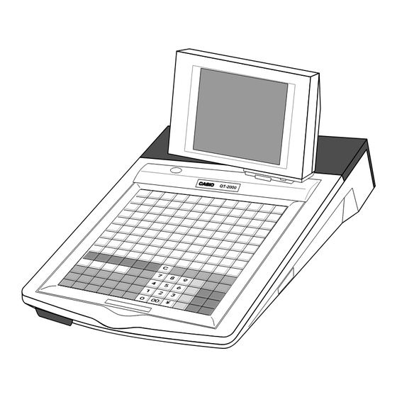
- Page 1 SERVICE MANUAL (without price) ELECTRONIC CASH REGISTER QT-2000 (EX-580) JUNE 1997...
-
Page 2: Table Of Contents
4. INITIALIZE OPERATION ..................11 4-1. To initialize QT-2000 terminal ................ 11 4-2. To initialize QT-2000 terminal(add/replace one QT-2000) ......14 4-3. To flag clear QT-2000 terminal(INIT2, Restore from flash) ......17 5. CIRCUIT EXPLANATION ..................18 5-1. Block diagram (MAIN PCB E580-1)............... 18 5-2. -
Page 3: General
CLK-K18 (15 clerk) HHS-9 Scanner TM-T88 UP-350 The QT-2000 has the following unique points: (The system configuration is shown in the chart above.) 1. Separete R/J printer 2. Small foot-print and low-profile design 3. LCD display : Max. 2 LCD display 4. -
Page 4: Device List (Option)
1-2. Device list (Option) Model Name Device Name Note Sheet holder SH-KIT1 Sheet holder kit 2 holders (1st - 4th, 5th - 8th) Kitchen Printer KP-200 Kitichen printer KP-300 Kitchen printer with auto cutter Slip printer SP-1200 Slip printer R/J printer SA-3015 R/J and slip printer TM-U950... -
Page 5: Specifications
2. SPECIFICATION 2-1. QT-2000 120V 230V Power consumption In operation Max.: 0.7A 0.4A Stand-by Max.: 0.4A 0.3A Mode SW OFF Max.: 0.3A 0.2A Memory Standard: 384 KB Max: Memory protection Back up battery Lithium-Banadium battery VL3032/S6A Back up period 30 days ( 25°C ) - Page 6 2-2. Printer 2-2-1. Model name : SA-3015 Item Description Printer name TM-U950 +24V DC ±10% Power source Current consumprion Average : Approx. 1.8A Max : Approx. 8A Slip Average : Approx. 2.3A Standby : 0.3A Print method Serial impact dot-matrix printer MCBF 5,000,000 lines (auto-cutter and stamp once every 15 lines) Print speed...
- Page 7 2-2-3. Model name : UP-350 (TM-T88) Item Description Printer name TM-T88 +24V DC ±7% Power source Current consumprion Average : Approx. 1.5A Max : Approx. 5.0A Standby : Approx. 0.2A Print method Line thermal printing method MCBF 10,000,000 lines (font A printing) Print speed High speed : 16.5 lines/sec.
- Page 8 2-4. Kitchen printer Model name : KP-300 Item Description Printer name DP-617 Power source AC115V / AC230V Current consumprion Print method Serial impact printing method Both direction printing MCBF Printer mechanism : 2,500,000 lines Head : 50,000,000 character Print speed 2.4 lines/sec.
- Page 9 2-6. MCR Model name : QT-2046MC Item Description Model Name ZU-M1242S4 Card feed Manual operation Data read direction One way (from right to left) Read/Write Read only Magnetic card ISO 7810 , ISO7811 Magnetic stripe encode Track 1: ISO1(IATA) Track 2 : ISO2(ABA) Size 90 mm (L) x 25 mm (W) x 24 mm (H) Weight...
-
Page 10: Qt-2000 Connector Locations
3. QT-2000 CONNECTOR LOCATIONS 3-1. QT-2000 connector location Power switch RS-232C Com1 RS-232C Com2 Slip printer port KP In-line In-line Drawer cable RS-232C Com3 Bottom view Infrared port Com 1 : for hand held scanner HHS-9 Com 2 : for R/J printer (UP-350, SA-3015 and TM-T85) - Page 11 3-2. Interface pin asignment Com1: Hand held scanner HHS-9 (Location : CN2 on E580-CNB) Pin No. Description TXD1 RXD1 RTS1 CTS1 DSR1 DTR1 Com2 : R/J printer (Location : CN1 on E580-CNB) Pin No. Description RXD2 TXD2 DTR2 DSR2 RTS2 CTS2 Com3 : Modem / PC (Location : CN4) Pin No.
- Page 12 Slip printer : SP-1200 (Location : CN10) Pin No. Description Sensor signal Busy signal NACK signal GNDP GNDP Data signal GNDP Clock signal Clear signal Reset signal GNDP GNDP Kitchen printer : KP-200, KP-300 ( Location : CN2) Pin No. Description TXD (Red wire) RXD (Black wire)
-
Page 13: Initialize Operation
4-1.To initialize QT-2000 terminal Preparation: 1. All peripheral devices and QT-2000 terminals of this cluster should be turned off. 2. Connect all of the peripheral devices (such as printer, display etc.) to QT-2000 terminal. 3. Connect all QT-2000 terminals by in-line. Operation: 4. - Page 14 11. In this field, you can select, “1.Non/2.SA-3015/3.SP-1200” for slip printer. Date 97-12-15 Please select one of these options and press the <Yes> key. Time 12:34 00 ID Character MC #01 Check System Master KP System Master R/J/Order Printer SA-3015 Slip Printer SA-3015 Rear Display...
- Page 15 Program copy from other terminal. INIT 97-12-15 12:34 000000 15. In this field, you can select the receiving contents as “1.All Data (including totalizer)/2.All PGM (program only).” Received Data All PGM PGM Receive from MC #05 INIT 97-12-15 12:34 000000 Received Data All PGM PGM Receive from...
-
Page 16: To Initialize Qt-2000 Terminal(Add/Replace One Qt-2000)
4-2. To initialize QT-2000 terminal (add/replace one QT-2000) Preparation: 1. All peripheral devices and QT-2000 terminals of this cluster should be turned off. 2. Connect all of the peripheral devices (such as printer, display etc.) to this QT-2000 terminal. 3. Connect this QT-2000 terminal to in-line. Operation:... - Page 17 Date 97-12-15 11. In this field, you can select, “1.Non/2.SA-3015/3.SP-1200” Time 12:34 00 for slip printer. ID Character MC #01 Check System Master Please choose former options and press the <Yes> key. KP System Master R/J/Order Printer SA-3015 Slip Printer SA-3015 Rear Display Remote Display...
- Page 18 Program copy from other terminal. INIT 97-12-15 12:34 000000 Received Data All PGM PGM Receive from MC #05 15. In this field, you can select the receiving contents as “1.AllData (including totalizer)/2.All PGM (program only).” INIT 97-12-15 12:34 000000 Received Data All PGM PGM Receive from MC #05...
-
Page 19: To Flag Clear Qt-2000 Terminal(Init2, Restore From Flash)
4-3. To flag clear QT-2000 terminal (INIT2, Restore from flash) Preparation: 1. All peripheral devices and this QT-2000 terminal should be turned off. 2. Check the connection of all peripheral devices (such as printer, display etc.) of this QT-2000 terminal. -
Page 20: Circuit Explanation
5. CIRCUIT EXPLANATION 5-1. Block diagram (MAIN PCB E580-1) LCD display IN-LINE ARCNET IC10 ARCNET Controller MASS memory control IC36 IC26 Display controller Drawer IC11 IC20 Keyboard Video RAM Kitchen Printer Slip IC35 IC39 IC31 Printer IC12 IC22 IC43 Back SRAM SRAM EP ROM... -
Page 21: Memory Map
5-2. Memory map 00000h SYSTEM RAM 2Mb x 1 20000h Option RAM 1Mb VRAM Option RAM 4Mb 256Kb x 2 40000h RAM 1Mb x 1 60000h 16Mb FLASH ROM Bank16 80000h A0000h C0000h E0000h EP ROM FFFFFh 40000h VRAM for LCD1 48000h Control area for LCD1... -
Page 22: I/O Address Map
5-3. I/O Address map Interrupt status port There are 8 bits data for status per 1 port. 0000h Rererved System 000h (INT Status) 1000h Port #1 100h System 200h Port #2 2000h Port #3 300h System Port #4 400h 3000h Port #5 500h System... -
Page 23: Lsi Pin Description
5-4. LSI pin description 1. CPU (uPD70108HGC-16-3B6) Pin No. Name Description I n / O u t 1 A18/PS2 Address bus (A18) / Processor status 2 A17/PS1 Address bus (A17) / Processor status 3 A16/PS0 Address bus (A16) / Processor status 4 A15 Address bus (A15) 5 VDD... - Page 24 2. GA1(MN53040KSF1) Pin No. Name Description I n / O u t 1 E49MX2 Sub clock 4.92MHz 2 SVSS 3 EADB0 Address bus (EADB0) 4 EADB1 Address bus (EADB1) 5 EADB2 Address bus (EADB2) 6 EADB3 Address bus (EADB3) 7 EADB4 Address bus (EADB4) 8 EADB5 Address bus (EADB5)
- Page 25 Pin No. Name Description I n / O u t 51 EAD1 Address / Data bus (AD1) In/Out 52 EAD2 Address / Data bus (AD2) In/Out 53 EAD3 Address / Data bus (AD3) In/Out 54 EAD4 Address / Data bus (AD4) In/Out 55 EAD5 Address / Data bus (AD5)
- Page 26 Pin No. Name Description I n / O u t 101 EWR Write strobe signal from CPU 102 EHLADK Hold acknowledge signal from CPU 103 EHLDRQ Hold request signal to CPU 104 _ERD Read signal 105 _E1WT 106 _E2WT 107 _EDCR1 Data clear signal for back display 108 VDD 109 _EDNK1...
- Page 27 Pin No. Name Description I n / O u t 21 _KO7 Key common signal (KO7) 22 _KO6 Key common signal (KO6) 23 _KO5 Key common signal (KO5) 24 _KO4 Key common signal (KO4) 25 _KO3 Key common signal (KO3) 26 VSS 27 _KO2 Key common signal (KO2)
- Page 28 Pin No. Name Description I n / O u t 71 CASHSW2 Clerk switch signal 72 CASHSW1 Clerk switch signal 73 _SLIPSEN Sensor signal from slip printer 74 OBRCLK Not used 75 OBRDATA 76 VSS 77 _DR4 Not used 78 _DR3 Not used 79 _DR2 Drawer open signal (DR2)
- Page 29 4. GA3 (MN53020KSG) Pin No. Name Description I n / O u t 1 VSS 2 XO Clock signal 3 SVDD 4 _CLOCK Not used 5 _ENABLE Not used 6 WMF1 7 WMF2 8 WMF3 9 WMF4 10 WMF5 11 WMF6 12 WMF7 13 WMF8 14 WMF9...
- Page 30 Pin No. Name Description I n / O u t 51 VSS 52 USD0 Data bus for USART (USD0) In/Out 53 USD1 Data bus for USART (USD1) In/Out 54 USD2 Data bus for USART (USD2) In/Out 55 USD3 Data bus for USART (USD3) In/Out 56 USD4 Data bus for USART (USD4)
- Page 31 5. GA4 (MN56020KSJ) Pin No. Name Description I n / O u t 1 VSS 2 MD2 Data signal for MASS memory (MD2) In / Out 3 MD3 Data signal for MASS memory (MD3) In / Out 4 MD4 Data signal for MASS memory (MD4) In / Out 5 MD5 Data signal for MASS memory (MD5)
- Page 32 Pin No. Name Description I n / O u t 51 VSS 52 AD1 Address / Data bus (AD1) In /Out 53 AD0 Address / Data bus (AD0) In / Out 54 _RFSHOT Not used 55 ASTB Address strobe signal 56 IOXM IO / Memory select signal 57 BUFXRW...
- Page 33 6. NETWORK DRIVER (COM20020BILJP) Pin No. Name In/Out Status Status Status Description of OFF of ON of ON No Token Token A0/MUX Pulse Input. On a non-multiplexed bus, these signals are dirctly connectoed to the low bits of the host address bus. A2/ALE On a multiplexed address/data bus, A0/MUX is tied low, A1 is left open,...
- Page 34 Pin No. Name In/Out Status Status Status Description of OFF of ON of ON No token Token INTR Pulse Interrupt output. This active low signal is generated by the COM20020 when an enabled interrupt condition occurs. INTR returns to its inactive state when the interrupt status condition or the corresponding interrupt mask bit is reset.
-
Page 35: Power Down Detection Circuit
5-5. Power down detection circuit IC48 : Detection IC The power is supplied at CN16 from switching power supply unit. When the VP voltage become more than 22V, the voltage appears at pin No.2 of IC48 through the zener diode ZD2. The detection IC outputs "High"... -
Page 36: Option Ram Circuit
5-6. Option RAM circuit Standard memory capacity : 384 KB To expand the memory capacity, put the option RAM chip on RAM1 or RAM2 position Its convination is as follows; Memory capacity Standard RAM1 RAM2 (Location : IC39) (Location : IC35) 384KB 384KB 512KB... -
Page 37: Option Installation
6. OPTION INSTALLATION 6-1. Clerk key unit (CLK-K17,CLK-K18) 1. Cut off the cable cover from the bottom case. 2. Release the screw which is fixing the keyboard and take tke keyboard out. Cut the cable cover. 3. Insart the cable of clerk key unit and connect to CN5 of Main PCB. Note : Hold the cable using a wire clamp to prevent the cut of wire. -
Page 38: Rear Display (Qt-2060D)
6-2. Rear Display (QT-2060D) 1. Release the screw which is fixing the keyboard and take tke keyboard out. 2. Remove the rear display window. Rear display window Release these screws Slide the keyboard to the allow direction 3. Mount the display fixing plate (L). 4. -
Page 39: Mcr Unit (Qt-2046Mc)
6-3. MCR Unit (QT-2046MC) 1. Release the screw which is fixing the keyboard and take tke keyboard out. 2. Remove the Main PCB and solder the connector which is in the QT-2046MC carton to the location CN1 on Main PCB. 2. -
Page 40: Multi Drawer (Mdl-8)
6-4. Multi drawer (MDL-8) 1. Release the screw which is fixing the keyboard and take tke keyboard out. 2. Round the cable of connector sub ass'y for drawer to ferrite core as following figure. 2. Remove the Main PCB and mount the following pars. 3. -
Page 41: In / On Line
Install the I/O-PB-12 in the PC. Note: When the cluster has more than 8 QT-2000 terminals, all printer should be local printer. When the cluster has less than or equal to 8 QT-2000 terminals, remote printer is allowable. In-line Total Length :... - Page 42 C-In line cable, Connector, and Terminater C-In line cable Code No. Parts name Specification 1904 4023 In-line cable IPEV-SLA0.5x1P C-In line connector(ECR side) Code No. Parts name Specification 3500 5820 In-line connector kit XLP-KIT-1 C-In line connector (PC side) Code No. Parts name Specification 1904 4069...
- Page 43 Cable connection diagram (PC and MasterECR) Signal Signal FG plate Disconnect (PC side) (ECR side) Termination 'R in series are connected at pins 1 and 4 of two connectors at both the ends of the in-line cable. Fold the shield and fasten by wrapping copper tape.
-
Page 44: On Line
QT2000 KP/M CHK/BM CHK/M KP/BM Slip Slip Slip Using Com3 port 1-2. Cable wiring QT-2000 (Com3) Pin No. Signal name Pin No. Pin No. Signal name (DSUB9) (DSUB25) SD / TXD RD / RXD RS / RTS CS / CTS... -
Page 45: Modem System
Connection layout nals. Note: When the cluster has more than 8 QT-2000 terminals, all printer should be local printer. When the cluster has less than or equal to 8 QT-2000 terminals, remote printer is allowable. on-line MAX : 15 m... -
Page 46: Kitchen Printer Connection
MAX : 1,000 m QT2000 QT2000 QT2000 QT2000 KP/M CHK/BM CHK/M KP/BM Slip Slip Slip Up to 4 QT-2000 terminals 2) Connector and cable Cable Code No. Parts name Specification 1904 4023 In-line cable IPEV-SLA0.5x1P Connector (ECR side) Code No. Parts name... - Page 47 3) Cable connection diagram (ECR and Kitchen printer) Signal Signal FG plate Disconnect (ECR side) (KP side) [Connection for Kitchen printer side] Termination 'R in series are connected at pins Solder the cable as above wiring. 1 and 4 of two connectors at both the ends of the in-line cable.
- Page 48 4) Kitchen printer controll setting DIP switch setting for kitchen printer model KP-200 and KP-300 are as follows; When the the DIP switch is changed, it is necessary to make initilize the kitchen printer. Otherwise, DIp switch status can not read the CPU inside the controll board. To make initilize, pressing "LF"...
-
Page 49: Diagnostic Operation
8.DIAGNOSTIC PROGRAM 1. Starting the diagnostic program (1) While holding down the button on the upper left corner (9 on the standard keyboard sheet), turn the power on. (2) Release the button when the cash register beeps a buzzer sound. (3) Using 10-key pad, input [9][9][9][9][9][0][0][0][0][0] then press [SUB TOTAL]. - Page 50 Command Device to be checked Operation Note code Standard LCD Optional LCD Flash memory Read/Write/Clear test ARCNET ARCNET ID set ARCNET ARCNET baud rate, token ARCNET ARCNET token stop ARCNET nm41 ARCNET data transmit ARCNET nm42 ARCNET data receive 3. Diagnoses (1) Dot/7-segment display test Operation: [n][0][1][SUB TOTAL] (for the rear display)
- Page 51 (2) R/J Printer test (RS-232C COM2) Prints B’s on RS-232C printer for specified times. Operation: [n][0][3][SUB TOTAL] n = Number of execution and should be within the range of 0 to 9. If no number or “0” is input, the test continues endlessly. To stop the test, press [ESC].
- Page 52 (4) Keyboard test The display shows pressed button number when the key switch functions correctly. Operation: [0][5][SUB TOTAL] Press buttons and make sure that the pressed button number is displayed on the LCD. Note:As [ESC] (button number159) button exits the diagnosis program, press [ESC] at the end. Display: <LCD>...
- Page 53 (5) OBR test Use only the checker bar code in which data 49401387 is written. The program checks if the read data is 49401387. Operation: [n][0][6][SUB TOTAL] n = Number of execution and should be within the range of 0 to 9. If no number or “0”...
- Page 54 (6) MCR test Use only the checker magnet card. Operation: [n][0][7][SUB TOTAL] n = Number of execution and should be within the range of 0 to 9. If no number or “0” is input, the test continues endlessly. To stop the test, press [ESC]. Display: <LCD>...
- Page 55 (8) Buzzer test Beep every 100 milliseconds. In one test, 2 buzzer sound. Operation: [n][1][0][SUB TOTAL] n = Number of execution and should be within the range of 0 to 9. If no number or “0” is input, the test continues endlessly. To stop the test, press [ESC].
- Page 56 (10) Clock test Operation: (1) Press [0][1][2][SUB TOTAL] Display indicates date 99 12 31 MON, time 23 59 55. If [1] is input instead of the first [0], the display shows the present time. <LCD> <Dot/7-segment> CLOCK 99 12 31 23 59 55 Counts up Dot/7-segment display indicates 0 only when...
- Page 57 $tp.exe config.env ini.exe ROM SUM CHECK CREATE 97-04-17 11:53 Copywright (C) 1997 CASIO COMPUTER CO., LTD All rights reserved. ROM VER. AAFAB3075 Indicates “ESC” when the test is finished forcibly by [ESC]. R/J Print: config cpyright cmndrv.exe fsys.exe...
- Page 58 (12) RAM Read/Write test Performs read after write test on RAM addresses 20000H to 3FFFF. Operation: [n][1][4][SUB TOTAL] n = Number of execution and should be within the range of 0 to 9. If no number or “0” is input, the test continues endlessly. To stop the test, press [ESC].
- Page 59 (14) Mass RAM Read/Write test Using the gate array and the CPU in QT-2000 circuit, the program performs RAM’s mass data (in 128k byte unit) read after write test. The program does not diagnose VRAMs. Operation: [n][1][6][SUB TOTAL]. n = Number of execution and should be within the range of 0 to 9.
- Page 60 (16) Low inline data transmission test Connect two QT-2000s with a standard inline cable (RS-485). Inline cable: RS-485 Reciever Command code: 21 Sender Command code: 20 Perform the reception unit operation first then the transmission unit. Operation: [n][m][2][0][SUB TOTAL] n = Number of execution and should be within the range of 0 to 9. If no number or “0”...
- Page 61 (17) Low inline data reception test Connect two QT-2000s with a standard inline cable (RS-485). Perform the reception unit operation first then the transmission unit. Operation: [n][m][2][1][SUB TOTAL] n = Number of execution and should be within the range of 0 to 9. If no number or “0”...
- Page 62 ASYNC ONLINE (19) Infrared Prepare two units of QT-2000 and set both units on the diagnostic mode. Face both units so that they can commu- nicate by the infrared ports. Prepare 2 machine and touch each IR I/F.
- Page 63 Operation: (1) On the receiving unit, press [3][0][SUB TOTAL]. The LCD on the receiving unit indicates; ASYNC RX (2) On the transmission unit, press [n][3][1][SUB TOTAL]. n= Number of execution and should be within the range of 0 to 9. If no number or “0”...
- Page 64 (20) LCD test Operation: [n][3][2][SUB TOTAL] (for standard LCD) [n][3][3][SUB TOTAL] (for optional LCD) n = Number of execution and should be within the range of 0 to 9. If no number or “0” is input, the test continues endlessly. To stop the test, press [ESC].
- Page 65 (21) Flash memory read/write/clear test Performs read after write check on each bank of the flash memory. At the end of the test, all the data in the flash memory are cleared. The following table illustrates the relation between the address and the bank of the flash memory. 60000h Bank 1 Bank 9...
- Page 66 (22) ARCNET test-1 (ID number setting) Sets ID number of ARCNET. Be sure to perform this program before doing the following ARCNET tests. Operation: [m][m][m][3][8][SUB TOTAL] mmm = ID number (001 to 253) Display: <LCD> <Dot/7-segment> ARC - ID ARCNET MY - ID: xxx ID No.
- Page 67 (24) ARCNET test-3 (ARCNET communication stop) Terminates the ARCNET communications. Operation: [4][0][SUB TOTAL] Display: <LCD> <Dot/7-segment> ARC–STP or “NG” Dot/7-segment display indicates 0 only when the test is continued from the “Dot/7-segment display test.” When the test is performed R/J print: indipendently, the dot/7-segment display indi- cates nothing.
- Page 68 Operation: (1) Connect QT-2000s with ARCNET (inline) cable. (2) On the reception unit, press [n][m][m][m][4][2][SUB TOTAL]. n = number of execution. Should be within 0 to 9. If 0 or no number is input, the execution continues endlessly. mmm = ID number of the unit from which the data is sent. To stop the test press [ESC].
-
Page 69: Error Code List
9. ERROR CODE LIST 9-1. Error message When an error occurs on the QT-2000 terminal, buzzer sounds and the error message appears on the main LCD screen. The following table lists the error messages and descibes the action to takae. - Page 70 Prompt message Meaning CHECK# not found E053 CHK/TBL No. is not opened. CHECK# range over E054 Out of CHK/TBL No. Range Printer offline. "****" means ECR logical ID or ********** KP1 ~ KP4. E060 Printer offline. Printer downed. "****" means ECR logical ID or ********** KP1 ~ KP4.
- Page 71 Prompt message Meaning ********** E107 Both Master&Backup master down. CHK M/BM down "****" means ECR logical ID. CHK/TBL tracking or Clerk inter- rupt is not available. ********** Master down then take it off from system "****" means E108 CHK/TBL Master is removed from ECR logical ID.
- Page 72 9-2. System error code Thses error codes are displayed or printed on error log report. l l i e l l l l i i t i i l a l l i e l l i t a l l i e t i "...
- Page 73 i t a i t a l e t t i l l e t t i l l e t t i l i t a i l - i l - i t a e l i i t a i l - i l - i l -...
- Page 74 t a t i l - 9-3. Operation prompt All prompt messages, together with descriptions and symbol characrer for printing on receipts, slip or reports are contained in the listbelow. These messages connot be added, modified or deleted. Prompt message Meaning Request to check the data which cannot be printed Data cannot be printed out.
-
Page 75: Ic Data
10. IC data 1. COM20030BILJP 2. TC7S04F 3. TC7S08F 4. TC7S32F 5. TC4SU69F — 73 —... - Page 76 6. SED1351F0A I/O CONTROL CONTROL REGISTER ADDRESS DISPLAY BUFFER TIMING CONTROL DATA 16BIT BUFFER REFRESH DISPLAY VRAM TIMING LOGIC ADDRESS DATA CONTROL COUNTER CONTROL — 74 —...
- Page 77 7. LH28F016SUT — 75 —...
- Page 78 8. UPD70108HGC — 76 —...
- Page 79 10. TC74HC02 9. TC74HC00 11. TC74HC137 12. TC74HC157 14. TC74HC245 13. TC74HC244 — 77 —...
- Page 80 16. TC74HC4049 15. TC74HC373 17. TC74HC4050 18. TC74HC74 19. TC74HC751178 — 78 —...
- Page 81 20. M51957BFP POWER POWER INPUT OUTPUT INPUT OUTPUT DELAY VALUE DELAY VALUE 21. M5291FP DRIVER COLLECTOR PEAK CURRENT DETECTION EMITTER STD VOLTAGE SUPPLY CLOCK POWER COMPARATOR 1.17 VOLTAGE EARTH COMPARATOR INPUT 23. SN75189 22. SN75188 — 79 —...
-
Page 82: Pcb Layout
11.PCB LAYOUT TOP VIEW — 80 —... - Page 83 Bottom View — 81 —...
-
Page 84: Circuit Diagram
12.CIRCUIT DIAGRAM CONTENTS QT-2000 DESCRIPITION DRAWING NO. PRINTED BOARD NO. BLOCK DIAGRAM E240446 MAIN PCB(1/9) E140201 E580-1 (1/9) MAIN PCB(2/9) E140201 E580-1 (2/9) MAIN PCB(3/9) E140201 E580-1 (3/9) MAIN PCB(4/9) E240447 E580-1 (4/9) MAIN PCB(5/9) E240447 E580-1 (5/9) MAIN PCB(6/9) - Page 85 SHEET DETECT SWITCH Description: Board No. Drawing No. BLOCK DIAGRAM E240446 — 83 —...
- Page 86 Description: Board No. Drawing No. MAIN PCB E580-1 (1/9) E140201 — 84 —...
- Page 87 Description: Board No. Drawing No. MAIN PCB E580-1 (2/9) E140201 — 85 —...
- Page 88 Description: Board No. Drawing No. MAIN PCB E580-1 (3/9) E140201 — 86 —...
- Page 89 Description: Board No. Drawing No. MAIN PCB E580-1 (4/9) E240447 — 87 —...
- Page 90 Non used pin condition Input side : GND Output side : Not connected Description: Board No. Drawing No. MAIN PCB E580-1 (5/9) E240447 — 88 —...
- Page 91 B : Power supply from VDD. Description: Board No. Drawing No. MAIN PCB E580-1 (6/9) E240447 — 89 —...
- Page 92 Description: Board No. Drawing No. MAIN PCB E580-1 (7/9) E240447 — 90 —...
- Page 93 Description: Board No. Drawing No. MAIN PCB E580-1 (8/9) E240447 — 91 —...
- Page 94 Description: Board No. Drawing No. MAIN PCB E580-1 (9/9) E240447 — 92 —...
- Page 95 Description: Board No. Drawing No. KEY BOARD 1 E240448 — 93 —...
- Page 96 Description: Board No. Drawing No. Description: Board No. Drawing No. KEY SHEET SW E580-E4-2 E440510 KEY BOARD 2 E580-E4-1 E440509 — 94 —...
- Page 97 Description: Board No. Drawing No. Description: Board No. Drawing No. VOLUME E580-E2-1 E440508 IR BOARD E580-IR E440511 — 95 —...
- Page 98 Description: Board No. Drawing No. CONNECTOR BOARD E580-CNB E440512 — 96 —...
- Page 99 Description: Board No. Drawing No. 2nd DISPLAY E580-E2 E240449 — 97 —...
- Page 100 — 98 —...
- Page 101 — 99 —...
- Page 102 — 100 —...
- Page 103 1. CIRCUIT DIAGRAM for SP-1200 1-2. CONTROL BOARD 1-1. BLOCK DIAGRAM Connector for ECR 10P 15P Main P.C.Board (E901-1) 5P 4P Printer Model-290 Lamp — 101 —...
- Page 104 1-3. CONNECTOR WIRING (ECR CONTROL BOARD) — 102 —...
- Page 105 1-4.CONNECTOR WIRING (MAIN CONTROL BOARD — PRINTER) Printer Main P.C.B (Connection) (Not used) ........25 4 R detector ass'y ......24 3 R detector ass'y ......23 4 Pin (Not used) ........22 14 Print solenoid Common ....21 13 Print solenoid C ......20 12 Print solenoid B ......
-
Page 106: Parts List
13. PARTS LIST 1. QT-2000 ....................108 2. MCR ASS'Y(QT-2046MC) ............... 114 3. REAR DISPLAY ASS'Y(QT-2060D) ............116 4. DISPLAY ASS'Y(QT-2063D) ..............118 5. SP-1200 ....................120 6. PRINTER UNIT MODEL-209 ..............122 Notes: 1. Prices and specifications are subject to change without notice. - Page 107 — 105 —...
- Page 108 — 106 —...
- Page 109 — 107 —...
- Page 110 QT-2000 Item Code No. Parts Name Specification Version MAIN PCB BLOCK 6193 3504 Main PCB ass'y E580-1 E240399*1 IC36 2001 9905 LSI/Gate array MN56020KSJ IC12 2003 0755 LSI/Gate array MN53040KSF1 IC32 2003 0771 LSI/Gate array MN53020KSG IC11 2003 0780 LSI/Gate array...
- Page 111 Item Code No. Parts Name Specification Version Resistor/Chip network MNR38H0AJ153 R112 Resistor/Chip carbon film MCR10EZHJ202 Resistor/Chip network MNR34J5AJ472 R32-39,41,69,71-76, Resistor/Chip carbon film MCR10EZHJ101 54 X R78,80,82-86,92,98, R100,108,109,120-145 Resistor/Chip carbon film MCR10EZHJ473 R42,47,54,56,62,106, Resistor/Chip carbon film MCR10EZHJ102 12 X R111,114,116,153-155 R28,48-53 Resistor/Chip carbon film MCR10EZHJ331 R104...
- Page 112 Item Code No. Parts Name Specification Version F1-4 3000 7966 Fuse 452.5 3013 1673 Coil RCH855-181K FT21 Filter/EMI NFM40R11C222T1 FT1-20,22-25,27-39 Filter/EMI NFM840R01G101T1 37 X FT26 Filter/EMI NFM39R12C222T1 3240 2089 Buzzer PKM22EPT-2001 3500 3240 Connector/7P IL-G-7P-S3T2-E CN14 3500 3681 Connector/12P IL-G-12P-S3T2-E CN17,18 3500 5846 Connector 53253-0210...
- Page 113 Item Code No. Parts Name Specification Version 12 6248 0193 Plate/Blind E440472-1 13 6248 0200 Cable/51021-15 E340541-1(#26-350) 14 6248 0763 Connector/51021 E340539C-1 15 6248 0767 Case/F LCD E140125A-1 16 6248 0769 Cover/LCD E240331A-1 17 6248 0878 Cushion/ V LCD E440561-1 18 6248 0879 Cushion/H LCD E440562-1 E580-E2-1 ASS'Y...
- Page 114 Item Code No. Parts Name Specification Version Holder/Cable E440375-1 Terminal/Earth E440398-1 34 6247 7456 Filter/IR E440418-1 Rubber/Foot E412136-1 35 3000 8020 Power supply unit/Switching PS-10055-003 (200V) 35 3000 8021 Power supply unit/Switching PS-10055-004 (100V) 36 6221 4802 Cord/Power M2511(EU,G,DI) 36 3701 0242 Cord/Power MP5004 (EU,UK,DI) 36 3700 4283 Cord/Power M3203 (DI)
- Page 115 Item Code No. Parts Name Specification Version Ferritte core TFC-23-11-14 Screw E440564-1 U.S.A. and CANADA only 57 6247 7449 Stand/Rear R E440415-1 58 6247 7442 Stand/Rear L E440414-1 59 5500 1802 Guide GR-80S 60 6193 4575 E404-E2 ass'y E210694H*3 Screw 3X5 ZMC-3 —...
- Page 116 2. MCR ASS'Y (QT-2046MC) — 114 —...
- Page 117 QT-2046MC Item Code No. Parts Name Specification Version 1 1090 5665 MCR unit ZU-M1242S4 2 6220 5857 Earth plate E410943-1 3 6248 0088 Upper case E210283-4 4 6248 0095 Lower case E210351A-3 5 6248 0756 MCR cable sub ass'y E340562-1 Screw 2.3x8 ZMC-3 2.3X8 ZMC-3 Screw 2.6x8 ZMC-3...
- Page 118 3. REAR DISPLAY ASS'Y (QT-2060D) — 116 —...
- Page 119 QT-2060D Item Code No. Parts Name Specification Version 1 6193 4575 PCB ass'y E404-E2 E210694H*3 2003 0704 LSI M50722-101FP IC1,2 2003 0712 LSI M34203M4-140FP 2101 0294 MOS IC TC74HC74AF-TP1 2101 0961 MOS IC TC4050BF-TP1 2112 0231 MOS IC TC4069UBF-TP1 2220 3720 Transistor 2SC3074-Y 2280 0017 Transistor 2SC1815-GR...
- Page 120 4. DISPLAY ASS'Y (QT-2063D) — 118 —...
- Page 121 QT-2063D Item Code No. Parts Name Specification Version 1 6190 8751 PCB ass'y E404-2 E210694*1 2003 0704 LSI M50722-101FP IC1,2 2003 0712 LSI M34203M4-140FP 2101 0294 MOS IC TC74HC74AF-TP1 2101 0961 MOS IC TC4050BF-TP1 2112 0231 MOS IC TC4069UBF-TP1 2220 3720 Transistor 2SC3074-Y 2280 0017 Transistor 2SC1815-GR...
- Page 122 5. SP-1200 — 120 —...
- Page 123 SP-1200 I t e m Code No. Parts Name Specification Version I t e m Code No. Parts Name Specification Version Control PCB block Inductor EXC-ELSA35 6190 9470 PCB ass'y E901-1 E210517H*2 3 3500 5781 Connector 3pin W-P7503 4 3500 5790 Connector 10pin W-P7910 2001 9832 LSI HD614089FB67...
- Page 124 6. PRINTER UNIT MODEL-290 — 122 —...
- Page 125 PRINTER UNIT MODEL-290 Item Code No. Parts Name Specification Version Driving mechanism components 100 0008 7580 Motor ass'y F250051000 101 0008 7581 Motor gear F250051020 102 0008 7582 C.B. screw M2×3 B010309411 103 0008 7583 Motor mount plate F250002010 104 0008 7584 Shaft holder guide F250002020 105 0008 7585 Guide shaft F250002030...
- Page 126 Item Code No. Parts Name Specification Version Connector 800 0008 7615 Main circuit board ass'y F250601000 810 0008 7587 Cup screw (S tight) M2.5×5 B300302211 Option 1 0008 7616 TOF sensor ass'y F250151000 2 0008 7617 BOF sensor ass'y F250152000 3 0008 7618 Document table 176-085 F250254020 4 0008 7611 C.T.B.S.
- Page 127 MA0900971A...
Need help?
Do you have a question about the QT-2000 and is the answer not in the manual?
Questions and answers