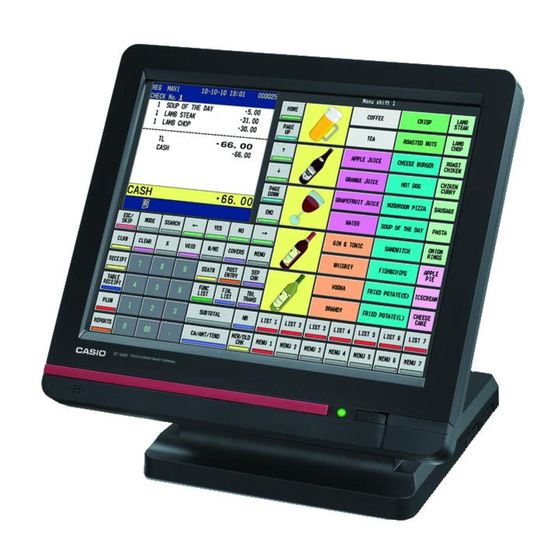
Casio QT-6600 Service Manual
Electronic cash register
Hide thumbs
Also See for QT-6600:
- Reference manual (240 pages) ,
- Programming manual (216 pages) ,
- User manual (92 pages)

Related Manuals for Casio QT-6600


Summary of Contents for Casio QT-6600
- Page 1 SERVICE MANUAL ELECTRONIC CASH REGISTER QT-6600 (EX-830) NOV. 2008 QT-6600 Ver. 5 : Oct. 2014 INDEX...
- Page 2 * Caution ! / Attention ! Battery • Risk of explosion if battery is replaced by an incorrect type. • Dispose of used batteries according to the instructions. Batterie • il y a danger d’explosion si la batterie est remplacée par une batterie de type incorrect. •...
-
Page 3: Table Of Contents
CONTENTS QT-6600 PAGE 1. SPECIFICATIONS ...................1 2. MACHINE INITIALIZATION ..............5 3. DISASSEMBLY ..................10 4. ASSEMBLY ...................24 5. OPTION INSTALLATION ..............36 6. INLINE / ONLINE ...................38 7. DIAGNOSTIC OPERATION ..............40 8. CIRCUIT EXPLANATION ..............81 9. ERROR CODE LIST ................84 10. PCB LAYOUT ..................95 11. -
Page 4: Specifications
<AC input current at Adaptor> In operation Max. 1.5A 1.5A 1.5A 1.5A Display off Max. 0.25A 0.25A 0.25A 0.25A <DC input current at QT-6600> In operation Max. 1.3A 1.3A 1.3A 1.3A Display off Max. 0.5A 0.5A 0.5A 0.5A • Memory protection... - Page 5 1-4. Devices specifications • LCD Display Name NL10276BC30-32D Screen size 15.0 inch (38cm diagonal) Resolution 1024(H) x 768(V) pixels Interface LVDS (RGB 8 bits each) Display color 16.77 M colors Pixel pitch 0.297(H) x 0.297(V) mm Luminance 250 cd/m Contrast ratio 500:1 Power supply voltage 3.3 V...
- Page 6 1-6. Option List CASIO sales options DEVICE NAME MODEL NOTE • Magnet i-Button QT-6011DLS • Display set for customer QT-6060D Connect to Com 3 • Display cable for customer QT-6061CB (for mounting to the base) • Display 5-meter cable for customer QT-6062CB •...
- Page 7 1 year AC adaptor 5 year ■ Installing Precautions When installing QT-6600, attach the ferrite core to the QT-6600 side. Wind the AC adaptor cable around the ferrite core two times. The ferrite core is packed with QT-6600. CAUTION RISK OF EXPLOSION IF BATTERY IS REPLACED BY AN INCORRECT TYPE.
-
Page 8: Machine Initialization
4. Turn on all peripheral devices of a terminal. 5. Turn on this terminal with pressing the initialize switch and release after beep sound. Init Sw INIT Copyright(C) 2008 CASIO COMPUTER CO.,LTD. All rights reserved. ROM VER. xxxxxx xxxx CREATE... - Page 9 • Case 1: If your system has no LAN device = “0” ——— Press <YES> to continue. • Case 2: Terminal ID = “1” IP AD DRE S S MA N U A L ——— Enter IP address if you want to change. 1 9 2 .
- Page 10 Program restoration I N I T 1 0 - 1 0 - 0 1 1 2 : 3 4 0 0 0 0 0 1 AUTO PGM 1 . N o R e s t o r e / R e c e i v e ———...
- Page 11 Operation: 4. Turn on all peripheral devices of this terminal. 5. Turn on this terminal with pressing the <DISP ON/OFF> key. 6. Press <OK> key. Copyright(C) 2008 CASIO COMPUTER CO.,LTD. All rights reserved. ROM VER. xxxxxx xxxx CREATE xxxx-xx-xx xx:xx...
- Page 12 IPL via LAN port Insert more than Store IPL data Backup all data Start 128MB CF card to CF card to CF card IPL from Restore Clear IPL data CF card all data in the CF card 2-4-2. System configuration before IPL operation Connect source terminal (cash register terminal) and target terminals or insert the IPL CF card to the terminal.
-
Page 13: Disassembly
3. DISASSEMBLY NOTE: * Please make a back-up copy of the clients’ data before disassembling. * When the power is turned off, the internal battery enables the hibernate function. * There are several kinds of screws. Be sure to use the correct type of screws when reassembling. - Page 14 ■ Disassembling See the flowchart below for the order of disassembling main parts. A.Removing the Stand B.Removing the B-case Assy Block C.Removing the Rear Display Block D.Disassembling the Rear Display E.Removing the Mic PCB (E830-MIC) F.Removing the LED PCB (E830-E6) G.Removing the Inverter Unit H.Removing the Touch Panel PCB (E830-TP) I.Removing the Power Supply PCB (E830-INLET)
- Page 15 A. Disengage and remove the Main Unit from the Stand. B. Removing the B-case Assy Block B-1. Remove three screws. Screws (S4) B-2. Remove two covers. HNG COVER CONNECTOR COVER — 12 —...
- Page 16 B-3. Remove 12 screws. B-4. Remove the B-case Assy Block. B-5. Unplug the connector to the speaker. Screws (S1) Screws (S2) Screws (S3) Connector (Speaker) B-CASE ASSY BLOCK — 13 —...
- Page 17 C. Removing the Rear Display Block C-1. Remove eight screws. C-2. Remove the connector to the battery. Screws (S6) Connector (Battery) C-3. Remove the Rear Display Block. C-4. Unplug the connector to the Rear Display. Connector (REAR DISPLAY) REAR DISPLAY BLOCK —...
- Page 18 D. Disassembling the Rear Display D-1. Remove the screw and remove the Rear Display Unit. Screws (S5) D-2. Remove two screws and remove the LCD Frame. Screws (S7) D-3. Use a solder to remove six lead wires. D-4. Release the connector lock and disconnect the FPC. D-5.
- Page 19 ■ PCBs and the Connectors to the Main PCB Inverter unit Main PCB (E830-1) Touch panel PCB (E830-TP) COM PCB Power supply PCB (E830-COM) (E830-INLET) LED PCB Mic PCB (E830-E6) (E830-MIC) ■ PCBs and the Connectors to the Main PCB i-Button key Mic PCB (E830-MIC) COM PCB (E830-COM)
- Page 20 E. Removing the Mic PCB (E830-MIC) E-1. Unplug the connector. E-2. Remove two screws and remove the Mic PCB (E830-MIC). Screws (S7) F. Removing the LED PCB (E830-E6) F-1. Unplug the connector. F-2. Remove the screw and remove the LED PCB (E830-E6). Screws (S7) G.
- Page 21 H. Removing the Touch Panel PCB (E830-TP) H-1.Unplug the connector. H-2. Release the connector lock and disconnect the FPC. H-3. Remove two screws and remove the Touch Panel PCB (E830-TP). Screws (S5) Screws (S5) I. Removing the Power Supply PCB (E830-INLET) I-1.
- Page 22 K. Removing the Main PCB (E830-1) K-1. Unplug 10 connectors and 2 FPCs. K-2. Remove six nuts. K-3. Remove seven screws and remove the Main PCB (E830-1). Screws (S9) Screws (S9) Screws (S9) L. Removing the MCR L-1. Disengage and remove the MCR Unit from the Main Unit. L-2.
- Page 23 M. Removing the LCD/Touch Panel M-1. Remove two screws and remove Mic PCB (E830-MIC). M-2. Disengage and remove the MCR unit from the Main Unit. Screws (S7) M-3. Remove two screws and remove the Power Supply PCB (E830-INLET). Screws (S5) M-4.
- Page 24 M-7. Remove five screws and remove the COM Chassis and the Main PCB. Screws (S5) M-8. Remove 17 screws. M-9. Disconnect the earth wire for the Mic. Mic earth — 21 —...
- Page 25 M-10. Remove the U-Case Assy Block. U-CASE ASSY BLOCK M-11. Remove the Touch Panel. Touch panel M-12. Remove four screws. Screws (S10) Screws (S10) — 22 —...
- Page 26 M-13. Disengage and remove the LCD Unit. LCD unit — 23 —...
-
Page 27: Assembly
4. ASSEMBLY ■ Assembling See the flowchart below for the order of re-assembling major units. A. Assembling the LCD/Touch Panel B. Assembling the MCR C. Assembling the Main PCB (E830-1) D. Assembling the COM PCB (E830-COM) E. Assembling the Power Supply PCB (E830-INLET) F. - Page 28 A. Assembling the LCD/Touch Panel A-1. Lay four cables in the appropriate groove. LCD cable Backlight cables Earth cable A-2. Engage the LCD Unit and secure it with four screws. • NOTE: Do not tighten the screws excessively. (Reference torque value: 0.34N m or less) Screws (S10) Screws (S10)
- Page 29 A-3. Engage the Touch Panel. NOTE: Place the Touch Panel evenly inside the guides of the U-case. Guide Guide Touch panel Guide Guide A-4. Engage the U-Case Assy Block. NOTE: Before engaging the U-case Assy Block, be sure that the LCD and the Touch Panel are clean and free of dust, dirt, or any foreign matter.
- Page 30 A-6. Secure it with 17 screws. NOTE: Tighten the screws in the order of the numbers indicated in the illustration below. A-7. Engage the COM Chassis and the Main PCB, and then secure them with five screws. Screws (S5) — 27 —...
- Page 31 A-8. Plug 10 connectors and 1 FPC. NOTE: Do not tangle the wires. A-9. Secure it with seven screws. A-10. Connect the Touch Panel PCB (E830-TP) to the FPC. Screws (S9) Screws (S9) Screws (S9) NOTE: Position it so that the earth terminal Screws (S9) is in the correct orientation.
- Page 32 B. Assembling the MCR B-1. Connect the cables to the MCR Unit. B-2. Engage the MCR Unit and secure it with two screws. B-3. Engage the MCR Unit in the Main Unit. C. Assembling the Main PCB (E830-1) C-1. Engage the Main PCB and secure it with seven screws. C-2.
- Page 33 D. Assembling COM PCB (E830-COM) D-1. Install three COM PCBs (E830-COM) and secure them with two nuts each. D-2. Plug two connectors and the FPC. E. Assembling the Power Supply PCB (E830-INLET) E-1. Engage the Power Supply PCB (E830-INLET) and secure it with two screws. NOTE: two Drawer Cables are arranged under the PCB.
- Page 34 G. Assembling the Inverter Unit G-1. Engage the Inverter Unit and secure it with two screws. G-2. Connect three connectors. Screws (S5) H. Assembling the LED PCB (E830-E6) H-1. Engage the LEC PCB (E830-E6) and secure it with the screw. H-2.
- Page 35 J. Assembling the Rear Display J-1. Engage the Rear LCD PCD (E830-E22). J-2. Use solder to connect six lead wires. J-3. Connect the FPC. NOTE: Engage the FPC securely until it locks in. Black White Green White Black J-4. Engage the LCD Frame and secure it with two screws. Screws (S7) J-5.
- Page 36 Assembling the Rear Display Block NOTE: Check that the cables for the i-Button key receiver and the LED PCB (E830-E6) are contained in the tube. K-1. Plug the connector to the Rear Display and engage the Rear Display Block. Connector (REAR DISPLAY) K-2.
- Page 37 L. Assembling the B-case Assy Block L-1. Plug the connector to the Speaker and engage the B-case Assy Block. NOTE: Insert the B-case in the groove of the Card Cover. Connector (Speaker) L-2. Secure it with 12 screws. Screws (S1) Screws (S2) Screws (S3) —...
- Page 38 L-3. Engage two covers. HNG COVER CONNECTOR COVER L-4. Secure them with three screws. Screws (S4) M. Engage the Main Unit to the Stand. — 35 —...
-
Page 39: Option Installation
5. OPTION INSTALLATION 5-1. To install the I-Button 210mm Wind two turns of cable around the coil. Coil 5-2. REMOTE PRINTER / SLIP PRINTER Connect the following peripherals to the COM ports respectively. REMOTE PRINTER: COM 4, 5 or 6 SLIP PRINTER: COM 2 COM3 COM2... - Page 40 5-3. To install the DRAWER In case of connecting drawer, follow the procedure below. 1. Connect drawer connector (three color lead on drawer) to the terminal. 2. Connect frame drawer connector (green lead on drawer) to the terminal. Mount the cash register. 1.
-
Page 41: Inline / Online
6. IN LINE / ON LINE 6-1. Inline collection/consolidation system • Inline collection/consolidation and auto-programming for up to 32 terminals. Via COM 1 port of the master terminal or Inline (wire or wireless) Maximum 32 terminals 6-2. Online collection / consolidation system •... - Page 42 6-3. Online collection / consolidation system (use FTP feature) • Online collection / consolidation and auto-programming for up to 32 terminals. ADSL/FTTH MODEM Internet ADSL/FTTH VPN rooter MODEM VPN rooter Maximum 32 terminals — 39 —...
-
Page 43: Diagnostic Operation
(3) Release the switch when the screen below appears. * If the switch is released before this screen appears, either of the following modes is launched. • Power-failure recovery reboot • INIT boot-up Copyright(C)2008 CASIO COMPUTER CO.,LTD. All rights reserved. ROM VER. xxxxxx xxxx CREATE... - Page 44 7-2. General Notes on the Diagnostic Program • The test result is printed out through an external printer. Baud rate :9600 bps Connection : COM1 • A scanner must be connected to COM2. • You may select “single test” or “repeat indefinitely” for the number of retries.To repeat the test indefinitely, enter any number except for 0 in the command specifying the number of retries.
- Page 45 7-4. Status Information Shows a screen as shown below on the LCD (XGA). (In this chapter, the area for entries and the area for test results are illustrated separately.) MAC ADRS XX-XX-XX-XX-XX-XX TEMP VOLTAGE CHARGE-MODE 360M DISP ON/OFF INSERT Status information is displayed continuously (in ordinary characters).
- Page 46 7-5. Memory Test Overview 7-5-1.Types of memory tests FLASH ROM FLASH ROM (for programming) (for hibernation) WRITE Test READ ONLY Test CLEAR Test CLEAR & WRITE/READ Test ...
- Page 47 [RAM Test] RAM Test uses, as the test area, all areas except for the program and system areas. USER area is not guaranteed after performing the test. RAM 64MByte 0x0000000 Area for BOOTER 0x0030000 Program/system area Scope of READ ONLY Test USER area Scope of WRITE/READ Test 0x3FDFFEF...
- Page 48 7-6. Test Items This program performs the following tests. Device to be checked Operation Note Page RAM, FROM (for programming), FROM (for hibernation), 1 Batch Test 1 Date/Time, Buzzer, Drawer, Receipt LCD,LCD backlight, REAR 2 Batch Test 2 DISPLAY, REAR DISPLAY backlight 3 RAM WRITE/READ Test n011...
- Page 49 7-7. Test Procedures [ 1 ] Batch Test 1 [Function] Performs the following tests in sequence. (1) RAM Test: RAM WRITE/READ Test (2) FROM (for program) Test Check Sum test for the program code area. (3) FROM (for hibernation) Test Displays/prints out the sum of the FLASH headers for hibernation.
- Page 50 [ 2 ] Batch Test 2 [Function] Performs the following tests in sequence. (1) LCD Test: Performs the LCD Display Test. To change the screen, touch any part of the panel. Reverse Check (black Black White Green Blue and white) check Select the test result "1"...
- Page 51 [ 3 ] RAM WRITE/READ Test [Function] Tests whether writing in/reading RAM is correctly performed. Test data is written on the RAM, and tests are performed to check if the data has been written properly. The areas where performing this test affects the operation are excluded from the test. [Operation] Operation : n n: Number of times...
- Page 52 [ 5 ] FLASH ROM CLEAR Test [Function] Tests whether FLASH ROM Clear erases the memory correctly. After this test, be sure to perform “[6] FLASH ROM WRITE/READ Test” before conducting other tests. If other tests are performed without having conducted FLASH ROM WRITE/READ Test, the program may be damaged and may not operate properly.
- Page 53 [ 6 ] FLASH ROM WRITE/READ Test [Function] Tests whether writing/reading to FLASH ROM is correctly performed. This test targets all areas except for the data protection areas. Be sure to perform “[5] FLASH ROM CLEAR Test” before this test. If other tests are performed without having conducted FLASH ROM CLEAR test, this program may be damaged and may not operate properly.
- Page 54 [ 7 ] FLASH ROM CLEAR & WRITE/READ Test [Function] Clears FLASH ROM memory and tests whether writing/reading is correctly performed. [Operation] Operation : c c: Specifying FLASH ROM FLASH ROM (for programming) FLASH ROM (for hibernation) n: Number of times 0 or no value To perform a single test A value other than 0 (1 ~ 9) Tests repeat infinitely (press ESC to terminate)
- Page 55 [ 8 ] FLASH ROM CHECK SUM Test [Function] Performs CHECK SUM of FLASH ROM. This test is exclusively for FLASH ROM for programming. [Operation] Operation : n n: Number of times 0 or no value To perform a single test A value other than 0 (1 ~ 9) Tests repeat infinitely (press ESC to terminate) [LCD] [PRINT]...
- Page 56 [ 10 ] CF-CARD WRITE/READ Test [Function] Tests whether writing in /reading CF Card is correctly performed. Be sure to perform “[9] CF-CARD CLEAR Test” before this test. After a CF Card is used for this test, the data contained in it and its operation cannot be guaranteed.
- Page 57 [ 12 ] CF-CARD CLEAR&WRITE/READ Test [Function] Clears CF Card memory and tests whether writing/reading is correctly performed. After a CF Card is used for this test, the data contained in it and its operation cannot be guaranteed. [Operation] Operation : n n: Number of times 0 or no value To perform a single test...
- Page 58 [ 13 ] LCD Test [Function] Tests whether LCD operates correctly. When performing a single test: To change the screen, touch any part of the panel. In order to complete the test, the operator must determine pass(OK)/fail(NG) of the result. When performing test infinitely: The screens change automatically.
- Page 59 [ 15 ] LCD Calibration Setting [Function] Configures the calibration settings of the LCD (Touch Panel). When touching the cross marks on the LCD, 10 coordinates shown below are indicated in sequence. (X,Y) = (25,19) (487,19) (999,19) (25,365) ...
- Page 60 [LCD] TOUCH START Enter the Caribration mode ==>> Push Disp on/off key LCD display only Skip the Caribration mode ==>> Touch the panel (X1,Y1) : (XXX,XXX) Displays data 1 for calibration (X2,Y2) : (XXX,XXX) Displays data 2 for calibration (X9,Y9) : (XXX,XXX) Displays data 9 for calibration (Performs offset) (X10,Y10) : (XXX,XXX) Displays the position of the 10th coordinate (performs...
- Page 61 [ 16 ] VRAM CHECK Test [Function] Checks VRAM of the LCD. All areas except for the GDC system area are subjected to this test. VRAM is not backed up by the battery. A power failure during the test results in an error. This test uses the same test data as RAM Test to write on VRAM.
- Page 62 [ 17 ] REAR DISPLAY Test [Function] Tests whether REAR DISPLAY operates correctly. The backlight turns emerald green (white and green) during the test and turns off when the test ends. When performing a single test: To change the screen, touch any part of the panel. In order to complete the test, the operator must determine pass(OK)/fail(NG) of the result.
- Page 63 [ 18 ] REAR DISPLAY Backlight Test [Function] Tests whether REAR DISPLAY backlight operates correctly. In order to complete the test, the operator must determine Pass(OK)/fail(NG) of the result. (When performing a single test) The specified backlight turns on while performing the test and turns off when the test ends. [Operation] Operation : c c: Specifying the backlight color...
- Page 64 [ 19 ] REAR DISPLAY Contrast Adjustment [Function] Adjusts the contrast of REAR DISPLAY and writes the adjustment values on FLASH. FLASH may be written up to 16 times. Writing more than 16 times results in an error. When such an error occurs, you may follow the procedure “Clearing the contrast area”...
- Page 65 [ 20 ] REMOTE DISPLAY Test: [Function] Tests whether the data is correctly displayed on REMOTE DISPLAY. Be sure to connect REMOTE DISPLAY to COM3. When changing the baud rate, be sure to also change the settings on REMOTE DISPLAY. The backlight turns on in pastel green (green + white) when performing the test and turns off when the test ends.
- Page 66 [ 21 ] External Printer Output Test [Function] Connects a printer with a RS232C interface and tests whether the printer operates and prints properly. The external printer must be connected to COM. [Operation] Operation : x1 x2 x3 x1: Printout format Pattern A Pattern B x2: Specify COM port...
- Page 67 d: Specifying a printer External printer RJ External printer SLIP [LCD] RJ is connected Error display (when a printer is disconnected) xxxn03d NON PRINTER ERR xxxn03d [PRINT] There are two formats to print out to the external printer. RJ is set at 40 lines and SLIP at 35 lines. Pattern A Pattern B BBBBBBBBBBBBBBBBBBBBBBBBBBBBBBBBBBBBBBBB...
- Page 68 9100 Baud rate: AutoNegotiation QT-6600 operates with IP address 192.168.0.1 at the fixed baud rate of 100M. * Ethernet does not operate without setting a MAC address. Be sure to set a unique MAC address before use. * If Ethernet has already been tested, run all operations starting from INIT boot-up.
- Page 69 [LCD] xxxn03d EtherPrt EtherPrt When it is NG (communication error, etc.) xxxn03d [PRINT] There are two formats to print out to the external printer. Pattern A Pattern B BBBBBBBBBBBBBBBBBBBBBBBBBBBBBBBBBBBBBBBB BBBBBBBBBBBBBBBBBBBBBBBB *8,888,88 — 66 —...
- Page 70 [ 23 ] COM (RS232C) Test [Function] Performs a loop back test on RS232C port. This test does not generate a printout of the result. To generate a printout, see “[25] Printing COM(RS232C) Test Result.” Please refer to the illustration in "[24] COM(RS232C) Batch Test” for wiring. [Operation] Operation : x x: Specify the baud rate...
- Page 71 [ 24 ] COM (RS232C) Batch Test [Function] Performs a loop back batch test on RS232C port. When performing this test, attach the loop back connecters to all COM ports. Please see below for how to wire. [Operation] Operation : 4 Baud rate: COM1: 115 kbps, COM2-6: 19.2 kbps Number of test: once (fixed) [LCD]...
- Page 72 [ 25 ] Printing COM (RS232C) Test Result [Function] Prints out COM (RS232C) test results. The printer must be connected to COM1 port at 9600 bps. [Operation] Operation : 4 [PRINT] COM1 RTSx=1 → CTSx=1 DTRx=1 → DSRx=1 DTRx=1 → CDx=1 DTRx=1 →...
- Page 73 [ 26 ] Ethernet Test [Function] Tests the Ethernet counter communication. QT-6600 in the reception mode becomes on standby and, then, QT-6600 in the transmitting mode sends data. Once the communication opens properly, the number of successful/failed communication to LCD is displayed on the counter, which will be printed out when the test ends.
- Page 74 a: Transmitting/receiving mode TCP transmitting mode TCP receiving mode Ping transmission Transmitting and receiving continue unless an error occurs. Press ESC to terminate the test. (To terminate the test, operate at the transmitting end.) <Ping transmission> Ping is sent to 192.168.0.10. When a ping is transmitted, the counter adds a value. After terminating it with ESC key, the number of successful/failed communication is displayed.
- Page 75 [ 27 ] Setting MAC (Media Access Control Address [Function] Configures MAC address [Operation] When an ID is set, perform the test with that ID. When you change the ID, run all operations starting from INIT boot-up. Operation : x x: Specifying how to write the address Writes a continual address based on MAC address on CF Card.
- Page 76 [PRINT] When configuring using a CF Card MAC ADDRESS x0951 Write EEPROM : ****** x0951 When configuring manually MAC ADDRESS x0951 1 : 008 2 : 000 3 : 116 4 : 255 5 : 003 6 : 000 Write EEPROM : ****** x0951 —...
- Page 77 [ 28 ] Date/Time Setting [ 29 ] Date/Time Display [Function] Configures or displays the date and time. If [ST] is pressed without an entry while Date/Time Setting, the Date/Time is displayed. [Operation] Date/Time Setting Operation : h hh: Hour, mm: minute, ss: second Operation : y yy: Year, mm: month, dd: day Date/Time Display...
- Page 78 [ 30 ] Drawer Test [Function] Tests whether drawers operate properly. In order to complete the test, the operator must determine pass(OK)/fail(NG) of the result. [Operation] Operation : x x: Drawer No. Opens all drawers. Opens Drawer 1 Opens Drawer 2 n: Number of times 0 or no value To perform a single test...
- Page 79 [ 31 ] Buzzer Test [Function] Tests whether the buzzer operates properly. When performing a single test, one-shot buzzer sounds once. When repeating a test infinitely, the buzzer sounds intermittently for 500 msec. Press ESC key to terminate the buzzer. [Operation] Operation : n n: Number of times...
- Page 80 [ 32 ] MCR Test [Function] Tests whether the card reader (MCR) operates properly. The data read out is compared against the preset data to determine pass(OK)/fail(NG). Track 1: 1234567890123456789012345678901234567890123456789012345678901234567890123456 Track 2: 1234567890123456789012345678901234567 [Operation] Operation : 9 [LCD] MCR1 When it is operating properly MCR2 MCR1 ******************...
- Page 81 [ 33 ] Sound Test [Function] Tests whether sound is replayed properly through the internal or external speaker. In order to complete the test, the operator must determine pass(OK)/fail(NG) of the result. (when performing a single test) [Operation] Operation : a a: Volume Max.
- Page 82 [ 35 ] Charge Mode Test [Function] Turns OFF the Charge Mode [Operation] Operation : 9 [LCD] [PRINT] CAHRGE OFF CAHRGE OFF [ 36 ] OBR Test: [Function] Tests whether the scanner connected operates correctly. The data read out is compared against the preset data to determine pass(OK)/fail(NG). Be sure to connect OBR to COM2.
- Page 83 [ 37 ] PS/2 Keyboard Test [Function] Tests whether the interface operates correctly. An echo command is transmitted to PS/2 interface keyboard to see if there is a correct echo response. It must be a command-response communication, and one transmission is performed per test. If there is an error in data reception or a transmission time-out, the test is repeated the specified number of times.
-
Page 84: Circuit Explanation
8. CIRCUIT EXPLANATION 8-1. HARDWARE DIAGRAM Speaker Flash FROM Memory i-Button key i/f 32MB 64MB 64MB QT-6011DLST (except for QT-6600-DLS) Microphone QT-6046MCR Drawer Drawer MODEM Scanner AC Adptor (HHS-15) Remote Remote printer printer UP-400 UP-400 Power Power Other terminals supply... - Page 85 8-2. BLOCK DIAGRAM — 82 —...
- Page 86 8-3. LSI BLOCK DIAGRAM LCD BACKLIGHT INVERTOR PORT UNIT LCD BACKLIGHT EXTERNAL RTC LVDS LVDS Conversion IC LCD CONTROLLER (GC) REAR LCD 1024 × 768 RGB 24bit DISPLAY Digital FUJITSU LIME CLOCK SYNCHRONOUS Renesas Technology Corp. 160x32dot (MB86276) SERIAL SH7763 PORT x2 LCD BACKLIGHT SDRAM I/F...
-
Page 87: Error Code List
9. ERROR CODE LIST 9-1. Error message This section describes what to do when you have problems with operation. When an error occurs Errors are indicated by an error codes. When this happens, you can usually find out what the problem is as illustrated below. - Page 88 Prompt message Meaning Action E048 Insert Slip Paper and Alarm when no paper is inserted in the Insert new slip paper. retry. Slip. E049 CHECK memory full. Check tracking index full/near end Finalize and close the check number currently used. E050 Detail memory full.
- Page 89 Prompt message Meaning Action ********** Busy at target ECR which has printer E072 Target printer terminal is “****” means ECR logical ID and printer busy. number. ********** Time out at ECR which has printer Follow the prompt message. E073 Your receipt/order may “****”...
- Page 90 Prompt message Meaning Action E150 Incorrect value entry. Incorrect entry for PGM Enter proper value again. E151 Incorrect Key Pressed. Linking is incorrect. Enter proper key again. E152 PGM File or Memory No such file, no such record Enter file/record number again. number does not Exist.
- Page 91 Prompt message Meaning Action E212 Card Expired. Card is expired. This card cannot be used. E213 Card Validation Failed. Card validation is failed. This card cannot be used. E215 Card Format Error. Card format error This card cannot be used. E240 Customer No.
- Page 92 9-2. Operation prompt All prompt messages, together with descriptors and symbol characters for displaying / printing are contained in the list below. These messages cannot be added, modified or deleted. Prompt message Meaning Data cannot be printed out. Request to check the X / Z report data which Backup to R/J printer? cannot be printed out.
- Page 93 9-3. System error code All error codes are contained in the list below. These error codes are displayed or printed on error log report. Error code Meaning 0010 Handler access error (software) 0011 Cannot execute handler (system configuration) 0012 Break by PC 0013 Break by ECR 0014...
- Page 94 Error code Meaning 0079 Z lock release error on satellite terminal 0081 Check tracking master is removed from system. 0082 Check tracking backup master is removed from system. 0128 Parameter error / Maximum length of send error 0130 Error drive 0134 Network parameter error 0138...
- Page 95 9-4. CPU Exceptional Error The functions of the CPU (SH series) include exception handling. If an exception other than reset and general interrupt (hereafter called “general exception”) occurs, the OS displays a message as shown below and stops the operation of ECR, because the operation after that cannot be guaranteed. The example shown below indicates the screen displayed when “reservation instruction code exception”...
- Page 96 Causes of error occurrence (1) error no. 40: TLB address comparison results in address mismatch (2) error no. 60: TLB entry is invalid Description of phenomenon: The CPU performs a conversion from logical address to physical address when accessing the external memory. TLB is what caches that information.
- Page 97 9-5. Booster Error ERR for XXX nn XXX: INIT…INIT error IPL…IPL error Refer to the Error Code Correspondence Table below Error Code Correspondence Table Error No. Description of error CF card is not inserted. CF card is not formatted correctly FROM erase error FROM write error RAM write error...
-
Page 98: Pcb Layout
10. PCB LAYOUT MAIN PCB (E830-1 PCB) (TOP VIEW) — 95 —... - Page 99 MAIN PCB (E830-1 PCB) (BOTTOM VIEW) — 96 —...
- Page 100 REAR LCD PCB (E830-E22 PCB) (TOP VIEW) (BOTTOM VIEW) TOUCH PANEL PCB (E830-TP PCB) (TOP VIEW) (BOTTOM VIEW) INTERFACE PCB (E830-COM PCB) — 97 —...
- Page 101 LED PCB (E830-E6 PCB) (TOP VIEW) (BOTTOM VIEW) INLET PCB (E830-INLET PCB) MIC PCB (E830-MIC PCB) — 98 —...
-
Page 102: Circuit Diagram
11. CIRCUIT DIAGRAM MODEL : QT-6600 (EX-830) CONTENTS 1. MAIN PCB CIRCUIT 2-1.MAIN PCB CIRCUIT (1/13) CPU BLOCK ..............100 2-2.MAIN PCB CIRCUIT (2/13) GRAPHIC CONTROL BLOCK ........101 2-3.MAIN PCB CIRCUIT (3/13) LCD I/f BLOCK ..............102 2-4.MAIN PCB CIRCUIT (4/13) VRAM BLOCK ...............103 2-5.MAIN PCB CIRCUIT (5/13) MAIN MEMORY BLOCK ..........104... - Page 103 External RTC Model PWB No. PWB Name Name QT-6600 CASIO COMPUTER CO.,LTD. MAIN BOARD (1/13) CPU BLOCK E830-1 (EX-830) — 100 —...
- Page 104 Model PWB No. PWB Name Name QT-6600 CASIO COMPUTER CO.,LTD. MAIN BOARD (2/13) GRAPHIC CONTROL BLOCK E830-1 (EX-830) — 101 —...
- Page 105 Model PWB No. PWB Name Name QT-6600 CASIO COMPUTER CO.,LTD. MAIN BOARD (3/13) LCD I/F BLOCK (EX-830) E830-1 — 102 —...
- Page 106 Model PWB No. PWB Name Name QT-6600 CASIO COMPUTER CO.,LTD. MAIN BOARD (4/13) VRAM BLOCK (EX-830) E830-1 — 103 —...
- Page 107 Model PWB No. PWB Name Name QT-6600 CASIO COMPUTER CO.,LTD. MAIN BOARD (5/13) MAIN MEMORY BLOCK (EX-830) E830-1 — 104 —...
- Page 108 Model PWB No. PWB Name Name QT-6600 CASIO COMPUTER CO.,LTD. MAIN BOARD (6/13) FROM & BUFFER BLOCK (EX-830) E830-1 — 105 —...
- Page 109 Model PWB No. PWB Name Name QT-6600 CASIO COMPUTER CO.,LTD. MAIN BOARD (7/13) GATE ARRAY BLOCK (EX-830) E830-1 — 106 —...
- Page 110 Model PWB No. PWB Name Name QT-6600 CASIO COMPUTER CO.,LTD. MAIN BOARD (8/13) LAN & SOUND BLOCK (EX-830) E830-1 — 107 —...
- Page 111 Model PWB No. PWB Name Name QT-6600 CASIO COMPUTER CO.,LTD. MAIN BOARD (9/13) CF-CARD I/F BLOCK (EX-830) E830-1 — 108 —...
- Page 112 Model PWB No. PWB Name Name QT-6600 CASIO COMPUTER CO.,LTD. MAIN BOARD (10/13) RS232C I/F BLOCK (EX-830) E830-1 — 109 —...
- Page 113 Model PWB No. PWB Name Name QT-6600 CASIO COMPUTER CO.,LTD. MAIN BOARD (11/13) I/O CONTROL BLOCK (EX-830) E830-1 — 110 —...
- Page 114 Model PWB No. PWB Name Name QT-6600 CASIO COMPUTER CO.,LTD. MAIN BOARD (12/13) POWER SOURCE BLOCK (EX-830) E830-1 — 111 —...
- Page 115 Model PWB No. PWB Name Name QT-6600 CASIO COMPUTER CO.,LTD. MAIN BOARD (13/13) PWD/RESET & BATTERY BLOCK (EX-830) E830-1 — 112 —...
- Page 116 Model PWB No. PWB Name Name QT-6600 CASIO COMPUTER CO.,LTD. REAR LCD PCB CUSTOMER DISPLAY BORAD E830-E22 (EX-830) — 113 —...
- Page 117 Model PWB No. PWB Name Name QT-6600 CASIO COMPUTER CO.,LTD. TOUCH PANEL PCB TOUCH PANEL I/F BORAD E830-TP (EX-830) — 114 —...
- Page 118 Model PWB No. PWB Name Name CASIO COMPUTER CO.,LTD. INTERFACE PCB COM BORAD QT-6600 (EX-830) E830-COM — 115 —...
- Page 119 Model PWB No. PWB Name Name CASIO COMPUTER CO.,LTD. LED PCB LED/SW BORAD QT-6600 (EX-830) E830-E6 — 116 —...
- Page 120 Model PWB No. PWB Name Name CASIO COMPUTER CO.,LTD. INLET PCB INLET BOARD (DC IN) QT-6600 (EX-830) E830-INLET — 117 —...
- Page 121 Model PWB No. PWB Name Name CASIO COMPUTER CO.,LTD. MIC PCB MICROPHONE BOARD QT-6600 (EX-830) E830-MIC — 118 —...
-
Page 122: Parts List
2. As for spare parts order and supply, refer to the “GUIDEBOOK for Spare Parts Supply”, published separately. 3. The numbers in item column corespond to the same numbers in drawing. 4. CASIO does not supply the spare parts without parts code. 5. Remarks Q'ty :... -
Page 123: Exploded View
EXPLODED VIEW (QT-6600) 2 turn Screw(S11) WASHER 22-1 23-1 23-1 22-1 Cable tie 150mm — 120 —... -
Page 124: Main Pcb Block
1 QT-6600C 2 QT-6600B 3 QT-6600BD Q'ty Price Item Code No. Parts Name Specification Rank Code 1. MAIN PCB BLOCK 10322428 PCB ASSY/E830-1 RJE502811*001V01 10261121 IC BA33DD0WHFP-TR 10275575 IC RV5C348A-E2-FB 10315229 LSI R5S77631AY266BGV 10315230 LSI MB86276PB-G-ZE1 10316453 IC SN75LVDS83DGGR IC6,IC7 10272416 SDRAM MT48LC4M16A2P-75:G IC8,IC9... - Page 125 1 QT-6600C 2 QT-6600B 3 QT-6600BD Q'ty Price Item Code No. Parts Name Specification Rank Code R10,R22,R166,R168, R170,R205,R282, RESISTOR/CHIP WR06X100JTL R417-R420,R423 R16,R17,R19,R25,R26, RESISTOR/CHIP WR06X220JTL R300 R23,R24,R410,R415 RESISTOR/CHIP WR06X1001FTL R27,R302,R303 RESISTOR/CHIP WR06X201JTL R35,R47-R49,R186,R312 RESISTOR/CHIP WR06X430JTL R36,R39,R43,R44,R50, R317,R347,R349-354, R357,R361,R362,R369, RESISTOR/CHIP WR06X101JTL R379,R380,R388,R391, R392,R395,R398,R438, R442 R41,R318,R338,R381,...
- Page 126 1 QT-6600C 2 QT-6600B 3 QT-6600BD Q'ty Price Item Code No. Parts Name Specification Rank Code RM45-RM52,RM55,RM58, RM61,RM64,RM133, REGISTOR ARRAY WA06X000PTL RM160-RM162 RM54,RM57,RM60,RM63, REGISTOR ARRAY WA06X510JTL RM159 RM56,RM59,RM70,RM71, RM73,RM74,RM78-RM81, REGISTOR ARRAY WA06X330JTL RM84-RM87, RM134-RM140 C1-C3,C5-C10,C13-C22, C24-C35,C40,C41, C44-C48,C50,C52-C55, C57-C59,C61,C63, C65-C75,C81-C83, C88-C96,C98-C104, C106-C113,C115-C124, CAPACITOR/CHIP 0402F104Z160CT...
- Page 127 1 QT-6600C 2 QT-6600B 3 QT-6600BD Q'ty Price Item Code No. Parts Name Specification Rank Code CAPACITOR/CHIP 0603B104K500CT C284,C286 C267,C288 CAPACITOR/CHIP GRM31CB31H475KA12L C290-C292 CAPACITOR/CHIP RJ3-16V471MH3# C305 CAPACITOR/CHIP RE3-16V220ME3# C332 CAPACITOR/CHIP RJ4-50V102MI6# 23902058 DIODE 1SR154-400TE25 D5,D6 D3,D4,D11-D15,D18 10009218 DIODE 1SS400TE61 23902436 DIODE/CHIP RB050L-40TE25 DIODE/CHIP RB095B-40TL...
-
Page 128: Final Assy Block
SCREW S-BDMA-3X10B3 SCREW S-BDMA-3X22B3 SCREW S-BDPT-3X20NI SCREW S-BDMA-3X8B3 3. U-CASE ASSY BLOCK 10315480 CASE/UPPER RJE502768-001V01 10244159 TOUCH-PANEL N010-0527-T841 10313710 PLATE/CASIO RJE501249-002V01 10315482 RUBBER/MCR RJE502782-001V01 10315483 LENS/LED RJE502785-001V01 10315484 COVER/DALLAS RJE502788-001V01 10315485 BUTTON/DP RJE502786-001V01 10315486 HOLDER/DP SW RJE502787-001V01 10322431 PCB ASSY/E830-E6... -
Page 129: B-Case Assy Block
1 QT-6600C 2 QT-6600B 3 QT-6600BD Price Q'ty Item Code No. Parts Name Specification Rank Code 10315505 CABLE SUB ASSY/LVDS RJE502817*001V01 10323591 POWER-SW-ASSY RJE502826*001V01 10315507 HOLDER/BAT RJE502789-001V01 10315536 CABLE SUB ASSY/DRW RJE502844*001V01 10078854 JOINER/FFC A-E27 E441341-1 10320743 CABLE SUB ASSY/TP RJE502847*001V02 10320742 CABLE SUB ASSY/INV1 RJE502846*001V02... -
Page 130: Drawer M Type (Dl-2434/Dl-2808/Dl-2809/Dl-2810)
8. DRAWER M type (DL-2434/DL-2808/DL-2809/DL-2810) DL-2808/DL-2809 DL-2434 DL-2810 — 127 —... - Page 131 1 DL-2434 2 DL-2808 3 DL-2809 4 DL-2810 Price Q'ty N Item Code No. Parts Name Specification code 10203171 CASE/FOOT RUBBER RJE500667-001V02 10167366 RUBBER/FOOT RJE501204-001V01 SUB ASSY/BOX RJE502877*001V01 10223071 SUB ASSY/DRAWER E341274*002V04 55000619 ROLLER/DELRIN DR-19B1 52000106 RIVET 5x30 10201065 SPRING/EARTH E412092-001 10203374 LOCK/CYLINDER...
-
Page 132: Drawer L Type (Dl-3622)
9. DRAWER L type (DL-3622) 21 22 23 24 25 26 27 28 29 30 31 — 129 —... - Page 133 DL-3622 (L type) Price N Item Code No. Parts Name Specification Qt'y Rank code 1907 7272 LOCK ASSY ZD00290-0 1906 0672 M4XP0.7 9487 0383 LABEL DL-3616 1907 9613 WIRE/FG ZD31670 1907 0223 CONNECTOR 1625-03PI 1902 7112 GROMET 1902 7076 SPRING ZD01370B 1902 6829 RUBBER/DAMPER...
-
Page 134: Drawer L Type (Dl-3623)
10. DRAWER L type (DL-3623) 21 22 23 24 25 26 27 28 29 30 31 — 131 —... - Page 135 DL-3623 (L type) Price N Item Code No. Parts Name Specification Qt'y Rank code 1907 7935 LOCK ASSY ZD00280-0 1906 0672 M4XP0.7 9487 0384 LABEL DL-3617 1907 9613 WIRE/FG ZD31670 1907 0223 CONNECTOR 1625-03PI 1902 7112 GROMET 1902 7076 SPRING ZD01370B 1902 6829 RUBBER/DAMPER...
- Page 136 Ver. 1 : Apr. 2010 • Correction of the 2. MACHINE INITIALIZATION (P7) Ver. 2 : Jun. 2010 • Correction of the EXPLODED VIEW (QT-6600) (P120) • Correction of the PARTS LIST (QT-6600) (P126) Ver. 3 : Jul. 2013 • Correction of the PARTS LIST (QT-6600) (P125) Ver.
Need help?
Do you have a question about the QT-6600 and is the answer not in the manual?
Questions and answers