Casio QT-7300 Service Manual
Electronic cash register
Hide thumbs
Also See for QT-7300:
- User manual (8 pages) ,
- User manual (3 pages) ,
- Service manual (3 pages)

Related Manuals for Casio QT-7300


Summary of Contents for Casio QT-7300
- Page 1 SERVICE MANUAL (without price) ELECTRONIC CASH REGISTER QT-7300 (EX-963) MAY. 2001 Ver. 1 MAR. / 2002 INDEX Ver. 2 APR. / 2002 Ver. 3 AUG. / 2002...
-
Page 2: Table Of Contents
CONTENTS QT-7300 PAGE 1. EXPLANATION OF PRODUCT ..............1 1-1. General Description ....................1 1-2. System Overview ......................1 1-3. Major Component ....................... 2 1-4. Specifications ......................3 1-5. I/O Outlets ........................5 2. DISASSEMBLY .................... 6 3. INSTALLATION ..................10 4. -
Page 3: Explanation Of Product
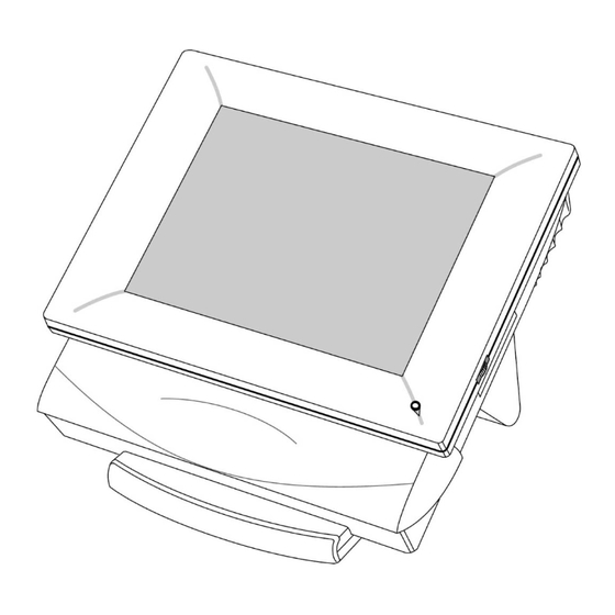
POS functionality like Cash Drawer interfaces all in a single system. The QT-7300 features desktop free standing and wall mounting for a wide variety of applications. An unique cable management device is also provided to trim the operation environment. In conformity to IPX1 standard, water- resistant system design is adopted. -
Page 4: Major Component
1-3. Major Component 1. Touchscreen: The QT7300 features a quick-response touchscreen for keyboardless operation. The standard touch adapted in this computer is 12.1" analog resistive type Fujitsu touchscreen. Its durability is 10 million touches in life. 2. Flat panel: To provide the best visual resolution and viewing angle, the standard display panel adapted in the QT7300 is 12.1"... -
Page 5: Specifications
1-4. Specifications Core System (Motherboard) • CPU: Celeron (566MHz) • System Chipset: Intel 440BX • BIOS: Award BIOS • System Memory: 1 x 168-pin DIMM socket, 64MB standard, upgradable to 256MB(buffered) • L2 Cache: Integrated in CPU • Real Time Clock : ST M48T86PC1 with built-in battery lasting 10 years •... - Page 6 2) The floppy disk drive, mouse and the P/C keyboard are designed for the engineers who are trained to use them for installation of the QT-7300 POS terminal and are not recommended to use at customer site as regular POS function in store hours. It may cause fail of the radiation regulation (ie.
-
Page 7: I/O Outlets
1-5. I/O Outlets The following diagram shows the I/O arrangement of the QT-7300. Bottom Panel 1) AC power switch 2) AC inlet 3) Ethernet 10/100 Base-T 4) Second VGA 5) Expansion slot 6) 3 X COM ports 7) 2X Cash Drawers... -
Page 8: Disassembly
2. DISASSEMBLY To open the case 1. Place the machine up side down. 2. Release the 2 screws of the case management shroud. Then, remove the case management shroud 4 screws of the lower case. The lower case Release the 2 screws. The case management shroud 3. - Page 9 5. Release the 4 screws of the Metal rear bracket. Then, remove the Metal rear bracket with the HDD unit. Release the 4 screws. The Metal rear bracket with the HDD unit 6. Remove the Riser card from themother board. Release the 4 screws of the Aluminum separator.
- Page 10 8. Release the 7 screws of the connector panel and release the 10 connector screws. Then, remove the Remove 10 connector screws. connector panel. Remove 2 screws. Remove 3 screws. Remove 2 screws. 9. Remove the connector from the Touchscreen con- troller.
- Page 11 11.Release the 9 screws of the Mother board. Then, remove the Mother board. — 9 —...
-
Page 12: Installation
3. INSTALLATION Unpacking The QT-7300 along with its accessories are packed in carton box. After unpacking the carton, place the system on a raised surface and carefully inspect the system for any damage that might have occurred during shipment. If there are damaged or missing parts, contact your dealer immediately. -
Page 13: System Installation
4. SYSTEM INSTALLATION This chapter describes the installation of the overall system of the QT-7300. See Chapter 4 for more details on the motherboard in detail. The QT-7300 has a Celeron/Pentium III based motherboard with a free PCI slot inside. It already builds in an Intel Celeron CPU, 64MB of DRAM and a 2.5"... -
Page 14: Hdd
QT-7300 four onboard serial ports. Since the touch screen system requires one dedicated serial port interface and COM1 is assigned for it, so that COM1 is not available for users. For the QT-7300, COM2 and COM4 are RS-232, selected by jumpers. Each serial port is with +5V/+24V and +12V/+24V power capabilities on pin 1 and pin 9, ready to accommodate a wide array of serial devices. -
Page 15: Cash Drawer
4-8. Cash Drawer The QT-7300 provides two Cash Drawer interface. Cash Drawers are assigned as one of I/O in this system and controlled by the Drawer port on the motherboard (SBC8360-4M). The pin assignment for the Cash Drawer connector is as follows. -
Page 16: Keyboard
4-11. External FDD The QT-7300 does not build in any floppy disk drive into the main system. Rather, it provides a FDD interface located at the side panel. An external FDD cable is provided to connect a standard 3.5" FDD to the system for system O/S and application software installation. -
Page 17: Expansion Slot
4-13. System O/S and Software Installation The QT-7300 is not equipped with any operating system. It builds in a 2.5" HDD as memory storage device. As both devices are built in the system chassis, to load Win98/Win98SE or Win2000 O/S or application software into the system, an external device is needed to act as a bridge. -
Page 18: Award Bios Setup
4-14. Award BIOS Setup Starting Award BIOS Setup As POST executes, the following appears Hit <DEL> if you want to run SETUP Press <Del> to run Award BIOS Setup. 4-14-1. Award BIOS Setup Main Menu When you enter the Award BIOS Setup Utility, the main menu will appear on the screen as follows. Use the arrow keys to move among the items and press <Enter>... - Page 19 The Award BIOS Setup options described in this section are selected by choosing the appropriate high-level icon from the Award BIOS Setup main menu selection screen. Default setting for the QT-7300 is described in < > next to each option. ( i.e. <AUTO> ) 4-14-2-1. Standard CMOS Setup <...
- Page 20 • Error Halt <All errors> The category determines whether the computer will stop if an error is detected during power up. • Memory The category is display-only which is determined by POST (Power On Self Test) of the BIOS. 4-14-2-2. BIOS Features Setup <...
- Page 21 • Typematic Rate Setting < Disabled > This determines the typematic rate of the keyboard. • Typematic Rate (Chars/Sec) < 6 > This option refers to the number of characters the keyboard can type per second. • Typematic Delay (msec) < 250 > This option sets the display time interval from the first to the second character when holding a key.
- Page 22 4-14-2-3. Chipset Features Setup < Screen shows all default setting > ROM PCI/ISA BIOS (2A69KA5C) CHIPSET FEATURES SETUP AWARD SOFTWARE, INC. SDRAM RAS-to-CAS Delay CPU Warning Temperature : Disabled : 35 °C/ 95 °F SDRAM RAS Precharge Time Current System1 Temp : 0 °C/ 32 °F SDRAM CAS Latency Time : Auto...
- Page 23 Video RAM Cacheable < Disabled > • Selecting Enabled allows caching of the Video BIOS ROM at C0000h to C7FFFh, resulting in better video performance. However, if any program writes to this memory area, a system error may result. • 8 bit I/O Recovery Time <...
- Page 24 4-14-2-4. Power Management Setup < Screen shows all default setting > ROM PCI/ISA BIOS (2A69KA5C) POWER MANAGEMENT SETUP AWARD SOFTWARE, INC. ACPI function : Disabled ** Reload Global Timer Events ** Power Management : User Define IRQ[3-7,9-15],NMI Disabled PM Control by APM : Yes Primary IDE 0 : Disabled...
- Page 25 • HDD Power Down < Disabled > After the selected period of drive inactivity (1 to 15 minute), the hard disk drive powers down while all other devices remain active. • Throttle Duty Cycle < 62.5% > When the system enters Doze mode, the CPU clock runs only part of the time. You must select the percent of time that the clock runs.
- Page 26 4-14-2-5. PCI / Plug and Play Setup < Screen shows all default setting > ROM PCI/ISA BIOS (2A69KA5C) PNP/PCI CONFIGRATION AWARD SOFTWARE, INC. PNP OS Installed : No Resources Controlled By : Auto Reset Configuration Data : Disabled Assign IRQ For USB : Enabled Onboard Ethernet BootROM : Disabled...
- Page 27 • IRQ 15 Assigned to < PCI/ISA PnP > When resources are controlled manually, assign each system interrupt as one of the following types, depending on the type of device using the interrupt: 1. Legacy ISA Devices compliant with the original PC AT bus specification, requiring a specific interrupt (such as IRQ4 for serial port 1).
- Page 28 4-14-2-6. Integrated Peripheral Setup < Screen shows all default setting > ROM PCI/ISA BIOS (2A69KA5C) INTEGRATED PERIPHERALS AWARD SOFTWARE, INC. IDE HDD Block Mode : Enabled UART Mode Select : Normal IDE Primary Master PIO : Auto IDE Primary Slave PIO : Auto IDE Secondary Master PIO : Auto...
- Page 29 PCI IDE < Enabled > • On-Chip Primary • On-Chip Secondary PCI IDE < Enabled > The integrated peripheral controller contain an IDE interface with support for two IDE channels. Select Enabled to active each channel separately. NOTE: Choosing Disabled for these options will automatically remove the IDE Primary Master/slave PIO and/or IDE Secondary Master/Slave PIO items on the menu.
-
Page 30: Watchdog Function
4-15. Watchdog Function The QT-7300 features a system protective device, watchdog timer which can generate a CPU reset when the system comes to a halt or failure. This function is to ensure the system's reliability during unattended operation. The trigger sources for the watchdog contain both temperature over range and system failure. The system failure may be caused by thunder, power glitch, radio interference, software bug or whatever reason. -
Page 31: Touch Screen
4-16. Touch screen The QT-7300 is equipped with a quick-response touch screen that enables keyboard-less operation. To use the touch screen, a related application program needs to be installed. This chapter provides all of the information to install and use the software of the Fujitsu touch screen systems for Windows98 SE and Windows 2000. - Page 32 4-16-2-1. Calibration 1) For Windows 98 SE and Windows 2000 (1) Insert Floppy disk into Floppy Disk Drive ("A:"). (2) Open "Explorer" <Click "Start", select" Programs" then select "Windows Explorer" >. (3) Click Floppy Disk Drive ("A:") in "All Folders" (4) Double Click "CALWIN(CALWIN.EXE)"...
-
Page 33: Ethernet Introduction
4-17. ETHERNET INTRODUCTION 4-17-1. Introduction The QT-7300 is equipped with high performance Plug & Play Ethernet interface which is fully compliant with IEEE802.3 standard, and consisting of RJ-45 connector . 4-17-2. Network Driver Installation under Windows98 Second Edition This describes in detail the important steps when installing the SBC8360-4M network drivers under Win98SE. - Page 34 4-17-3. Network Driver Installation under Windows 2000 This section describes in detail the important steps when installing the SBC8360-4M network drivers under Windows 2000. 1. Select the Start button at the bottom left corner of the screen then click on Settings. 2.
- Page 35 4-17-4. Setup and Diagnostic Test Following software are provided in the Ethernet RTL8139 Drivers (Disk 3) floppy disk for setup and test the Ethernet system. Run RSET8139.EXE, a list of options including "View Current Configuration", "Set Up New Configuration", "Run Diagnostic" and "Exit RSET8139" will appear. NOTE: You should run this software under dos mode.
-
Page 36: Circuit Explanations
5-1. Explanations of each block System Major Parts Refer to the following diagram to identify the major parts that make up the QT-7300. Plastic front cover: The plastic front cover is made of the ABS material. An indicating LED is on the right bottom side to indicate the power status. - Page 37 10. Power supply: The power supply adapted in this system is a super-slim 100W power which meets FCC/VDE Class B specification. 11. Motherboard: For the QT-7300 is Celeron/Pentium III based SBC8360-4M. It combine notebook technology to make up a compact and stable system.
- Page 38 7300. It is a compact and industrial-grade control board and is 100% PC compatible. missing number Hard disk: 2.5" notebook hard disk. Riser card: The QT-7300 provides one free slot expansion capability. Either one PCI device (half-size card) can be used at a given time. KB/Mouse/External FDD conversion card: Mylar insulator: An insulator is put under the power supply to ensure the power supply would not contact the metal compartment to cause any short circuit.
-
Page 39: Block Diagram
PISA Power Supply 100 W <To CDCC> Drawer 1 Drawer 2 CDCC PS/2 Multi I/O FDD/KB/MOUSE (2) QT-7300 system block diagram Celeron Procesor Host Bus (66/100 MHz) AGP Bus (66/100 MHz) North Bridge North Bridge C&T69030 82443BX 82443BX (66 MHz) -
Page 40: Jumper Setting
5-3. Jumper setting The default setting of the mother board for QT-7300 is as follows: SBC8360-4M Overview and Jumper switch CN17 CN11 CN13 JP13 JP11 JP12 CN27 JP10 BIOS CN29 JP17 CN30 JP4 JP7 PGA370 CN14 JP14 CN15 JP15 CN10... - Page 41 : Default / “X”: Don’t Care > Note: All specification and quality of the system are assured by Casio as the QT-7300, any local modification of the jumper setting by customer will not be applicable for Casio’s guarantee or warranty.
- Page 42 The corresponding jumper settings are shown below. <SBC8360-4M means the motherboard and MTIO means the Multi I/O board in the QT-7300. > COM1: COM1 is assigned for the touch screen system and is not available for end user in this system.
-
Page 43: Diagnostic Operation
Use the following softwares for checking each block. Mother board --------------------------------- AMI Diag.5.42 (available in the market) Customer display --------------------------- Diagnostic program built in the UNIT Drawer ----------------------------------------- drw.exe (available from Casio) Touch panel ---------------------------------- For DOS; medv10.com (Device Driver) caldos.com (Calibration program) - Page 44 In case of QT-7363D Loop back connector Display signal connector AC adaptor jack 1 Connect a loop back connector on Customer display stand unit. 2 Connect a testing customer display to Display signal connector. 3 Apply +24V DC to the AC adaptor jack. PRINTER Female HOST...
- Page 45 Precautions 1 For checking QT-7363D, use customer display stand unit. 2 Turn the power off before connecting the customer display. 3 After the check, be sure to set the DIP switch correctly. 4 Also check rotating mechanism of the customer display. Diagnose 1 Unscrew four screws and remove display panel.
- Page 46 All dots off All dots on A vertical line moves from right to left. 1 2 3 4 5 6 7 8 1 1 1 1 1 1 1 1 — 44 —...
-
Page 47: Drawer Test
5 Turn DIP switch 1~ 6 off. 1 2 3 4 5 6 7 8 0 0 0 0 0 0 1 0 6 Turn DIP switch 7 off. 1 2 3 4 5 6 7 8 0 0 0 0 0 0 0 0 After 1 second, display turns off. -
Page 48: Touch Panel Test
6-4. Touch panel test Set the driver then activate the calibration software. The following shows the software list and the test procedures. Software Files 1) For DOS * medv10.com Device Driver * caldos.com Calibration program 2) For Windows95 * fidmour.drv Device Driver * vfidmd.386 Device Driver... - Page 49 Calibration program In every touch, + turns in black red..1) For DOS 1 Start DOS 2 Insert Floppy disk into Floppy Disk Drive(“A:”) 3 Execute “CALDOS(CALDOS.EXE)” In case RS-232C PORT COM1 : CALDOS <Enter> RS-232C PORT COM2 : CALDOS C2 <Enter> 4 “Set calibration parameters”...
-
Page 50: Troubleshooting
7. TROUBLESHOOTING This portion of the service manual lists all possible malfunctions that may occur when operating the QT-7300 system. To assist you in fully analyzing the problem, the following table also includes an up-to-date list of symptoms and probable cause(s). In case you encounter problems or discover causes not included in this section, we highly recommend you to consult CASIO engineers. - Page 51 – Loose power connection on CN2 of the touchscreen control board. properly Pull out the power cable on CN2 then re-install it back. If symptoms persist, consult CASIO engineers. – Defective touchscreen control board Replace the touchscreen control board of the system.
-
Page 52: Data Sheet
8. DATA SHEET 8-1. Power Supply (100W) The power supply used in the QT-7300 is a 100W open frame power supply. The specifications and features of this special power supply are listed in the following sections. Specifications • High efficiency 100W output •... -
Page 53: Circuit Diagram
9. CIRCUIT DIAGRAM MODEL : QT-7300 (EX-963) CONTENTS 1. MOTHER BOARD SBC8360 (SBC8360-370)1/23 ..............52 2. MOTHER BOARD SBC8360 (443BX-A)2/23 ................. 53 3. MOTHER BOARD SBC8360 (443BX-B)3/23 ................. 54 4. MOTHER BOARD SBC8360 (DIMM0)4/23 ................55 5. MOTHER BOARD SBC8360 (PIIX4-A AND USB CONN)5/23 ..........56 6. - Page 54 9. PENTIUM MOTHER BOARD — 52 —...
- Page 55 MD63 MD62 MD61 MD60 MD59 MD58 MD57 MD56 MD55 MD54 MD53 MD52 MD51 MD50 MD49 MD48 MD31 MD30 MD29 MD28 MD27 MD26 MD25 MD24 MD23 MD22 MD21 MD20 MD19 MD18 MD17 MD16 HA31 HA30 HA29 HA28 HA27 HA26 HA25 HA24 HA23 HA22 HA21...
- Page 56 MD47 MD46 MD45 MD44 MD43 MD42 MD41 MD40 MD39 MD38 MD37 MD36 MD35 MD34 MD33 MD32 MD15 MD14 MD13 MD12 MD11 MD10 GD31 GD30 GD29 GD28 GD27 GD26 GD25 GD24 GD23 GD22 GD21 GD20 GD19 GD18 GD17 GD16 GD15 GD14 GD13 GD12 GD11...
- Page 57 — 55 —...
- Page 58 SA19 SA18 SA17 SA16 SA15 SA14 SA13 SA12 SA11 SA10 — 56 —...
- Page 59 LA23 LA22 LA21 LA20 LA19 LA18 LA17 SD15 SD14 SD13 SD12 SD11 SD10 — 57 —...
- Page 60 — 58 —...
- Page 61 — 59 —...
- Page 62 — 60 —...
- Page 63 — 61 —...
- Page 64 — 62 —...
- Page 65 — 63 —...
- Page 66 — 64 —...
- Page 67 — 65 —...
- Page 68 — 66 —...
- Page 69 — 67 —...
- Page 70 — 68 —...
- Page 71 — 69 —...
- Page 72 GD31 GD30 GD29 GD28 GD27 GD26 GD25 GD24 GD23 GD22 GD21 GD20 GD19 GD18 GD17 GD16 GD15 GD14 GD13 GD12 GD11 GD10 VAA5 VAA0 — 70 —...
- Page 73 — 71 —...
- Page 74 — 72 —...
- Page 75 AD10 AD11 AD12 AD13 AD14 AD15 AD16 AD17 AD18 AD19 AD20 AD21 AD22 AD23 AD24 — 73 —...
- Page 76 — 74 —...
- Page 77 — 75 —...
-
Page 78: Parts List
2. As for spare parts order and supply, refer to the “GUIDEBOOK for Spare Parts Supply”, published separately. 3. The numbers in item column corespond to the same numbers in drawing. 4. CASIO does not supply the spare parts without parts code. 5. Remarks Q'ty :... -
Page 79: Explode View
— 77 —... -
Page 80: Main Components
PARTS PRICE LIST QT-7300 Item Code No. Parts Name Specification Q Price Code R 1. Main components FRONT COVER 9487 0558 EDM-2313 (380/CASIO) 00-41500935 /with LED COVER 9487 0529 COVER/REAR EDM-2314 (380/CASIO) 00-41500955 1904 9027 CAP/DUST SPILL 6332000010 (345) 00-41500970... -
Page 81: Fdd/Mouse/Kb Pcb
Item Code No. Parts Name Specification Q Price Code R 9487 0560 SCREW S 3X6 BLACK 00-55100529 1904 9036 SCREW B3X5 00-55100671 1904 9037 SCREW 00-55101045 1904 9038 SCREW 3X25 00-55100535 1904 9080 SCREW S3X4(NI) 00-55101206 1906 0855 SCREW P2X6 00-55100030 1904 9041 SCREW P3X6SW... -
Page 82: Touch Panel Control Pcb
Item Code No. Parts Name Specification Q Price Code R N VGA DB15P(x2) 9487 0518 CONNECTOR HD15-SE-A 00-03204100 VGAA 1904 8955 CONNECTOR 8X2 (FEMALE) 00-03200860 1904 8957 HEADER 3PX2 00-04005030 1904 8959 PLUG/SHORT 00-03200900 1904 8951 SCREW P3X8 SW 00-55100130 SPACER SA55M3-10BS 00-35100045... -
Page 83: Lcd Convertor Pcb
Item Code No. Parts Name Specification Q Price Code R 1904 8929 CONNECTOR 53015-0710 00-04003048 1904 8928 CONNECTOR SLW15R-1C7 00-03200666 8. LCD convertor PCB 9487 0642 PCB/LCD CONVERTER EAL-0620B 00-00402460B 9487 0230 CONVERTER ASSY/LCD 20-010162-04 CHIP/CC MCH182FN104ZK 00-01104014 CHIP/TANTAL 4.7M 16V TCFGBIC475M8R 00-01400330 9487 0214 CONNECTOR... -
Page 84: Drawer
10. DRAWER DL-2773 (M Type) — 82 —... - Page 85 DL-2773 Item Code No. Parts name Specification Q'ty Price Code Rank 1 9487 0585 BOX 262Z-3110CC 2 1906 1309 CHASSIS/BOTTOM 264D-1101 3 5500 0619 ROLLER/DERLIN DR-19-B1 4 5500 0878 ROLLER/DERLIN DR-19-B2 5 1907 9682 WASHER SW-M6 6 1907 7150 NUT HN-M6 7 1908 1339 BRACKET/LOCK 37A-B150...
-
Page 86: Dl-2915 (M Type)
DL-2915 (M Type) — 84 —... - Page 87 Item Code No. Parts name Specification Q'ty Price code RANK 9487 0585 262Z-3110CC 1906 1309 CHASSIS/BOTTOM 264D-1101 5500 0619 ROLLER/DERLIN DR-19-B1 5500 0878 ROLLER/DERLIN DR-19-B2 1907 9682 WASHER SW-M6 1907 7150 HN-M6 1908 1339 BRACKET/LOCK 37A-B150 9487 0586 SOLENOID (with Micro switch) 182Z-S154Q 9487 0395 BRACKET/SHAFT GUIDE...
-
Page 88: Dl-3615 (L Type)
DL-3615 (L Type) — 86 —... - Page 89 PARTS PRICE LIST DL-3615 Item Code No. Parts Name Spec. Q'ty Price Code 1906 0670 Box sub ass'y ZD58110 1906 0671 Lock ass'y sith Switch ZD58140 1906 0672 P0.7 1906 0673 Label DL-3615 1906 0674 Cable ass'y ZD53644 1906 0675 Clamp CKN-05 1907 6275...
-
Page 90: Drawing
11. DRAWING — 88 —... - Page 91 Ver. 1 : Correction of page 78, 79 and 81. Ver. 2 : Correction of page 79. Ver. 3 : Correction of page 78. CASIO TECHNO CO.,LTD. Overseas Service Division Nishi-Shinjuku Kimuraya Bldg. 1F 5-25, Nishi-Shinjuku 7-Chome Shinjuku-ku, Tokyo 160-0023, Japan...
Need help?
Do you have a question about the QT-7300 and is the answer not in the manual?
Questions and answers