Table of Contents
Advertisement
Quick Links
Advertisement
Table of Contents

Subscribe to Our Youtube Channel
Related Manuals for Supero FatTwin F627R3-R72B+


Summary of Contents for Supero FatTwin F627R3-R72B+
- Page 1 UPER ® FatTwin F627R3-RTB+ F627R3-R72B+ User's Manual Revision 1.0c...
- Page 2 The information in this User’s Manual has been carefully reviewed and is believed to be accurate. The vendor assumes no responsibility for any inaccuracies that may be contained in this document, makes no commitment to update or to keep current the information in this manual, or to notify any person or organization of the updates.
-
Page 3: About This Manual
Preface Preface About This Manual This manual is written for professional system integrators and PC technicians. It provides information for the installation and use of the FatTwin F627R3-RTB+/R72B+. Installation and maintainance should be performed by experienced technicians only. The FatTwin™ F627R3-RTB+/R72B+ is a high-end server based on the SCF424AS-R1K28B 4U rackmount chassis and the dual processor X9DRFR serverboard. - Page 4 FatTwin F627R3-RTB+/R72B+ User's Manual Chapter 6: Advanced Chassis Setup Refer to Chapter 6 for detailed information on the SCF424AS-R1K28B server chassis. You should follow the procedures given in this chapter when installing, removing or reconfi guring SATA or peripheral drives and when replacing system power supply units and cooling fans.
- Page 5 FatTwin F627R3-RTB+/R72B+ User's Manual Notes...
-
Page 6: Table Of Contents
FatTwin F627R3-RTB+/R72B+ User's Manual Table of Contents Chapter 1 Introduction Overview ......................1-1 Serverboard Features ..................1-2 Processors ...................... 1-2 Memory ......................1-2 Serial ATA ....................... 1-3 SAS ......................... 1-3 PCI Expansion Slots ..................1-3 Onboard Controllers/Ports ................1-3 Graphics Controller ..................1-4 Nuvoton WPCM450 Controller ............... - Page 7 Table of Contents Cautions! ......................2-2 Choosing a Setup Location ................2-2 Rack Precautions .................... 2-2 Server Precautions ..................2-2 Rack Mounting Considerations ............... 2-3 Ambient Operating Temperature ..............2-3 Reduced Airfl ow ..................2-3 Mechanical Loading ................... 2-3 Circuit Overloading ..................2-3 Reliable Ground ..................
- Page 8 FatTwin F627R3-RTB+/R72B+ User's Manual Hot Swap Fan Warning ................. 4-16 Power Cable and AC Adapter ..............4-18 Chapter 5 Advanced Motherboard Setup Handling the Motherboard ................5-1 Precautions ..................... 5-1 Unpacking ....................... 5-1 Connecting Cables ..................5-2 Connecting Data Cables ................. 5-2 Control Panel Connectors and I/O Ports ............
- Page 9 Table of Contents Node Confi guration ..................6-10 Overview of the Node ................... 6-10 Removing and Installing the Backplane ............6-11 Removing the Backplane ................6-11 Installing the Backplane ................6-13 Adapter Card Replacement................6-14 6-10 Installing the Motherboard ................6-15 Compatible Motherboards ................6-15 Permanent and Optional Standoffs ...............
- Page 10 FatTwin F627R3-RTB+/R72B+ User's Manual Notes...
-
Page 11: Chapter 1 Introduction
Chapter 1: Introduction Chapter 1 Introduction Overview The FatTwin F627R3-RTB+/R72B+ is a high-end server comprised of two main subsystems: the SCF424AS-R1K28B 4U server chassis and the X9DRFR dual processor serverboard in four hot-swap nodes. Please refer to our web site for information on operating systems that have been certifi... -
Page 12: Serverboard Features
FatTwin F627R3-RTB+/R72B+ User's Manual Note: For your system to work properly, please follow the links below to download all necessary drivers/utilities and the user’s manual for your server. • Supermicro product manuals: http://www.supermicro.com/support/manuals/ • Product drivers and utilities: ftp://ftp.supermicro.com • Product safety information: http://super-dev/about/policies/safety_information.cfm •... -
Page 13: Serial Ata
Chapter 1: Introduction Serial ATA A Serial ATA controller is integrated into the C602 to provide up to a ten-port SATA subsystem, (two SATA 3 (6 Gb/s), four SATA 2 (3 Gb/s and four SCU SATA2 (3 Gb/s)) which is either RAID 0, 1, 5 and 10 (AHCI SATA2), RAID 0 and 1 (AHCI SATA3) or RAID 0 and 1 (SCU SATA2) supported. -
Page 14: Graphics Controller
FatTwin F627R3-RTB+/R72B+ User's Manual Graphics Controller The X9DRFR features an integrated Matrox G200eW Video Controller. Nuvoton WPCM450 Controller Note: The term "IPMI controller" and the term "BMC controller" can be used interchangeably in this section. The Nuvoton WPCM450R Controller, a Baseboard Management Controller (BMC), supports 2D/VGA-compatible Graphic Cores with PCI interface, creating multi-media virtualization via Keyboard/Video/Mouse Redirection (KVMR). -
Page 15: Power Supply
Chapter 1: Introduction • Multiple ADC inputs, Analog and Digital Video outputs • SPI Flash Host BIOS and fi rmware bootstrap program supported • Reduced Media Independent Interface (RMII) • OS (Operating System) Independency • Provides remote Hardware Health Monitoring via IPMI. Key features •... -
Page 16: Sas/Sata Subsystem
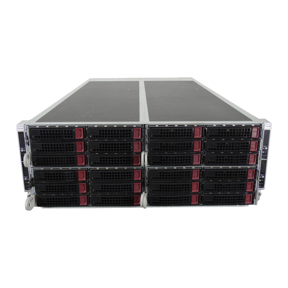
FatTwin F627R3-RTB+/R72B+ User's Manual SAS/SATA Subsystem The SCF424AS supports up to eight 3.5" hot-swap SAS/SATA drives in trays for each node for a total of thirty-two (32) drives. These drives are hot-swappable units and are connected to two backplanes (one for six and one for two HDD) that provides power and control. -
Page 17: Mounting Rails
Chapter 1: Introduction Mounting Rails The SCF424AS includes a set of rails, and can be placed in a rack for secure storage and use. To setup your rack, follow the step-by-step instructions included in this manual. Advanced Power Management Intel® Intelligent Power Node Manager (NM) The Intel®... - Page 18 FatTwin F627R3-RTB+/R72B+ User's Manual Figure 1-1. Intel C602 Chipset: System Block Diagram Note: This is a general block diagram and may not exactly repre- sent the features on your motherboard. See the previous pages for the actual specifi cations of your motherboard. This block diagram is intended for your reference only.
-
Page 19: Contacting Supermicro
Chapter 1: Introduction Contacting Supermicro Headquarters Address: Super Micro Computer, Inc. 980 Rock Ave. San Jose, CA 95131 U.S.A. Tel: +1 (408) 503-8000 Fax: +1 (408) 503-8008 Email: marketing@supermicro.com (General Information) support@supermicro.com (Technical Support) Website: www.supermicro.com Europe Address: Super Micro Computer B.V. Het Sterrenbeeld 28, 5215 ML 's-Hertogenbosch, The Netherlands Tel:... -
Page 20: Fat Twin: System Notes
FatTwin F627R3-RTB+/R72B+ User's Manual Fat Twin: System Notes As a Fat Twin confi guration, the FatTwin F627R3-RTB+/R72B+ is a unique server system. With eight system boards incorporated into a single chassis acting as eight separate nodes, there are several points you should keep in mind. Nodes Each of the four serverboards act as a separate node in the system. -
Page 21: Chapter 2 Server Installation
Chapter 2: Server Installation Chapter 2 Server Installation Overview This chapter provides a quick setup checklist to get your FatTwin F627R3-RTB+/R72B+ up and running. Following these steps in the order given should enable you to have the system operational within a minimum amount of time. This quick setup assumes that your system has come to you with the processors and memory preinstalled. -
Page 22: Cautions
FatTwin F627R3-RTB+/R72B+ User's Manual Cautions! Choosing a Setup Location • Leave enough clearance in front of the rack to enable you to open the front door completely (~25 inches) and approximately 30 inches of clearance in the back of the rack to allow for suffi cient airfl ow and ease in servicing. •... -
Page 23: Rack Mounting Considerations
Chapter 2: Server Installation Rack Mounting Considerations Warning! To prevent bodily injury when mounting or servicing this unit in a rack, you must take special precautions to ensure that the system remains stable. The following guidelines are provided to ensure your safety: •... -
Page 24: Reliable Ground
FatTwin F627R3-RTB+/R72B+ User's Manual Reliable Ground A reliable ground must be maintained at all times. To ensure this, the rack itself should be grounded. Particular attention should be given to power supply connections other than the direct connections to the branch circuit (i.e. the use of power strips, etc.). -
Page 25: Locking Tabs
Chapter 2: Server Installation Locking Tabs Each inner rail has a locking tab. This tab locks the chassis into place when installed and pushed fully into the rack. These tabs also lock the chassis in place when fully extended from the rack. This prevents the server from coming completely out of the rack when when the chassis is pulled out for servicing. -
Page 26: Installing The Rails On A Rack
FatTwin F627R3-RTB+/R72B+ User's Manual Installing the Rails on a Rack Installing the Rails 1. Adjust the length of both rails as described on the previous page. 2. Align the front section of the outer rail with the slots on the front post of the rack. -
Page 27: Chassis Installation
Chapter 2: Server Installation Chassis Installation Installing the Chassis into a Rack 1. Confi rm that the rails are correctly installed on the rack. 2. Align the bottom of the chassis with the bottom of the rails. 3. Insert the chassis into the rails, keeping the pressure even on both sides, pushing the chassis into the rack until it clicks into the locked position. -
Page 28: Checking The Serverboard Setup
FatTwin F627R3-RTB+/R72B+ User's Manual Checking the Serverboard Setup After you install the FatTwin F627R3-RTB+/R72B+ in the rack, you will need to open the unit to make sure the serverboard is properly installed and all the connections have been made. Accessing the inside of the System Before operating the server for the fi... -
Page 29: Checking The Drive Bay Setup
Chapter 2: Server Installation Checking the Drive Bay Setup Next, you should check to make sure the peripheral drives and the SATA drives have been properly installed and all connections have been made. Checking the Drives 1. All drives are accessable from the front and rear of the server. A hard drive can be installed and removed from the front of the chassis without removing the top chassis cover. - Page 30 FatTwin F627R3-RTB+/R72B+ User's Manual Notes 2-10...
-
Page 31: Chapter 3 System Interface
Chapter 3: System Interface Chapter 3 System Interface Overview There are several LEDs on the control panel and on the drive carriers to keep you constantly informed of the overall status of the system. SCF424AS models include four front panels on the handles of the chassis which control each of the systems. This chapter explains the meanings of all LED indicators and the appropriate response you may need to take. -
Page 32: Control Panel Buttons
FatTwin F627R3-RTB+/R72B+ User's Manual Control Panel Buttons • Power: The main power button on each of the four control panels is used to apply or remove power from the power supply to each of the four systems in the chassis. Turning off system power with this button removes the main power, but keeps standby power supplied to the system. -
Page 33: Control Panel Leds
Chapter 3: System Interface Control Panel LEDs The four control panels are located on the front handle of the SCF424AS chassis. Each control panel has two additional LEDs. These LEDs provide you with critical information related to different parts of the system. This section explains what each LED indicates when illuminated and any corrective action you may need to take. -
Page 34: Drive Carrier Leds
FatTwin F627R3-RTB+/R72B+ User's Manual Drive Carrier LEDs The chassis includes externally accessible SAS/SATA drives. Each drive carrier displays two status LEDs on the front of the carrier. LED Color State Status Activity LED Green Solid On SAS drive installed Green Blinking I/O activity Status LED... -
Page 35: Chapter 4 Standardized Warning Statements For Ac Systems
Chapter 4: Warning Statements for AC Systems Chapter 4 Standardized Warning Statements for AC Systems About Standardized Warning Statements The following statements are industry standard warnings, provided to warn the user of situations which have the potential for bodily injury. Should you have questions or experience difficulty, contact Supermicro's Technical Support department for assistance. - Page 36 FatTwin F627R3-RTB+/R72B+ User's Manual Warnung WICHTIGE SICHERHEITSHINWEISE Dieses Warnsymbol bedeutet Gefahr. Sie befi nden sich in einer Situation, die zu Verletzungen führen kann. Machen Sie sich vor der Arbeit mit Geräten mit den Gefahren elektrischer Schaltungen und den üblichen Verfahren zur Vorbeugung vor Unfällen vertraut.
- Page 37 Warning Statements for AC Systems ﺟﺴﺪﻳﺔ ﺍﺻﺎﺑﺔ ﺗﺘﺴﺒﺐ ﻓﻲ ﺣﺎﻟﺔ ﻳﻤﻜﻦ ﺃﻥ ﺍﻧﻚ ﻓﻲ ﺧﻄﺮ ﻳﻌﻨﻲ ﻫﺬﺍ ﺍﻟﺮﻣﺰ !ﺗﺤﺬﻳﺮ ﺍﻟﺪﻭﺍﺋﺮ ﺑﺎﻟﻤﺨﺎﻁﺮ ﺍﻟﻨﺎﺟﻤﺔ ﻋﻦ ﻦ ﻋﻠﻰ ﻋﻠﻢ ، ﻛ ﻣﻌﺪﺍﺕ ﺗﻌﻤﻞ ﻋﻠﻰ ﺃﻱ ﻗﺒﻞ ﺃﻥ ﺍﻟﻜﻬﺮﺑﺎﺋﻴﺔ ﺣﻮﺍﺩﺙ ﺃﻱ ﻭﻗﻮﻉ ﻤﻨﻊ ﻟ ﺍﻟﻮﻗﺎﺋﻴﺔ...
-
Page 38: Installation Instructions
FatTwin F627R3-RTB+/R72B+ User's Manual Installation Instructions Warning! Read the installation instructions before connecting the system to the power source. 警告 将此系统连接电源前,请先阅读安装说明。 警告 將系統與電源連接前,請先閱讀安裝說明。 Warnung Vor dem Anschließen des Systems an die Stromquelle die Installationsanweisungen lesen. ¡Advertencia! Lea las instrucciones de instalación antes de conectar el sistema a la red de alimentación. -
Page 39: Circuit Breaker
Chapter 4: Warning Statements for AC Systems Circuit Breaker Warning! This product relies on the building's installation for short-circuit (overcurrent) protection. Ensure that the protective device is rated not greater than: 250 V, 20 A. 警告 此产品的短路(过载电流)保护由建筑物的供电系统提供,确保短路保护设备的额定电 流不大于250V,20A。 警告 此產品的短路(過載電流)保護由建築物的供電系統提供,確保短路保護設備的額定電 流不大於250V,20A。... -
Page 40: Power Disconnection Warning
FatTwin F627R3-RTB+/R72B+ User's Manual ﻓﻲ ﺍﻟﺘﻲ ﺗﻢ ﺗﺜﺒﻴﺘﻬﺎ ﻣﻦ ﺍﻟﺪﻭﺍﺋﺮﺍﻟﻘﺼﻴﺮﺓ ﺍﻟﺤﻤﺎﻳﺔ ﻣﻌﺪﺍﺕ ﻳﻌﺘﻤﺪ ﻋﻠﻰ ﻫﺬﺍ ﺍﻟﻤﻨﺘﺞ ﺍﻟﻤﺒﻨﻰ ﺃﻛﺜﺮ ﻣﻦ ﻟﻴﺲ ﻮﻗﺎﺋﻲ ﺍﻟ ﺍﻟﺠﻬﺎﺯ ﺗﻘﻴﻴﻢ ﺃﻥ ﺗﺄﻛﺪ ﻣﻦ 20A, 250V Waarschuwing Dit product is afhankelijk van de kortsluitbeveiliging (overspanning) van uw electrische installatie. - Page 41 Chapter 4: Warning Statements for AC Systems Warnung Das System muss von allen Quellen der Energie und vom Netzanschlusskabel getrennt sein, das von den Spg.Versorgungsteilmodulen entfernt wird, bevor es auf den Chassisinnenraum zurückgreift, um Systemsbestandteile anzubringen oder zu entfernen. ¡Advertencia! El sistema debe ser disconnected de todas las fuentes de energía y del cable eléctrico quitado de los módulos de fuente de alimentación antes de tener acceso el interior del chasis para instalar o para quitar componentes de sistema.
-
Page 42: Equipment Installation
FatTwin F627R3-RTB+/R72B+ User's Manual Equipment Installation Warning! Only trained and qualifi ed personnel should be allowed to install, replace, or service this equipment. 警告 只有经过培训且具有资格的人员才能进行此设备的安装、更换和维修。 警告 只有經過受訓且具資格人員才可安裝、更換與維修此設備。 Warnung Das Installieren, Ersetzen oder Bedienen dieser Ausrüstung sollte nur geschultem, qualifi ziertem Personal gestattet werden. ¡Advertencia! Solamente el personal califi... -
Page 43: Restricted Area
Chapter 4: Warning Statements for AC Systems Waarschuwing Deze apparatuur mag alleen worden geïnstalleerd, vervangen of hersteld door geschoold en gekwalifi ceerd personeel. Restricted Area Warning! This unit is intended for installation in restricted access areas. A restricted access area can be accessed only through the use of a special tool, lock and key, or other means of security. -
Page 44: Battery Handling
FatTwin F627R3-RTB+/R72B+ User's Manual אזור עם גישה מוגבלת !אזהרה יש להתקין את היחידה באזורים שיש בהם הגבלת גישה. הגישה ניתנת בעזרת .('כלי אבטחה בלבד )מפתח, מנעול וכד ﻣﺤﻈﻮﺭﺓ ﻣﻨﺎﻁﻖ ﻟﺘﺮﻛﻴﺒﻬﺎ ﻓﻲ ﻫﺬﻩ ﺍﻟﻮﺣﺪﺓ ﺗﺨﺼﻴﺺ ﺗﻢ ،ﺃﺩﺍﺓ ﺧﺎﺻﺔ ﻣﻦ ﺧﻼﻝ ﺍﺳﺘﺨﺪﺍﻡ ﻓﻘﻂ... - Page 45 Chapter 4: Warning Statements for AC Systems Warnung Bei Einsetzen einer falschen Batterie besteht Explosionsgefahr. Ersetzen Sie die Batterie nur durch den gleichen oder vom Hersteller empfohlenen Batterietyp. Entsorgen Sie die benutzten Batterien nach den Anweisungen des Herstellers. Attention Danger d'explosion si la pile n'est pas remplacée correctement. Ne la remplacer que par une pile de type semblable ou équivalent, recommandée par le fabricant.
-
Page 46: Redundant Power Supplies
FatTwin F627R3-RTB+/R72B+ User's Manual Redundant Power Supplies Warning! This unit might have more than one power supply connection. All connections must be removed to de-energize the unit. 警告 此部件连接的电源可能不止一个,必须将所有电源断开才能停止给该部件供电。 警告 此裝置連接的電源可能不只一個,必須切斷所有電源才能停止對該裝置的供電。 Warnung Dieses Gerät kann mehr als eine Stromzufuhr haben. Um sicherzustellen, dass der Einheit kein trom zugeführt wird, müssen alle Verbindungen entfernt werden. -
Page 47: Backplane Voltage
Chapter 4: Warning Statements for AC Systems ﺍﻣﺪﺍﺩ ﺍﻟﻄﺎﻗﺔ ﺑﻮﺣﺪﺍﺕ ﻋﺪﺓ ﺍﺗﺼﺎﻻﺕ ﺠﻬﺎﺯ ﺍﻟ ﻳﻜﻮﻥ ﻟﻬﺬﺍ ﻗﺪ ﺍﻟﻜﻬﺮﺑﺎء ﻋﻦ ﻮﺣﺪﺓ ﺍﻟ ﻟﻌﺰﻝ ﻛﺎﻓﺔ ﺍﻻﺗﺼﺎﻻﺕ ﻳﺠﺐ ﺇﺯﺍﻟﺔ Waarschuwing Deze eenheid kan meer dan één stroomtoevoeraansluiting bevatten. Alle aansluitingen dienen verwijderd te worden om het apparaat stroomloos te maken. Backplane Voltage Warning! Hazardous voltage or energy is present on the backplane when the system is... -
Page 48: Comply With Local And National Electrical Codes
FatTwin F627R3-RTB+/R72B+ User's Manual Attention Lorsque le système est en fonctionnement, des tensions électriques circulent sur le fond de panier. Prendre des précautions lors de la maintenance. מתח בפנל האחורי !הרה אז קיימת סכנת מתח בפנל האחורי בזמן תפעול המערכת. יש להיזהר במהלך .העבודה... -
Page 49: Product Disposal
Chapter 4: Warning Statements for AC Systems ¡Advertencia! La instalacion del equipo debe cumplir con las normas de electricidad locales y nacionales.Attention L'équipement doit être installé conformément aux normes électriques nationales et locales. תיאום חוקי החשמל הארצי !אזהרה הציוד חייבת להיות תואמת לחוקי החשמל המקומיים והארציים התקנת... -
Page 50: Hot Swap Fan Warning
FatTwin F627R3-RTB+/R72B+ User's Manual Warnung Die Entsorgung dieses Produkts sollte gemäß allen Bestimmungen und Gesetzen des Landes erfolgen. ¡Advertencia! Al deshacerse por completo de este producto debe seguir todas las leyes y reglamentos nacionales. Attention La mise au rebut ou le recyclage de ce produit sont généralement soumis à des lois et/ou directives de respect de l'environnement. - Page 51 Chapter 4: Warning Statements for AC Systems 当您从机架移除风扇装置,风扇可能仍在转动。小心不要将手指、螺丝起子和其他 物品太靠近风扇 警告 當您從機架移除風扇裝置,風扇可能仍在轉動。小心不要將手指、螺絲起子和其他 物品太靠近風扇。 Warnung Die Lüfter drehen sich u. U. noch, wenn die Lüfterbaugruppe aus dem Chassis genommen wird. Halten Sie Finger, Schraubendreher und andere Gegenstände von den Öffnungen des Lüftergehäuses entfernt. ¡Advertencia! Los ventiladores podran dar vuelta cuando usted quite ell montaje del ventilador del chasis.
-
Page 52: Power Cable And Ac Adapter
FatTwin F627R3-RTB+/R72B+ User's Manual Waarschuwing Het is mogelijk dat de ventilator nog draait tijdens het verwijderen van het ventilatorsamenstel uit het chassis. Houd uw vingers, schroevendraaiers en eventuele andere voorwerpen uit de buurt van de openingen in de ventilatorbehuizing. Power Cable and AC Adapter Warning! When installing the product, use the provided or designated connection cables, power cables and AC adaptors. - Page 53 Chapter 4: Warning Statements for AC Systems ¡Advertencia! Al instalar el producto, utilice los cables de conexión previstos o designados, los cables y adaptadores de CA. La utilización de otros cables y adaptadores podría ocasionar un mal funcionamiento o un incendio. Aparatos Eléctricos y la Ley de Seguridad del Material prohíbe el uso de UL o CSA cables certifi...
- Page 54 FatTwin F627R3-RTB+/R72B+ User's Manual Waarschuwing Bij het installeren van het product, gebruik de meegeleverde of aangewezen kabels, stroomkabels en adapters. Het gebruik van andere kabels en adapters kan leiden tot een storing of een brand. Elektrisch apparaat en veiligheidsinformatiebladen wet verbiedt het gebruik van UL of CSA gecertifi...
-
Page 55: Chapter 5 Advanced Motherboard Setup
Chapter 5: Advanced Motherboard Setup Chapter 5 Advanced Motherboard Setup This chapter covers the steps required to install the X9DRFR motherboard into the chassis, connect the data and power cables and install add-on cards. All motherboard jumpers and connections are also described. A layout and quick reference chart are included in this chapter for your reference. -
Page 56: Connecting Cables
FatTwin F627R3-RTB+/R72B+ User's Manual Connecting Cables Now that the processors are installed, the next step is to connect the cables to the serverboard. Connecting Data Cables The cables used to transfer data from the peripheral devices have been carefully routed in preconfi gured systems to prevent them from blocking the fl ow of cooling air that moves through the system from front to back. -
Page 57: Connecting The Control Panel
Chapter 5: Advanced Motherboard Setup Back Panel I/O Port Locations and Defi nitions USB Port 1 USB Port 2 VGA Port Gigabit LAN 1 Gigabit LAN 2 IPMI LAN Connecting the Control Panel JF1 contains header pins for various front control panel connectors. See Figure 5-1 for the pin locations of the various front control panel buttons and LED indicators. -
Page 58: Processor And Heatsink Installation
FatTwin F627R3-RTB+/R72B+ User's Manual Processor and Heatsink Installation Warning! When handling the processor package, avoid placing direct pressure on the label area. Warning! If you buy a CPU separately, make sure that you use an Intel-certifi ed multi- directional heatsink only. Note: Always connect the power cord last, and always remove it before adding, removing or changing any hardware components. - Page 59 Chapter 5: Advanced Motherboard Setup 2. Press the second load lever labeled 'Close 1st' to release the load plate that covers the CPU socket from its locking position. Press down on Load the Pull lever away Lever labeled 'Close 1st' from the socket 3.
- Page 60 FatTwin F627R3-RTB+/R72B+ User's Manual 5. Use your thumb and index fi nger to hold the CPU on its edges. Align the CPU keys, which are semi-circle cutouts, against the socket keys. Socket Keys CPU Keys 6. Once they are aligned, carefully lower the CPU straight down into the socket. (Do not drop the CPU on the socket.
- Page 61 Chapter 5: Advanced Motherboard Setup 7. With the CPU inside the socket, inspect the four corners of the CPU to make sure that the CPU is properly installed. 8. Close the load plate with the CPU inside the socket. Lock the lever labeled 'Close 1st' fi...
-
Page 62: Installing A Passive Cpu Heatsink
FatTwin F627R3-RTB+/R72B+ User's Manual Installing a Passive CPU Heatsink 1. Do not apply any thermal grease to the heatsink or the CPU die -- the required amount has already been applied. 2. Place the heatsink on top of the CPU so that the four mounting holes are aligned with those on the Motherboard's and the Heatsink Bracket underneath. -
Page 63: Removing The Heatsink
Chapter 5: Advanced Motherboard Setup Removing the Heatsink Caution: We do not recommend that the CPU or the heatsink be removed. However, if you do need to uninstall the heatsink, please follow the instructions below to avoid damaging the CPU or the CPU socket. 1. -
Page 64: Installing Memory
FatTwin F627R3-RTB+/R72B+ User's Manual Installing Memory Caution: exercise extreme care when installing or removing DIMM modules to prevent any possible damage. Installing Memory 1. Insert the desired number of DIMMs into the memory slots, starting with P1- DIMM #1A. (For best performance, please use the memory modules of the same type and speed in the same bank.) 2. -
Page 65: Removing Memory Modules
Chapter 5: Advanced Motherboard Setup Removing Memory Modules Press both notches on the ends of the DIMM module to unlock it. Once the DIMM module is loosened, remove it from the memory slot. Memory Support The X9DRFR motherboard supports up to 512 GB of 240-pin Registered (RDIMM)/ Load Reduced (LRDIMM) ECC or up to 128 GB of Unbuffered (UDIMM) ECC/ Non-ECC DDR3-1600/1333/1066/800 MHz 4- channel memory in sixteen (16) DIMM slots. -
Page 66: Installing Udimm (Ecc/Non-Ecc) Memory
FatTwin F627R3-RTB+/R72B+ User's Manual Installing UDIMM (ECC/Non-ECC) Memory Intel E5-2600 Series Processor UDIMM Memory Support Ranks Memory Capacity Speed (MT/s) and Voltage Validated by Slot Per DIMM per Channel (SPC) and DIMM Per Channel DIMM (DPC) & Data (See the Note below) 1 Slot Per 2 Slots Per Channel Width... -
Page 67: Installing Rdimm (Ecc) Memory
Chapter 5: Advanced Motherboard Setup Installing RDIMM (ECC) Memory Intel E5-2600 Series Processor RDIMM Memory Support Ranks Memory Capacity Speed (MT/s) and Voltage Validated by Slot Per DIMM per Channel (SPC) and DIMM Per Channel DIMM (DPC) & Data (See the Note Below) 1 Slot Per 2 Slots Per Channel Width... -
Page 68: Motherboard Details
FatTwin F627R3-RTB+/R72B+ User's Manual Motherboard Details Figure 5-4. X9DRFR Motherboard Layout (not drawn to scale) VGA1 USB1 IPMI LAN2 LAN1 _LAN LEM1 JBT1 CTRL JBAT1 JI2C1 JPG1 I-SATA3 JI2C2 S-SATA2 S-SATA3 JPW2 X9DRFR Rev. 2.00 CPU1 JITP0 CPU2 5-14... - Page 69 Chapter 5: Advanced Motherboard Setup Notes: 1. For the latest CPU/Memory updates, please refer to our website at http:// www.supermicro.com/products/motherboard/ for details. 2. Use only the correct type of onboard CMOS battery as specifi ed by the manufacturer. Do not install the onboard battery upside down to avoid possible explosion.
- Page 70 FatTwin F627R3-RTB+/R72B+ User's Manual Connector Description FAN#1-3, FANA CPU/System (4-Pin) Fan Headers PCI-E 3.0 x16 Slot (Available when CPU1 is installed) PCI-E x8 Micro Low-Profi le (MLP) Riser Card Slot w/support of 2 LANs or 10Gb LAN or Infi niBand Connections (Available when CPU1 is installed) PCI-E 3.0 x 8 Slot for SMC-Proprietary Add-On Card (Available when CPU1 is installed) (See Note 1)
-
Page 71: Connector Defi Nitions
Chapter 5: Advanced Motherboard Setup Connector Defi nitions Power Button Power Button Pin Defi nitions (JF1) The Power Button connection is located Pin# Defi nition on pins 1 and 2 of JF1. Momentarily Signal contacting both pins will power on/off Ground the system. - Page 72 FatTwin F627R3-RTB+/R72B+ User's Manual Front Panel Power On LED FP PWR On LED Pin Defi nitions (JF1) Connect an LED Cable to pins 9 and Pin# Defi nition 10 of JF1 to indicate if onboard power Front Panel PWR LED is on.
- Page 73 Chapter 5: Advanced Motherboard Setup Power Management Bus PMBUS Button Pin Defi nitions (JF1) The Power Management Bus header is Pin# Defi nition located on pins 19 and 20 of JF1. Refer PMBUS Clock to the table on the right for pin defi nitions. PMBUS Data Ethernet LAN Ports Two Gigabit Ethernet ports (LAN1,...
- Page 74 FatTwin F627R3-RTB+/R72B+ User's Manual Power Supply The power supply cables are wired on the motherboard. Please connect the onboard power cable to the SMC-Proprietary Adaptor (PN# BPN-ADP-F418) that is installed in the chassis to provide power to the system. Fan Headers Fan Header (Fan 1~3, Fan A) Pin Defi...
- Page 75 Chapter 5: Advanced Motherboard Setup IPMB I C SMB SMB Header (JIPMB1) Pin Defi nitions A System Management Bus header for Pin# Defi nition IPMI 2.0 is located at JIPMB1. Connect Data the appropriate cable here to use the Ground IPMB I C connection on your system.
-
Page 76: Jumper Settings
FatTwin F627R3-RTB+/R72B+ User's Manual Jumper Settings Connector Pins Explanation of Jumpers To modify the operation of the motherboard, Jumper jumpers can be used to choose between optional settings. Jumpers create shorts between two pins to change the function Setting of the connector. Pin 1 is identifi ed with a square solder pad on the printed circuit board. - Page 77 Chapter 5: Advanced Motherboard Setup GLAN Enable/Disable GLAN Enable Jumper Settings JPL1 enables or disables the LAN Port1/ Jumper Setting Defi nition LAN Port2 on the motherboard. See the Enabled (default) table on the right for jumper settings. Disabled The default setting is Enabled. Watch Dog Enable/Disable Watch Dog (JWD1) Jumper Settings...
-
Page 78: Onboard Indicators
FatTwin F627R3-RTB+/R72B+ User's Manual BMC Reset BMC Reset Jumper Settings Close the pins of JBRST1 to reset BMC Jumper Setting Defi nition settings. See the table on the right for BMC Reset jumper settings. Normal (Default) Onboard Indicators GLAN LEDs GLAN LED Link Speed Activity... - Page 79 Chapter 5: Advanced Motherboard Setup Onboard Power LED Onboard PWR LED Indicator (LE1) LED Settings An Onboard Power LED is located at LED Color Status LE1 on the motherboard. When this System Off (PWR LED is on, the system is on. Be sure cable not connected) to turn off the system and unplug the Green...
-
Page 80: 5-10 Serial Ata Connections
FatTwin F627R3-RTB+/R72B+ User's Manual 5-10 Serial ATA Connections Serial ATA Ports There are ten Serial_ATA ports on the motherboard. I-SATA ports 0/1 support SATA 3.0 connections. I-SATA 2-5 from the PCH chip, and S-SATA 0/1/2/3 from the SCU chip are SATA 2.0 connectors. These ports provide serial-link signal connections, which are faster than the connections of Parallel ATA. -
Page 81: 5-11 Installing Drivers
Chapter 5: Advanced Motherboard Setup 5-11 Installing Drivers The Supermicro ftp site contains drivers and utilities for your system at ftp://ftp. supermicro.com. Some of these must be installed, such as the chipset driver. After accessing the ftp site, go into the CDR_Images directory and locate the ISO fi... - Page 82 SuperDoctor III, as the SuperDoctor III settings override the BIOS settings. To set the BIOS temperature threshold settings again, you would fi rst need to uninstall SuperDoctor III. Figure 5-7. Supero Doctor III Interface Display Screen (Health Information) 5-28...
-
Page 83: Superdoctor Iii
Chapter 5: Advanced Motherboard Setup Figure 5-8. Supero Doctor III Interface Display Screen (Remote Control) Note: The SuperDoctor III program and User’s Manual can be downloaded from the Supermicro web site at http://www.supermicro.com/products/accessories/software/ SuperDoctorIII.cfm.For Linux, we recommend that you use the SuperoDoctor II application instead. -
Page 84: 5-12 Serverboard Battery
FatTwin F627R3-RTB+/R72B+ User's Manual 5-12 Serverboard Battery Caution: There is a danger of explosion if the onboard battery is installed upside down, which will reverse its polarites (see Figure 5-9). This battery must be replaced only with the same or an equivalent type recommended by the manufacturer (CR2032). -
Page 85: Chapter 6 Advanced Chassis Setup
Chapter 6: Advanced Chassis Setup Chapter 6 Advanced Chassis Setup This chapter covers the steps required to install components and perform maintenance on the SCF424AS-R1K28B chassis. For component installation, follow the steps in the order given to eliminate the most common problems encountered. If some steps are unnecessary, skip ahead to the step that follows. -
Page 86: Control Panel
FatTwin F627R3-RTB+/R72B+ User's Manual Figure 6-1. Front and Rear Chassis Views Control Panel Control Panel SAS/SATA Drives (48) VGA Port IPMI LAN Port USB Ports Ethernet Ports Control Panel The control panel for each node is located on the front of the chassis. The LEDs inform you of system status. -
Page 87: Removing The Power Cord
Chapter 6: Advanced Chassis Setup Removing the Power Cord Before performing any setup or maintenance on the chassis, use the following procedure to ensure that power has been removed disconnected from the system. Removing the Power Cord 1. Use the operating system to power down the node, following the on-screen prompts. -
Page 88: Installing And Removing Hard Drives
FatTwin F627R3-RTB+/R72B+ User's Manual Installing and Removing Hard Drives The SCF424AS chassis contains individual motherboards in separate 2U nodes. Each motherboard node controls the hard drives contained within that node. Note that if a motherboard node is pulled out of the chassis, the hard drives associated with that node will power down as well. - Page 89 Chapter 6: Advanced Chassis Setup Removing Hard Drive Carriers from a Node 1. Press the release button on the drive carrier. This extends the drive bay handle. 2. Use the handle to pull the drive carrier out of the node. Figure 6-3: Removing a 3.5"...
- Page 90 FatTwin F627R3-RTB+/R72B+ User's Manual Figure 6-4: Removing a 3.5" Hard Drive Carrier from the Rear of the Node...
- Page 91 Chapter 6: Advanced Chassis Setup The drives are mounted in drive carriers to simplify their installation and removal from the chassis. These carriers also help promote proper airfl ow for the drive bays. Removing the Dummy Drive from the 3.5" Drive Carrier 1.
- Page 92 FatTwin F627R3-RTB+/R72B+ User's Manual Installing a 3.5" Hard Drive into the Drive Carrier 1. Place the hard drive carrier on a fl at surface. 2. Insert the hard drive into the carrier with the printed circuit board side facing downward and so that the mounting holes in the drive align with those in the drive carrier.
-
Page 93: Removing The Node Cover
Chapter 6: Advanced Chassis Setup Removing the Node Cover Each node has a removable cover which will permit access to the nodes components. Removing the Node Cover 1. Remove the motherboard node completely from the chassis and place it on a fl... -
Page 94: Node Confi Guration
FatTwin F627R3-RTB+/R72B+ User's Manual Node Confi guration Overview of the Node Figure 6-8: Front and Rear of the SCF424AS Motherboard Node (Your node may differ from the one shown in this illustration) Front of the Node Rear of the Node SCF424AS-R1K28BP Front of Node Rear of Node... -
Page 95: Removing And Installing The Backplane
Chapter 6: Advanced Chassis Setup Removing and Installing the Backplane The SCF424AS chassis backplane is located behind the hard drives and in front of the front system fans in each motherboard node. Although backplane failure rarely occurs, in the event of a backplane failure, follow the instructions below. Removing the Backplane Removing the Backplane from the Chassis 1. - Page 96 FatTwin F627R3-RTB+/R72B+ User's Manual 4. Remove the four screws securing the backplane to the node. 5. Lift the backplane up and out of the chassis (Figure 6-10). Figure 6-10: Removing the Backplane from the Chassis (Your node and backplane may differ from the one shown in this illustration) 6-12...
-
Page 97: Installing The Backplane
Chapter 6: Advanced Chassis Setup Installing the Backplane Installing the Backplane into the Chassis 1. Ensure that all of the hard drive carriers have been removed from the bays in the front of the node (see Section 6-5 Installing and Removing Hard Drives). 2. -
Page 98: Adapter Card Replacement
FatTwin F627R3-RTB+/R72B+ User's Manual Adapter Card Replacement Each of the motherboard nodes for the F627R3-R72B+ server includes an adapter card, which connects it to the chassis. In the unlikely event of a failure of the adapter card, replacement is simple and requires only a Phillips head screwdriver. Changing the Adapter Card 1. -
Page 99: 6-10 Installing The Motherboard
Chapter 6: Advanced Chassis Setup 6-10 Installing the Motherboard Compatible Motherboards For the most up-to-date information on compatible motherboards and other parts, visit the Supermicro Web site at www.supermicro.com. Permanent and Optional Standoffs Standoffs prevent short circuits by creating space between the motherboard and the fl... - Page 100 FatTwin F627R3-RTB+/R72B+ User's Manual 7. Connect the cables between the motherboard, backplane, chassis, front panel, and power supply, as needed. The fans may be temporarily removed to allow access to the backplane ports. 8. Replace the expansion card bracket and secure the bracket with a screw. 9.
-
Page 101: 6-11 Installing Expansion Cards
Chapter 6: Advanced Chassis Setup 6-11 Installing Expansion Cards PCIE Slot Setup The nodes of some SCF424AS chassis models support expansion cards and or Micro LP cards. To install low-profi le expansion cards and Micro LP expansion cards, follow the instructions on the following pages. Figure 6-14: PCIE Slot Shield Confi... -
Page 102: Scf424 Pcie Slot Confi Gurations
FatTwin F627R3-RTB+/R72B+ User's Manual SCF424 PCIE Slot Confi gurations Some SCF424AS chassis models support one or more expansion cards in the PCIE slots of each node, Refer to the tables below to determine the PCIE slot confi guration for your particular chassis. SCF424AS-R1K28BP Front of Node Rear of Node... -
Page 103: Installing A Rear Micro Lp Expansion Card
Chapter 6: Advanced Chassis Setup Installing a Rear Micro LP Expansion Card Installing the Micro LP Expansion Card into the Node 1. Power down the system and remove the power cord from the rear of the power supply as described in Section 6-3. Remove the node from the chassis as described in Section 6-4 and place the node on a fl... -
Page 104: Installing A Front Low-Profi Le Expansion Card
FatTwin F627R3-RTB+/R72B+ User's Manual Installing a Front Low-Profi le Expansion Card Each motherboard node supports one low-profi le expansion card. Installing a Front Expansion Card into a Node 1. Power down the system and remove the power cord from the rear of the power supply as described in Section 6-3. - Page 105 Chapter 6: Advanced Chassis Setup 5. Lift the riser card bracket up and out of the chassis. Figure 6-19: Removing the Riser Card Bracket from the Node 6. Assemble the riser card as illustrated below, securing the riser card to the riser card bracket with the two screws provided.
-
Page 106: 6-12 Installing The Air Shroud
FatTwin F627R3-RTB+/R72B+ User's Manual 6-12 Installing the Air Shroud Air shrouds concentrate airfl ow to maximize fan effi ciency. The SCF424 chassis requires an air shroud in each motherboard node. Installing the Air Shroud 1. Power down the system and remove the power cord from the rear of the power supply as described in Section 6-3. -
Page 107: 6-13 Checking The Airfl Ow
Chapter 6: Advanced Chassis Setup 6-13 Checking the Airfl ow Checking Airfl ow 1. Make sure there are no objects to obstruct airfl ow in and out of the server. In addition, if you are using a front bezel, make sure the bezel's fi lter is replaced periodically. -
Page 108: 6-14 Replacing System Fans
FatTwin F627R3-RTB+/R72B+ User's Manual 6-14 Replacing System Fans System fans provide cooling for each node. Front I/O nodes have rear external fans and rear I/O nodes have front internal fans. These fans circulate air through the node as a means of lowering the internal temperature. The SCF424AS system fans are easily removed from the fan tray. - Page 109 Chapter 6: Advanced Chassis Setup 6. Lift the fan housing up and out of the chassis. 7. Simultaneously squeeze both sets of release tabs on each side of the fan housing. This will release the cover plate of the housing which holds the fans inside the housing.
-
Page 110: 6-15 Replacing The Power Supply
FatTwin F627R3-RTB+/R72B+ User's Manual 6-15 Replacing the Power Supply The SCF424AS chassis includes a 1280 Watt power supply. This power supply is auto-switching capable. This enables it to automatically sense and operate at a 100v to 240v input voltage. An amber light will be illuminated on the power supply when the power is off. -
Page 111: 6-16 Power Distributor Board Replacement
Chapter 6: Advanced Chassis Setup 6-16 Power Distributor Board Replacement In the unlikely event of a power adapter board failure, replacement is simple and requires only a Phillips head screwdriver. Changing the Power Adapter Board 1. Power down the system and remove the power cord from the rear of the power supply as described in Section 6-3. - Page 112 FatTwin F627R3-RTB+/R72B+ User's Manual Notes 6-28...
-
Page 113: Chapter 7 Bios
Chapter 7: BIOS Chapter 7 BIOS Introduction This chapter describes the AMI BIOS Setup Utility for the X9DRFR serverboard. The 128 MB AMI BIOS® is stored in a Flash EEPROM and can be easily updated. This chapter describes the basic navigation of the AMI BIOS Setup Utility setup screens. Starting BIOS Setup Utility To enter the AMI BIOS Setup Utility screens, press the <Delete>... -
Page 114: Starting The Setup Utility
FatTwin F627R3-RTB+/R72B+ FatTwin Starting the Setup Utility Normally, the only visible Power-On Self-Test (POST) routine is the memory test. As the memory is being tested, press the <Delete> key to enter the main menu of the AMI BIOS Setup utility. From the main menu, you can access the other setup screens. - Page 115 Chapter 7: BIOS The AMI BIOS Main menu displays the following information: System Date/System Time Use this option to change the system time and date. Highlight System Time or System Date using the arrow keys. Enter new values through the keyboard and press <Enter>.
-
Page 116: Advanced Settings Menu
FatTwin F627R3-RTB+/R72B+ FatTwin Advanced Settings Menu Select the Advanced tab to access the following submenu items. Boot Feature Quiet Boot This feature allows the user to select bootup screen display between POST messages and the OEM logo. Select Disabled to display the POST messages. Select Enabled to display the OEM logo instead of the normal POST messages. - Page 117 Chapter 7: BIOS Wait For 'F1' If Error Select Enabled to force the system to wait until the 'F1' key is pressed if an error occurs. The options are Disabled and Enabled. Interrupt 19 Capture Interrupt 19 is the software interrupt that handles the boot disk function. When this item is set to Enabled, the ROM BIOS of the host adaptors will "capture"...
- Page 118 FatTwin F627R3-RTB+/R72B+ FatTwin CPU Confi guration This submenu displays the information of the CPU as detected by the BIOS. It also allows the user to confi gure CPU settings. Socket 1 CPU Information/Socket 2 CPU Information This submenu displays the following information regarding the CPUs installed in Socket 1/ Socket 2.
- Page 119 Chapter 7: BIOS Active Processor Cores Set to Enabled to use a processor's second core and above. (Please refer to Intel's website for more information.) The options are All, 1, 2, 4, and 6. Limit CPUID Maximum This feature allows the user to set the maximum CPU ID value. Enable this function to boot the legacy operating systems that cannot support processors with extended CPUID functions.
- Page 120 FatTwin F627R3-RTB+/R72B+ FatTwin Intel® Virtualization Technology (Available when supported by the CPU) Select Enabled to support Intel Virtualization Technology, which will allow one platform to run multiple operating systems and applications in independent partitions, creating multiple "virtual" systems in one physical computer. The options are Enabled and Disabled.
- Page 121 Chapter 7: BIOS CPU C7 Report (Available when Power Technology is set to Custom) Select Enabled to allow the BIOS to report the CPU C7 State (ACPI C3) to the operating system. CPU C7 State is a processor-specifi c low C-State. The options are Enabled and Disabled.
-
Page 122: North Bridge
FatTwin F627R3-RTB+/R72B+ FatTwin Chipset Confi guration North Bridge This feature allows the user to confi gure the settings for the Intel North Bridge. Integrated IO Confi guration ® Intel VT-d Select Enabled to enable Intel Virtualization Technology support for Direct I/O VT-d by reporting the I/O device assignments to the VMM (Virtual Machine Monitor) through the DMAR ACPI Tables. - Page 123 Chapter 7: BIOS CPU1 MLP PCI-E 3.0 x8 Link Speed Select GEN1 to enable PCI-Exp Generation 1 support for this port Select GEN2 to enable PCI-Exp Generation 2 support for this port. Select GEN3 to enable PCI-Exp Generation 3 support. The options are GEN1, GEN2, and GEN3.
- Page 124 FatTwin F627R3-RTB+/R72B+ FatTwin QPI Confi guration Current QPI Link This item displays the current status of the QPI Link. Current QPI Frequency This item displays the frequency of the QPI Link. Isoc Select Enabled to enable Isochronous support to meet QoS (Quality of Service) requirements.
-
Page 125: Dimm Information
Chapter 7: BIOS DIMM Information CPU Socket 1 DIMM Information, CPU Socket 2 DIMM Information The status of the memory modules detected by the BIOS will be displayed as detected by the BIOS. Memory Mode When Independent is selected, all DIMMs are available to the operating system. -
Page 126: South Bridge
FatTwin F627R3-RTB+/R72B+ FatTwin Demand Scrub Demand Scrubbing is a process that allows the CPU to correct correctable memory errors found on a memory module. When the CPU or I/O issues a demand-read command, and the read data from memory turns out to be a correctable error, the error is corrected and sent to the requestor (the original source). - Page 127 Chapter 7: BIOS Legacy USB Support (Available when USB Functions is not Disabled) Select Enabled to support legacy USB devices. Select Auto to disable legacy support if USB devices are not present. Select Disabled to have USB devices available for EFI (Extensive Firmware Interface) applications only. The settings are Enabled Disabled, and Auto.
- Page 128 FatTwin F627R3-RTB+/R72B+ FatTwin AHCI Mode The following items are displayed when the AHCI Mode is selected. Aggressive Link Power Management When Enabled, the SATA AHCI controller manages the power usage of the SATA link. The controller will put the link in a low power mode during extended periods of I/O inactivity, and will return the link to an active state when I/O activity resumes.
- Page 129 Chapter 7: BIOS SCU Port 0~SCU Port 1 The AMI BIOS will automatically detect the onboard SCU devices and display the status of each SCU device as detected. PCIe/PCI/PnP Confi guration PCI ROM Priority Use this feature to select the Option ROM to boot the system when there are multiple Option ROMs available in the system.
- Page 130 FatTwin F627R3-RTB+/R72B+ FatTwin ASPM Support This feature allows the user to set the Active State Power Management (ASPM) level for a PCI-E device. Select Force L0s to force all PCI-E links to operate at L0s state. Select Auto to allow the system BIOS to automatically set the ASPM level for the system.
- Page 131 Chapter 7: BIOS COM Confi guration Serial Port Select Enabled to enable the COM serial port. The options are Enabled and Disabled. Device Settings This item displays the settings of the COM serial port. Change Settings This option specifi es the base I/O port address and the Interrupt Request address of the COM serial port.
-
Page 132: Serial Port Console Redirection
FatTwin F627R3-RTB+/R72B+ FatTwin Device Mode Use this feature to select the desired mode for a serial port specifi ed. The options are Normal and High Speed. Serial Port 2 Attribute Use this feature to select the attribute for this serial port. The options are SOL (Serial Over LAN), and COM. - Page 133 Chapter 7: BIOS Parity A parity bit can be sent along with regular data bits to detect data transmission errors. Select Even if the parity bit is set to 0, and the number of 1's in data bits is even. Select Odd if the parity bit is set to 0, and the number of 1's in data bits is odd.
- Page 134 FatTwin F627R3-RTB+/R72B+ FatTwin Serial Port for Out-of-Band Management/Windows Emergency Management Services (EMS) The submenu allows the user to confi gure Console Redirection settings to support Out-of-Band Serial Port management. Console Redirection (for EMS) Select Enabled to use a COM Port selected by the user for Console Redirection. The options are Enabled and Disabled.
-
Page 135: Acpi Settings
Chapter 7: BIOS ACPI Settings Use this feature to confi gure Advanced Confi guration and Power Interface (ACPI) power management settings for your system. ACPI Sleep State Use this feature to select the ACPI State when the system is in sleep mode. Select S1 (CPU Stop Clock) to erase all CPU caches and stop executing instructions. - Page 136 FatTwin F627R3-RTB+/R72B+ FatTwin Current Status Information This item displays the information regarding the current TPM status. TPM Enable Status This item displays the status of TPM Support to indicate if TPM is currently enabled or disabled. TPM Active Status This item displays the status of TPM Support to indicate if TPM is currently active or deactivated.
- Page 137 Chapter 7: BIOS ME Subsystem This feature displays the following ME Subsystem Confi guration settings. • ME BIOS Interface Version • ME Version iSCSI Confi guration This item displays iSCSI confi guration information: iSCSI Initiator Name This item displays the name of the iSCSI Initiator, which is a unique name used in the world.
- Page 138 FatTwin F627R3-RTB+/R72B+ FatTwin PORT CONFIGURATION INFORMATION This section displays the following port information: • UEFI Driver • Adapter PBA • Chip Type • PCI Device ID • PCI Bus:Device:Function • Link Status • Factory MAC Address / Alternate MAC Address 7-26...
-
Page 139: Event Logs
Chapter 7: BIOS Event Logs Select the Event Logs tab to access the following submenu items. Change SMBIOS Event Log Settings This feature allows the user to confi gure SMBIOS Event settings. Enabling/Disabling Options SMBIOS Event Log Select Enabled to enable SMBIOS (System Management BIOS) Event Logging during system boot. - Page 140 FatTwin F627R3-RTB+/R72B+ FatTwin PCI Error Logging Support Select Enabled to support error event logging for PCI slots. The options are Enabled and Disabled. Erasing Settings Erase Event Log Select Enabled to erase the SMBIOS (System Management BIOS) Event Log, which is completed before a event logging is initialized upon system reboot.
-
Page 141: Ipmi
Chapter 7: BIOS IPMI Select the IPMI (Intelligent Platform Management Interface) tab to access the following submenu items. IPMI Firmware Revision This item indicates the IPMI fi rmware revision used in your system. IPMI Status This item indicates the status of the IPMI fi rmware installed in your system. ... - Page 142 FatTwin F627R3-RTB+/R72B+ FatTwin Erasing Settings Erase SEL Select Yes, On next reset to erase all system event logs upon next system reboot. Select Yes, On every reset to erase all system event logs upon each system reboot. Select No to keep all system event logs after each system reboot. The options are No, Yes, On next reset, and Yes, On every reset.
-
Page 143: Boot
Chapter 7: BIOS Gateway IP Address This item displays the Gateway IP address for this computer. This should be in decimal and in dotted quad form (i.e., 192.168.10.253). Boot This submenu allows the user to confi gure the following boot settings for the system. -
Page 144: Security
FatTwin F627R3-RTB+/R72B+ FatTwin Delete Boot Option Select the desired boot device to delete. Security This menu allows the user to confi gure the following security settings for the system. Password Check Use this feature to determine when a password entry is required. Select Setup to require the password only when entering setup. -
Page 145: Save & Exit
Chapter 7: BIOS Save & Exit This submenu allows the user to confi gure the Save and Exit settings for the system. Discard Changes and Exit Select this option to quit the BIOS Setup without making any permanent changes to the system confi guration, and reboot the computer. Select Discard Changes and Exit, and press <Enter>. - Page 146 FatTwin F627R3-RTB+/R72B+ FatTwin Save Options Save Changes Select this option and press <Enter> to save all changes you've done so far and return to the AMI BIOS utility Program. When the dialog box appears, asking you if you want to save confi guration, select Yes to save the changes, or select No to return to the BIOS without making changes.
-
Page 147: Appendix A Bios Error Beep Codes
Appendix A: BIOS Error Beep Codes Appendix A BIOS Error Beep Codes During the POST (Power-On Self-Test) routines, which are performed each time the system is powered on, errors may occur. Non-fatal errors are those which, in most cases, allow the system to continue the boot-up process. - Page 148 FatTwin F627R3-RTB+/R72B+ User's Manual Notes...
-
Page 149: Appendix B System Specifi Cations
Appendix B: System Specifi cations Appendix B System Specifi cations Note: Unless noted specifi cations apply to a complete system (all serverboards). There are eight motherboard drawer nodes per system. Processors Two E5-2600 series processors per node in Socket R LGA 2011 type sockets Note: please refer to our website for details on supported processors. - Page 150 FatTwin F627R3-RTB+/R72B+ User's Manual Chassis SCF424AS-R1K28B (4U rackmount) Dimensions: (WxHxD) 17.63 x 6.96 x 29 in. (448 x 177 x 737 mm) Weight Gross (Bare Bone): 150 lbs. (68.04 kg.) System Cooling The system has two (2) 8-cm PWM system cooling fans per node System Input Requirements AC Input Voltage: 100-140V (1000W), 180-240V (1280W) AC auto-range Rated Input Current: 12 - 8A (1000W), 8 - 6A (1280W)
- Page 151 Appendix B: System Specifi cations Regulatory Compliance Electromagnetic Emissions: FCC Class A, EN 55022 Class A, EN 61000-3-2/-3- 3, CISPR 22 Class A Electromagnetic Immunity: EN 55024/CISPR 24, (EN 61000-4-2, EN 61000-4-3, EN 61000-4-4, EN 61000-4-5, EN 61000-4-6, EN 61000-4-8, EN 61000-4-11) Safety: CSA/EN/IEC/UL 60950-1 Compliant, UL or CSA Listed (USA and Canada), CE Marking (Europe) California Best Management Practices Regulations for Perchlorate Materials:...
- Page 152 FatTwin F627R3-RTB+/R72B+ User's Manual Notes (continued from front) The products sold by Supermicro are not intended for and will not be used in life support systems, medical equipment, nuclear facilities or systems, aircraft, aircraft devices, aircraft/emergency communication devices or other critical systems whose failure to perform be reasonably expected to result in signifi...
Need help?
Do you have a question about the FatTwin F627R3-R72B+ and is the answer not in the manual?
Questions and answers