Table of Contents
Advertisement
Quick Links
Advertisement
Table of Contents

Subscribe to Our Youtube Channel
Related Manuals for Supero FatTwin F628R3-FC0


Summary of Contents for Supero FatTwin F628R3-FC0
- Page 1 UPER ® FatTwin F628R3-FC0 USER'S MANUAL Revision 1.0...
- Page 2 The information in this User’s Manual has been carefully reviewed and is believed to be accurate. The vendor assumes no responsibility for any inaccuracies that may be contained in this document, makes no commitment to update or to keep current the information in this manual, or to notify any person or organization of the updates.
- Page 3 F424AF-R1K28BP chassis. Chapter 2: Server Installation This chapter describes the steps necessary to install the FatTwin F628R3-FC0 into a rack and check out the server confi guration prior to powering up the system. If your server was ordered without processor and memory components, this chapter will refer you to the appropriate sections of the manual for their installation.
- Page 4 FatTwin F628R3-FC0 USER'S MANUAL Chapter 6: Advanced Chassis Setup Refer to Chapter 6 for detailed information on the F424AF-R1K28BP server chassis. You should follow the procedures given in this chapter when installing, removing or reconfi guring SATA or peripheral drives and when replacing system power supply units and cooling fans.
- Page 5 FatTwin F628R3-FC0 USER'S MANUAL Notes...
-
Page 6: Table Of Contents
FatTwin F628R3-FC0 USER'S MANUAL Table of Contents Chapter 1 Introduction Overview ......................1-1 Serverboard Features ..................1-2 Processors ...................... 1-2 Memory ......................1-2 SAS ......................... 1-2 PCI Expansion Slots ..................1-2 Onboard Controllers/Ports ................1-3 Graphics Controller ..................1-3 Aspeed AST2400 BMC Controller ..............1-3 Other Features Supported by the Aspeed BMC Controller ...... - Page 7 Table of Contents Ambient Operating Temperature ..............2-3 Reduced Airfl ow ..................2-3 Mechanical Loading ................... 2-3 Circuit Overloading ..................2-3 Reliable Ground ..................2-4 Rack Mounting Instructions ................2-4 Identifying the Sections of the Rack Rails ............2-4 Adjusting the Rails ..................2-4 Locking Tabs ....................
- Page 8 FatTwin F628R3-FC0 USER'S MANUAL I/O Ports ......................5-2 Processor and Heatsink Installation..............5-3 Installing the LGA2011 Processor ..............5-3 Installing a Passive CPU Heatsink ..............5-7 Removing the Passive Heatsink ..............5-8 Installing Memory .................... 5-9 Installing & Removing DIMMs ................. 5-9 Removing Memory Modules ................
- Page 9 Table of Contents 6-10 Checking the Airfl ow ..................6-17 Installation Complete ..................6-17 6-11 Replacing System Fans ................6-18 6-12 Replacing the Power Supply ................. 6-19 Power Supply Replacement ................6-19 Chapter 7 BIOS Introduction ...................... 7-1 Starting BIOS Setup Utility ................7-1 How To Change the Confi...
- Page 10 FatTwin F628R3-FC0 USER'S MANUAL Notes...
-
Page 11: Chapter 1 Introduction
Chapter 1 Introduction Overview The FatTwin F628R3-FC0 is a high-end server comprised of two main subsystems: the F424AF-R1K28BP 4U server chassis and the X10DRFF-C dual processor serverboard in four hot-swap nodes. Please refer to our web site for information on operating systems that have been certifi ed for use with the system (www. -
Page 12: Serverboard Features
F628R3-FC0 server to provide eight (8) SAS connections. The SAS drives are hot-swappable units and support RAID 0, 1 and 10. PCI Expansion Slots The FatTwin F628R3-FC0 has for each node 1x PCI-E 3.0 x16 low-profi le slot available for use with a riser card. -
Page 13: Onboard Controllers/Ports
Chapter 1: Introduction Onboard Controllers/Ports One Fast UART 16550 serial port, one 9-pin RS-232 port are located on the serverboard. The front I/O ports include a VGA (monitor) port, two USB 3.0 ports, an IPMI dedicated LAN port and two Gigabit Ethernet ports. Note: For IPMI Confi... -
Page 14: Other Features Supported By The Aspeed Bmc Controller
FatTwin F628R3-FC0 USER'S MANUAL Other Features Supported by the Aspeed BMC Controller The WPCM450R supports the following features: • IPMI 2.0 • Serial over LAN • KVM over LAN • LAN Alerting-SNMP Trap • Event Log • X-Bus parallel interface for I/O expansion •... -
Page 15: Server Chassis Features
Chapter 1: Introduction Server Chassis Features The following is a general outline of the main features of the F424AF server chassis. System Power The F424AF chassis model includes four high-effi ciency 95%+ Platinum certifi ed redundant 1280 Watt power supplies. In the unlikely event your power supply fails, replacement is simple and can be accomplished without tools. -
Page 16: Mounting Rails
FatTwin F628R3-FC0 USER'S MANUAL Mounting Rails The F424AF includes a set of rails, and can be placed in a rack for secure storage and use. To setup your rack, follow the step-by-step instructions included in this manual. Advanced Power Management Intel®... - Page 17 Chapter 1: Introduction Figure 1-1. Intel PCH C612 Chipset: System Block Diagram Note: This is a general block diagram and may not exactly repre- sent the features on your motherboard. See the previous pages for the actual specifi cations of your motherboard. This block diagram is intended for your reference only.
-
Page 18: Contacting Supermicro
FatTwin F628R3-FC0 USER'S MANUAL Contacting Supermicro Headquarters Address: Super Micro Computer, Inc. 980 Rock Ave. San Jose, CA 95131 U.S.A. Tel: +1 (408) 503-8000 Fax: +1 (408) 503-8008 Email: marketing@supermicro.com (General Information) support@supermicro.com (Technical Support) Website: www.supermicro.com Europe Address: Super Micro Computer B.V. -
Page 19: Fattwin: System Notes
Chapter 1: Introduction FatTwin: System Notes As a FatTwin confi guration, the FatTwin F628R3-FC0 is a unique server system. With four system boards incorporated into a single chassis acting as four separate nodes, there are several points you should keep in mind. - Page 20 FatTwin F628R3-FC0 USER'S MANUAL Notes 1-10...
-
Page 21: Chapter 2 Server Installation
If the server itself shows damage you should fi le a damage claim with the carrier who delivered it. Decide on a suitable location for the rack unit that will hold the FatTwin F628R3-FC0. It should be situated in a clean, dust-free area that is well ventilated. Avoid areas where heat, electrical noise and electromagnetic fi... -
Page 22: Warnings And Precautions
FatTwin F628R3-FC0 USER'S MANUAL Warnings and Precautions Choosing a Setup Location • Leave enough clearance in front of the rack to enable you to open the front door completely (~25 inches) and approximately 30 inches of clearance in the back of the rack to allow for suffi... -
Page 23: Rack Mounting Considerations
Chapter 2: Server Installation Rack Mounting Considerations Warning! To prevent bodily injury when mounting or servicing this unit in a rack, you must take special precautions to ensure that the system remains stable. The following guidelines are provided to ensure your safety: •... -
Page 24: Reliable Ground
FatTwin F628R3-FC0 USER'S MANUAL Reliable Ground A reliable ground must be maintained at all times. To ensure this, the rack itself should be grounded. Particular attention should be given to power supply connections other than the direct connections to the branch circuit (i.e. the use of power strips, etc.). -
Page 25: Locking Tabs
Chapter 2: Server Installation Locking Tabs Each inner rail has a locking tab. This tab locks the chassis into place when installed and pushed fully into the rack. These tabs also lock the chassis in place when fully extended from the rack. This prevents the server from coming completely out of the rack when when the chassis is pulled out for servicing. -
Page 26: Installing The Rails On A Rack
FatTwin F628R3-FC0 USER'S MANUAL Installing the Rails on a Rack Installing the Rails 1. Adjust the length of both rails as described on the previous page. 2. Align the front section of the outer rail with the slots on the front post of the rack. -
Page 27: Chassis Installation
Chapter 2: Server Installation Chassis Installation Installing the Chassis into a Rack 1. Confi rm that the rails are correctly installed on the rack. 2. Align the bottom of the chassis with the bottom of the rails. 3. Insert the chassis into the rails, keeping the pressure even on both sides, pushing the chassis into the rack until it clicks into the locked position. -
Page 28: Checking The Serverboard Setup
FatTwin F628R3-FC0 USER'S MANUAL Checking the Serverboard Setup After you install the SuperServer F628R3-FC0 in the rack, you will need to open the unit to make sure the serverboard is properly installed and all the connections have been made. Accessing the inside of the System Before operating the server for the fi... -
Page 29: Checking The Drive Bay Setup
Chapter 2: Server Installation Checking the Drive Bay Setup Next, you should check to make sure the peripheral drives and the SATA drives have been properly installed and all connections have been made. Checking the Drives 1. All drives are accessable from the front of the server. A hard drive can be installed and removed from the front of the chassis without removing the top chassis cover. - Page 30 FatTwin F628R3-FC0 USER'S MANUAL Notes 2-10...
-
Page 31: Chapter 3 System Interface
Chapter 3: System Interface Chapter 3 System Interface Overview There are several LEDs on the control panel and on the drive carriers to keep you constantly informed of the overall status of the system. SCF424 models include control panels on the chassis which control each of the system nodes. This chapter explains the meanings of all LED indicators and the appropriate re- sponse you may need to take. -
Page 32: F424Af Front I/O Control Panel
FatTwin F628R3-FC0 USER'S MANUAL F424AF Front I/O Control Panel The F424AF chassis include a power button with a built-in LED and features both a LAN LED and a UID LED on each node's front control panel. Figure 3-2: F424AF Node Control Panel... -
Page 33: Drive Carrier Leds
Chapter 3: System Interface • Power: The main power button on each of the four control panels is used to apply or remove power from the power supply to each of the four systems in the chassis. Turning off system power with this button removes the main power, but keeps standby power supplied to the system. - Page 34 FatTwin F628R3-FC0 USER'S MANUAL Notes...
-
Page 35: Chapter 4 Standardized Warning Statements For Ac Systems
Chapter 4: Warning Statements for AC Systems Chapter 4 Standardized Warning Statements for AC Systems About Standardized Warning Statements The following statements are industry standard warnings, provided to warn the user of situations which have the potential for bodily injury. Should you have questions or experience difficulty, contact Supermicro's Technical Support department for assistance. - Page 36 FatTwin F628R3-FC0 USER'S MANUAL Warnung WICHTIGE SICHERHEITSHINWEISE Dieses Warnsymbol bedeutet Gefahr. Sie befi nden sich in einer Situation, die zu Verletzungen führen kann. Machen Sie sich vor der Arbeit mit Geräten mit den Gefahren elektrischer Schaltungen und den üblichen Verfahren zur Vorbeugung vor Unfällen vertraut.
- Page 37 Warning Statements for AC Systems ﺟﺴﺪﻳﺔ ﺍﺻﺎﺑﺔ ﺗﺘﺴﺒﺐ ﻓﻲ ﺣﺎﻟﺔ ﻳﻤﻜﻦ ﺃﻥ ﺍﻧﻚ ﻓﻲ ﺧﻄﺮ ﻳﻌﻨﻲ ﻫﺬﺍ ﺍﻟﺮﻣﺰ !ﺗﺤﺬﻳﺮ ﺍﻟﺪﻭﺍﺋﺮ ﺑﺎﻟﻤﺨﺎﻁﺮ ﺍﻟﻨﺎﺟﻤﺔ ﻋﻦ ﻦ ﻋﻠﻰ ﻋﻠﻢ ، ﻛ ﻣﻌﺪﺍﺕ ﺗﻌﻤﻞ ﻋﻠﻰ ﺃﻱ ﻗﺒﻞ ﺃﻥ ﺍﻟﻜﻬﺮﺑﺎﺋﻴﺔ ﺣﻮﺍﺩﺙ ﺃﻱ ﻭﻗﻮﻉ ﻤﻨﻊ ﻟ ﺍﻟﻮﻗﺎﺋﻴﺔ...
-
Page 38: Installation Instructions
FatTwin F628R3-FC0 USER'S MANUAL Installation Instructions Warning! Read the installation instructions before connecting the system to the power source. 設置手順書 システムを電源に接続する前に、 設置手順書をお読み下さい。 警告 将此系统连接电源前,请先阅读安装说明。 警告 將系統與電源連接前,請先閱讀安裝說明。 Warnung Vor dem Anschließen des Systems an die Stromquelle die Installationsanweisungen lesen. ¡Advertencia! Lea las instrucciones de instalación antes de conectar el sistema a la red de alimentación. -
Page 39: Circuit Breaker
Chapter 4: Warning Statements for AC Systems Circuit Breaker Warning! This product relies on the building's installation for short-circuit (overcurrent) protection. Ensure that the protective device is rated not greater than: 250 V, 20 A. サーキッ ト ・ ブレーカー この製品は、 短絡 (過電流) 保護装置がある建物での設置を前提としています。 保護装置の定格が250 V、... -
Page 40: Power Disconnection Warning
FatTwin F628R3-FC0 USER'S MANUAL ﻓﻲ ﺍﻟﺘﻲ ﺗﻢ ﺗﺜﺒﻴﺘﻬﺎ ﻣﻦ ﺍﻟﺪﻭﺍﺋﺮﺍﻟﻘﺼﻴﺮﺓ ﺍﻟﺤﻤﺎﻳﺔ ﻣﻌﺪﺍﺕ ﻳﻌﺘﻤﺪ ﻋﻠﻰ ﻫﺬﺍ ﺍﻟﻤﻨﺘﺞ ﺍﻟﻤﺒﻨﻰ ﺃﻛﺜﺮ ﻣﻦ ﻟﻴﺲ ﻮﻗﺎﺋﻲ ﺍﻟ ﺍﻟﺠﻬﺎﺯ ﺗﻘﻴﻴﻢ ﺃﻥ ﺗﺄﻛﺪ ﻣﻦ 20A, 250V 경고! 이 제품은 전원의 단락(과전류)방지에 대해서 전적으로 건물의 관련 설비에 의존합니다. 보호장치의 정격이 반드시 250V(볼트), 20A(암페어)를 초과하지... - Page 41 Chapter 4: Warning Statements for AC Systems Warnung Das System muss von allen Quellen der Energie und vom Netzanschlusskabel getrennt sein, das von den Spg.Versorgungsteilmodulen entfernt wird, bevor es auf den Chassisinnenraum zurückgreift, um Systemsbestandteile anzubringen oder zu entfernen. ¡Advertencia! El sistema debe ser disconnected de todas las fuentes de energía y del cable eléctrico quitado de los módulos de fuente de alimentación antes de tener acceso el interior del chasis para instalar o para quitar componentes de sistema.
-
Page 42: Equipment Installation
FatTwin F628R3-FC0 USER'S MANUAL Equipment Installation Warning! Only trained and qualifi ed personnel should be allowed to install, replace, or service this equipment. 機器の設置 トレーニングを受け認定された人だけがこの装置の設置、 交換、 またはサービスを許可 されています。 警告 只有经过培训且具有资格的人员才能进行此设备的安装、更换和维修。 警告 只有經過受訓且具資格人員才可安裝、更換與維修此設備。 Warnung Das Installieren, Ersetzen oder Bedienen dieser Ausrüstung sollte nur geschultem, qualifi... -
Page 43: Restricted Area
Chapter 4: Warning Statements for AC Systems Waarschuwing Deze apparatuur mag alleen worden geïnstalleerd, vervangen of hersteld door geschoold en gekwalifi ceerd personeel. Restricted Area Warning! This unit is intended for installation in restricted access areas. A restricted access area can be accessed only through the use of a special tool, lock and key, or other means of security. -
Page 44: Battery Handling
FatTwin F628R3-FC0 USER'S MANUAL אזור עם גישה מוגבלת !אזהרה יש להתקין את היחידה באזורים שיש בהם הגבלת גישה. הגישה ניתנת בעזרת .('כלי אבטחה בלבד )מפתח, מנעול וכד ﻣﺤﻈﻮﺭﺓ ﻣﻨﺎﻁﻖ ﻟﺘﺮﻛﻴﺒﻬﺎ ﻓﻲ ﻫﺬﻩ ﺍﻟﻮﺣﺪﺓ ﺗﺨﺼﻴﺺ ﺗﻢ ،ﺃﺩﺍﺓ ﺧﺎﺻﺔ ﻣﻦ ﺧﻼﻝ ﺍﺳﺘﺨﺪﺍﻡ... - Page 45 Chapter 4: Warning Statements for AC Systems Warnung Bei Einsetzen einer falschen Batterie besteht Explosionsgefahr. Ersetzen Sie die Batterie nur durch den gleichen oder vom Hersteller empfohlenen Batterietyp. Entsorgen Sie die benutzten Batterien nach den Anweisungen des Herstellers. Attention Danger d'explosion si la pile n'est pas remplacée correctement. Ne la remplacer que par une pile de type semblable ou équivalent, recommandée par le fabricant.
-
Page 46: Redundant Power Supplies
FatTwin F628R3-FC0 USER'S MANUAL Redundant Power Supplies Warning! This unit might have more than one power supply connection. All connections must be removed to de-energize the unit. 冗長電源装置 このユニッ トは複数の電源装置が接続されている場合があります。 ユニッ トの電源を切るためには、 すべての接続を取り外さなければなりません。 警告 此部件连接的电源可能不止一个,必须将所有电源断开才能停止给该部件供电。 警告 此裝置連接的電源可能不只一個,必須切斷所有電源才能停止對該裝置的供電。 Warnung Dieses Gerät kann mehr als eine Stromzufuhr haben. Um sicherzustellen, dass der Einheit kein trom zugeführt wird, müssen alle Verbindungen entfernt werden. -
Page 47: Backplane Voltage
Chapter 4: Warning Statements for AC Systems ﺍﻣﺪﺍﺩ ﺍﻟﻄﺎﻗﺔ ﺑﻮﺣﺪﺍﺕ ﻋﺪﺓ ﺍﺗﺼﺎﻻﺕ ﺠﻬﺎﺯ ﺍﻟ ﻳﻜﻮﻥ ﻟﻬﺬﺍ ﻗﺪ ﺍﻟﻜﻬﺮﺑﺎء ﻋﻦ ﻮﺣﺪﺓ ﺍﻟ ﻟﻌﺰﻝ ﻛﺎﻓﺔ ﺍﻻﺗﺼﺎﻻﺕ ﻳﺠﺐ ﺇﺯﺍﻟﺔ 경고! 이 장치에는 한 개 이상의 전원 공급 단자가 연결되어 있을 수 있습니다. 이 장치에 전원을... -
Page 48: Comply With Local And National Electrical Codes
FatTwin F628R3-FC0 USER'S MANUAL Attention Lorsque le système est en fonctionnement, des tensions électriques circulent sur le fond de panier. Prendre des précautions lors de la maintenance. מתח בפנל האחורי !הרה אז קיימת סכנת מתח בפנל האחורי בזמן תפעול המערכת. יש להיזהר במהלך... -
Page 49: Product Disposal
Chapter 4: Warning Statements for AC Systems ¡Advertencia! La instalacion del equipo debe cumplir con las normas de electricidad locales y nacionales.Attention L'équipement doit être installé conformément aux normes électriques nationales et locales. תיאום חוקי החשמל הארצי !אזהרה הציוד חייבת להיות תואמת לחוקי החשמל המקומיים והארציים התקנת... -
Page 50: Hot Swap Fan Warning
FatTwin F628R3-FC0 USER'S MANUAL Warnung Die Entsorgung dieses Produkts sollte gemäß allen Bestimmungen und Gesetzen des Landes erfolgen. ¡Advertencia! Al deshacerse por completo de este producto debe seguir todas las leyes y reglamentos nacionales. Attention La mise au rebut ou le recyclage de ce produit sont généralement soumis à des lois et/ou directives de respect de l'environnement. - Page 51 Chapter 4: Warning Statements for AC Systems 当您从机架移除风扇装置,风扇可能仍在转动。小心不要将手指、螺丝起子和其他 物品太靠近风扇 警告 當您從機架移除風扇裝置,風扇可能仍在轉動。小心不要將手指、螺絲起子和其他 物品太靠近風扇。 Warnung Die Lüfter drehen sich u. U. noch, wenn die Lüfterbaugruppe aus dem Chassis genommen wird. Halten Sie Finger, Schraubendreher und andere Gegenstände von den Öffnungen des Lüftergehäuses entfernt. ¡Advertencia! Los ventiladores podran dar vuelta cuando usted quite ell montaje del ventilador del chasis.
-
Page 52: Power Cable And Ac Adapter
FatTwin F628R3-FC0 USER'S MANUAL Waarschuwing Het is mogelijk dat de ventilator nog draait tijdens het verwijderen van het ventilatorsamenstel uit het chassis. Houd uw vingers, schroevendraaiers en eventuele andere voorwerpen uit de buurt van de openingen in de ventilatorbehuizing. Power Cable and AC Adapter... - Page 53 Chapter 4: Warning Statements for AC Systems ¡Advertencia! Al instalar el producto, utilice los cables de conexión previstos o designados, los cables y adaptadores de CA. La utilización de otros cables y adaptadores podría ocasionar un mal funcionamiento o un incendio. Aparatos Eléctricos y la Ley de Seguridad del Material prohíbe el uso de UL o CSA cables certifi...
- Page 54 FatTwin F628R3-FC0 USER'S MANUAL Waarschuwing Bij het installeren van het product, gebruik de meegeleverde of aangewezen kabels, stroomkabels en adapters. Het gebruik van andere kabels en adapters kan leiden tot een storing of een brand. Elektrisch apparaat en veiligheidsinformatiebladen wet verbiedt het gebruik van UL of CSA gecertifi...
-
Page 55: Chapter 5 Advanced Serverboard Setup
Chapter 5: Advanced Serverboard Setup Chapter 5 Advanced Serverboard Setup This chapter covers the steps required to install the X10DRFF-C serverboard into the chassis, connect the data and power cables and install add-on cards. All serverboard jumpers and connections are also described. A layout and quick reference chart are included in this chapter for your reference. -
Page 56: Connecting Cables
FatTwin F628R3-FC0 USER'S MANUAL Connecting Cables Now that the processors are installed, the next step is to connect the cables to the serverboard. Connecting Data Cables The cables used to transfer data from the peripheral devices have been carefully routed in preconfi gured systems to prevent them from blocking the fl ow of cooling air that moves through the system from front to back. -
Page 57: Processor And Heatsink Installation
Chapter 5: Advanced Serverboard Setup Processor and Heatsink Installation Warning: When handling the processor package, avoid placing direct pressure on the label area. Also, improper CPU installation or socket/pin misalignment can cause serious damage to the CPU or the serverboard that will require RMA repairs. Be sure to read and follow all instructions thoroughly before installing your CPU and heatsink. - Page 58 FatTwin F628R3-FC0 USER'S MANUAL 2. Press the second load lever labeled 'Close 1st' to release the load plate that covers the CPU socket from its locking position. Gently close Push down and lock the the load plate. lever labelled 'Close 1st'.
- Page 59 Chapter 5: Advanced Serverboard Setup 5. Using your thumb and index fi nger, hold the CPU on its edges. Align the CPU keys, which are semi-circle cutouts, against the socket keys. Socket Keys CPU Keys 6. Once they are aligned, carefully lower the CPU straight down into the socket. (Do not drop the CPU on the socket.
- Page 60 FatTwin F628R3-FC0 USER'S MANUAL 7. With the CPU inside the socket, inspect the four corners of the CPU to make sure that the CPU is properly installed. Gently close Push down and lock the the load plate. lever labelled 'Close 1st'.
-
Page 61: Installing A Passive Cpu Heatsink
Chapter 5: Advanced Serverboard Setup Installing a Passive CPU Heatsink 1. Apply the proper amount of thermal grease to the heatsink. 2. Place the heatsink on top of the CPU so that the two mounting holes on the heatsink are aligned with those on the retention mechanism. 3. -
Page 62: Removing The Passive Heatsink
FatTwin F628R3-FC0 USER'S MANUAL Removing the Passive Heatsink Warning: We do not recommend that the CPU or the heatsink be removed. However, if you do need to remove the heatsink, please follow the instructions below to uninstall the heatsink to avoid damaging the CPU or other components. -
Page 63: Installing Memory
Chapter 5: Advanced Serverboard Setup Installing Memory Warning: Exercise extreme care when installing or removing DIMM modules to prevent any possible damage. Installing & Removing DIMMs 1. Insert the desired number of DIMMs into the memory slots, starting with P1-DIMMA1. (For best performance, please use the memory modules of the same type and speed in the same bank.) 2. -
Page 64: Memory Support For The X10Drff-C Serverboard
FatTwin F628R3-FC0 USER'S MANUAL Notes: • 1 GB, 2 GB, 4 GB, 8 GB, 16 GB, 32 GB or 64 GB (LRDIMM only) size at 1.20V memory modules are supported. • It is highly recommended that you remove the power cord from the system before installing or changing memory modules. - Page 65 Chapter 5: Advanced Serverboard Setup Populating DIMM Memory Modules Type Ranks Memory Capacity Speed (MT/s) and Voltage Per DIMM Validated by Slot per DIMM Channel (SPC) and DIMM & Data (See the Note Per Channel (DPC) Width Below) 1 Slot Per Channel 1DPC 4 GB 8 GB...
-
Page 66: Serverboard Details
FatTwin F628R3-FC0 USER'S MANUAL Serverboard Details Figure 5-4. X10DRFF-C Serverboard Layout (not drawn to scale) IPMI_LAN LAN2 LAN1 JVGA1 IPMI_LAN1 JLAN2 JLAN1 AST2400 LEDM1 LAN CTRL LAN CTRL BIOS JPG1 JPL1 JPME2 JBR1 JBT1 JPSAS1 BATTERY Intel PCH LSI 3008... - Page 67 Chapter 5: Advanced Serverboard Setup Notes: 1. For the latest CPU/Memory updates, please refer to our website at http:// www.supermicro.com/products/serverboard/ for details. 2. Use only the correct type of onboard CMOS battery as specifi ed by the manufacturer. Do not install the onboard battery upside down to avoid possible explosion.
- Page 68 FatTwin F628R3-FC0 USER'S MANUAL X10DRFF-C Serverboard Connectors Connectors Description Battery Onboard CMOS Battery (See the Note on Page 1-3.) COM1 Serial port header FAN1/2 CPU/system cooling fan headers 1/2 IPMI_LAN1 IPMI_Dedicated LAN Port (JIPMI_LAN1) JLAN1/JLAN2 Gigabit LAN Ports 1/2 (LAN1/2)
-
Page 69: Connector Defi Nitions
Chapter 5: Advanced Serverboard Setup Connector Defi nitions Power Connectors 12V 8-pin PWR Pin Defi nitions To provide adequate power supply Pins Defi nition to the serverboard, two 8-pin power +12V connectors (JP5), and two 4-pin power Ground connectors (JP3/JP4) are located on the Required serverboard. - Page 70 FatTwin F628R3-FC0 USER'S MANUAL Standby Power Standby Power Pin Defi nitions The Standby Power header is located at Pin# Defi nition STBY1 on the serverboard. See the table +5V Standby on the right for pin defi nitions. Ground No Connection Universal Serial Bus (USB) Rear USB 1/2 (3.0)
- Page 71 Chapter 5: Advanced Serverboard Setup Ethernet LAN Ports Two Ethernet ports (LAN1/2) are located on the I/O backplane on the serverboard. These two LAN ports support Gigabit LAN connections. In addition, an IPMI- dedicated LAN, located next to LAN 2 on the backplane, provides IPMI KVM support.
- Page 72 FatTwin F628R3-FC0 USER'S MANUAL Internal Buzzer Internal Buzzer (SP1) Pin Defi nition The internal buzzer located at SP1 can Pin# Defi nition be used to provide audible indications for Pin 1 Pos. (+) Beep In various beep codes. See the table on the Pin 2 Neg.
-
Page 73: Jumper Settings
Chapter 5: Advanced Serverboard Setup Jumper Settings Connector Pins Explanation of Jumpers To modify the operation of the serverboard, Jumper jumpers can be used to choose between optional settings. Jumpers create shorts between two pins to change the function Setting of the connector. - Page 74 FatTwin F628R3-FC0 USER'S MANUAL LAN Ports 1/2 Enable LAN Enable Jumper Settings JPL1/JPL2 enable or disable onboard Jumper Setting Defi nition Gigabit LAN ports 1 and 2. The default Pins 1-2 Enabled (default) setting is Enabled. See the table on the right for jumper settings.
-
Page 75: 5-10 Onboard Indicators
Chapter 5: Advanced Serverboard Setup Manufacturer Mode Select ME Mode Select Jumper Settings Close pin 2 and pin 3 of Jumper JPME2 Jumper Setting Defi nition to bypass SPI fl ash security and force the Pins 1-2 Normal (Default) system to operate in the Manufacturer Pins 2-3 Manufacture Mode mode, allowing the user to flash the... - Page 76 FatTwin F628R3-FC0 USER'S MANUAL IPMI Dedicated LAN LEDs IPMI LAN Link LED Activity LED In addition to GLAN 1/2, an IPMI Dedicated LAN is also located on the I/O Backplane. The amber LED on the right indicates connection and activity, while...
-
Page 77: 5-11 Sas/Serial Ata/Pci-E Connections
Chapter 5: Advanced Serverboard Setup 5-11 SAS/Serial ATA/PCI-E Connections Serial ATA Ports There are six Serial ATA Ports (I-SATA0~I- SATA 5) located on the serverboard. These SATA ports are supported by the Intel PCH. In addition, four S-SATA connectors (S-SATA0-3), supported by Intel SCU, are also located on the serverboard. -
Page 78: 5-11 Installing Drivers
FatTwin F628R3-FC0 USER'S MANUAL 5-11 Installing Drivers The Supermicro ftp site contains drivers and utilities for your system at ftp://ftp. supermicro.com. Some of these must be installed, such as the chipset driver. After accessing the ftp site, go into the CDR_Images directory and locate the ISO fi... -
Page 79: Superdoctor 5
Chapter 5: Advanced Serverboard Setup Note: Click the icons showing a hand writing on paper to view the readme fi les for each item. Click the computer icons to the right of these items to install each item (from top to the bottom) one at a time. After installing each item, you must re-boot the system before moving on to the next item on the list. - Page 80 FatTwin F628R3-FC0 USER'S MANUAL Figure 5-7. SuperDoctor 5 Interface Display Screen (Remote Control) Note: The SuperDoctor 5 program and User’s Manual can be downloaded from the Supermicro web site at http://www.supermicro.com/products/nfo/sms_sd5.cfm. For Linux, we recommend that you use the SuperDoctor II application instead.
-
Page 81: 5-12 Serverboard Battery
Chapter 5: Advanced Serverboard Setup 5-12 Serverboard Battery Caution: There is a danger of explosion if the onboard battery is installed upside down, which will reverse its polarites (see Figure 5-8). This battery must be replaced only with the same or an equivalent type recommended by the manufacturer (CR2032). - Page 82 FatTwin F628R3-FC0 USER'S MANUAL Notes 5-28...
-
Page 83: Chapter 6 Advanced Chassis Setup
Chapter 6: Advanced Chassis Setup Chapter 6 Advanced Chassis Setup This chapter covers the steps required to install components and perform maintenance on the F424AF-R1K28BP chassis. For component installation, follow the steps in the order given to eliminate the most common problems encountered. If some steps are unnecessary, skip ahead to the step that follows. -
Page 84: Control Panel
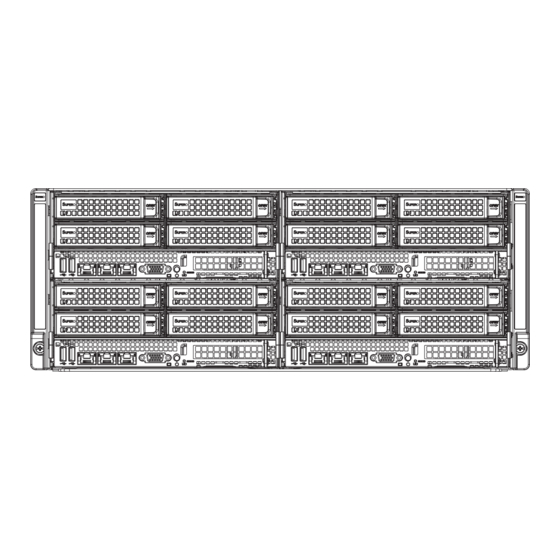
FatTwin F628R3-FC0 USER'S MANUAL Figure 6-1. Front and Rear Chassis Views Hot-Swap SAS/SATA Drives (16) Control Panel Control Panel Ethernet Ports IPMI LAN Port USB Ports VGA Port Power Supply Chassis Fan Control Panel The control panel for each node is located on the front of the chassis. The LEDs inform you of system status. -
Page 85: Removing The Power Cord
Chapter 6: Advanced Chassis Setup Removing the Power Cord Before performing any setup or maintenance on the chassis, use the following procedure to ensure that power has been removed disconnected from the system. Removing the Power Cord 1. Use the operating system to power down the system, following the on-screen prompts. -
Page 86: Installing And Removing Hard Drives
FatTwin F628R3-FC0 USER'S MANUAL Installing and Removing Hard Drives The F424AF chassis contains individual motherboards in separate 2U nodes. Each motherboard node controls the hard drives contained within that node. Note that if a motherboard node is pulled out of the chassis, the hard drives associated with that node will power down as well. -
Page 87: Removing Hard Drives From The Front Of The Node
Chapter 6: Advanced Chassis Setup Removing Hard Drives from the Front of the Node Removing Hard Drive Carriers from the Chassis 1. Press the release button on the drive carrier. This extends the drive bay handle. 2. Use the handle to pull the drive carrier out of the chassis. Figure 6-3: Removing a Hard Drive Carrier from the Front of the Node... -
Page 88: Installing Hard Drives Into The Drive Carriers
FatTwin F628R3-FC0 USER'S MANUAL Installing Hard Drives into the Drive Carriers The hard drives are mounted in drive carriers to simplify their installation and removal from the chassis. These carriers also help promote proper airfl ow through the drive bays. - Page 89 Chapter 6: Advanced Chassis Setup Figure 6-5: Installing a Hard Drive into the Drive Carrier SAS or SATA Hard Drive Drive Carrier Caution: Enterprise level hard disk drives are recommended for use in Supermicro chassis and servers. For information on recommended HDDs, visit the Supermicro Web site at http://www.supermicro.com/products/nfo/fi...
-
Page 90: Node Confi Gurations
FatTwin F628R3-FC0 USER'S MANUAL Node Confi gurations Node confi guration specifi cations are shown in the table below. F424AF-R1K28BP Front of Node Rear of Node One low-profi le expansion PCIE slot, None four (4) 3.5" HDDs Figure 6-6: F424AF Node... -
Page 91: Removing The Node Cover
Chapter 6: Advanced Chassis Setup Removing the Node Cover Each node has a removable cover which will permit access to the nodes compo- nents. Removing the Node Cover 1. Power down the system and remove the power cord from the rear of the power supply as described in Section 6-3. -
Page 92: Removing And Installing The Backplane
FatTwin F628R3-FC0 USER'S MANUAL Removing and Installing the Backplane The F424AF chassis backplane is located behind the hard drives and in front of the motherboard in each motherboard node. Although backplane failure rarely occurs, in the event of a backplane failure, follow the instructions below. -
Page 93: Installing The Backplane
Chapter 6: Advanced Chassis Setup Installing the Backplane Installing the Backplane into the Chassis 1. Ensure that all of the hard drive carriers have been removed from the bays in the front of the node (see 6-4 Installing and Removing Hard Drives). 1. -
Page 94: Installing The Motherboard
FatTwin F628R3-FC0 USER'S MANUAL Installing the Motherboard Compatible Motherboards For the most up-to-date information on compatible motherboards and other parts, visit the Supermicro Web site at www.supermicro.com. Permanent and Optional Standoffs Standoffs prevent short circuits by creating space between the motherboard and the fl... - Page 95 Chapter 6: Advanced Chassis Setup 7. Connect the cables between the motherboard, backplane, chassis, front panel, and power supply, as needed. The fans may be temporarily removed to allow access to the backplane ports. 8. Replace the expansion card bracket and secure the bracket with a screw. 9.
-
Page 96: Installing Front And Rear Expansion Cards
FatTwin F628R3-FC0 USER'S MANUAL Installing Front and Rear Expansion Cards PCIE Slot Setup The nodes of some F424AF chassis models support expansion cards and or Micro LP cards. To install low-profi le expansion cards, follow the instructions on the following pages. -
Page 97: Assembling The Pcie Slot Bracket Assembly
Chapter 6: Advanced Chassis Setup Assembling the PCIE Slot Bracket Assembly Each node supports one expansion card. This expansion card must be plugged into a riser card, which in turn plugs into the motherboard. Assembling the PCIE Slot Bracket Assembly 1. - Page 98 FatTwin F628R3-FC0 USER'S MANUAL 7. Assemble the riser card as illustrated below, securing the riser card to the riser card bracket with the two screws provided. Figure 6-13: Assembling the PCIE Slot Bracket and Riser Card PCIE Slot Bracket Riser Card...
-
Page 99: Checking The Airfl Ow
Chapter 6: Advanced Chassis Setup 6-10 Checking the Airfl ow Checking Airfl ow 1. Make sure there are no objects to obstruct airfl ow in and out of the server. In addition, if you are using a front bezel, make sure the bezel's fi lter is replaced periodically. -
Page 100: 6-11 Replacing System Fans
FatTwin F628R3-FC0 USER'S MANUAL 6-11 Replacing System Fans System fans provide cooling for the system and circulate air through the node as a means of lowering the internal temperature. The F424AF system fans are easily removed from the fan tray. There is no need to uninstall any other parts when replacing fans, and only a Phillips screwdriver is required for installation. -
Page 101: 6-12 Replacing The Power Supply
Chapter 6: Advanced Chassis Setup 6-12 Replacing the Power Supply The F424AF chassis includes a 1280 Watt power supply. This power supply is auto- switching capable. This enables it to automatically sense and operate at a 100v to 240v input voltage. An amber light will be illuminated on the power supply when the power is off. - Page 102 FatTwin F628R3-FC0 USER'S MANUAL Notes 6-20...
-
Page 103: Chapter 7 Bios
Chapter 7: BIOS Chapter 7 BIOS Introduction This chapter describes the AMI BIOS Setup Utility for the X10DRFF-C serverboard. The 16 MB AMI SPI BIOS® Flash ROM is stored in a Flash EEPROM and can be easily updated. This chapter describes the basic navigation of the AMI BIOS Setup Utility setup screens. -
Page 104: Starting The Setup Utility
FatTwin F628R3-FC0 FatTwin Starting the Setup Utility Normally, the only visible Power-On Self-Test (POST) routine is the memory test. As the memory is being tested, press the <Delete> key to enter the main menu of the AMI BIOS Setup utility. From the main menu, you can access the other setup screens. - Page 105 Chapter 7: BIOS System Date/System Time Use this option to change the system date and time. Highlight System Date or System Time using the arrow keys. Enter new values using the keyboard. Press the <Tab> key or the arrow keys to move between fi elds. The date must be entered in Day MM/DD/YYYY format.
-
Page 106: Advanced Setup Confi Gurations
FatTwin F628R3-FC0 FatTwin Advanced Setup Confi gurations Use the arrow keys to select Advanced setup and press <Enter> to access the submenu items: Warning: Take Caution when changing the Advanced settings. An incorrect value, a very high DRAM frequency or an incorrect BIOS timing setting may cause the system to malfunction. - Page 107 Chapter 7: BIOS Bootup Num-Lock State Use this feature to set the Power-on state for the Numlock key. The options are Off and On. Wait For 'F1' If Error Select Enabled to force the system to wait until the 'F1' key is pressed if an error occurs.
- Page 108 FatTwin F628R3-FC0 FatTwin Power Button Function This feature controls how the system shuts down when the power button is pressed. Select 4 Seconds Override for the user to power off the system after pressing and holding the power button for 4 seconds or longer. Select Instant Off to instantly power off the system as soon as the user presses the power button.
- Page 109 Chapter 7: BIOS Cores Enabled This feature allows the user to set the number of CPU cores to enable. Enter "0" to enable all cores. There are 14 cores available in the system. The default setting is 0. Execute-Disable Bit (Available if supported by the OS & the CPU) Select Enable for Execute Disable Bit Technology support, which will allow the processor to designate areas in the system memory where an application code can execute and where it cannot, thus preventing a worm or a virus from fl...
- Page 110 FatTwin F628R3-FC0 FatTwin DCU Mode Use this feature to set the data-prefecting mode for the DCU (Data Cache Unit). The options are 32KB 8Way Without ECC and 16KB 4Way With ECC. Direct Cache Access (DCA) Select Enable to use Intel DCA (Direct Cache Access) Technology to improve the effi...
- Page 111 Chapter 7: BIOS Advanced Power Management Confi guration Advanced Power Management Confi guration Power Technology Select Energy Effi cient to support power-saving mode. Select Custom to customize system power settings. Select Max Performance to optimize system performance. Select Disabled to disable power-saving settings. The options are Disable, Energy Effi...
- Page 112 FatTwin F628R3-FC0 FatTwin CPU C State Control (Available when Power Technology is set to Custom) Package C State limit Use this item to set the limit on the C-State package register. The options are C0/1 state, C2 state, C6 (non-Retention) state, and C6 (Retention) state.
- Page 113 Chapter 7: BIOS Chipset Confi guration Warning! Please set the correct settings for the items below. A wrong confi guration setting may cause the system to become malfunction. North Bridge This feature allows the user to confi gure the settings for the Intel North Bridge. IIO Confi...
- Page 114 FatTwin F628R3-FC0 FatTwin IOAT (Intel® IO Acceleration) Confi guration Enable IOAT Select Enable to enable Intel I/OAT (I/O Acceleration Technology) support, which will signifi cantly reduce CPU overhead by leveraging CPU architectural improvements and freeing the system resource for other tasks. The options are Enable and Disable.
- Page 115 Chapter 7: BIOS QPI (Quick Path Interconnect) Confi guration QPI Status The following information will display: • Number of CPU • Number of IIO • Current QPI Link Speed • Current QPI Link Frequency • QPI Global MMIO Low Base/Limit •...
- Page 116 FatTwin F628R3-FC0 FatTwin Memory Confi guration Enforce POR Select Enable to enforce POR restrictions on DDR4 frequency and voltage programming. The options are Enabled and Disabled. Memory Frequency Use this feature to set the maximum memory frequency for onboard memory modules.
- Page 117 Chapter 7: BIOS Rank Interleaving Use this item to select the memory interleaving mode for memory ranks. The options are Auto, 1-Way, 2-Way, 4-Way, and 8-Way. A7 Mode Select Enabled to support the A7 (Addressing) mode to improve memory performance. The options are Enable and Disable. DIMM Information This item displays the status of a DIMM module as detected by the BIOS.
- Page 118 FatTwin F628R3-FC0 FatTwin Patrol Scrub Interval This feature allows you to decide how many hours the system should wait before the next complete patrol scrub is performed. Use the keyboard to enter a value from 0-24. The Default setting is 24.
- Page 119 Chapter 7: BIOS USB Mass Storage Driver Support Select Enabled for USB mass storage device support. The options are Disabled and Enabled. Port 60/64 Emulation Select Enabled for I/O port 60h/64h emulation support, which in turn, will provide complete legacy USB keyboard support for the operating systems that do not support legacy USB devices.
- Page 120 FatTwin F628R3-FC0 FatTwin SATA Confi guration When this submenu is selected, AMI BIOS automatically detects the presence of the SATA devices that are supported by the Intel PCH chip and displays the following items: SATA Controller This item enables or disables the onboard SATA controller supported by the Intel PCH chip.
- Page 121 Chapter 7: BIOS Port 0 ~ Port 5 SATA Device Type Use this item to specify if the SATA port specifi ed by the user should be connected to a Solid State drive or a Hard Disk Drive. The options are Hard Disk Drive and Solid State Drive.
- Page 122 FatTwin F628R3-FC0 FatTwin Port 0~ Port 5 Select Enabled to enable a SATA port specifi ed by the user. The options are Disabled and Enabled. Port 0 ~ Port 5 Hot Plug Select Enabled to enable hot-plugging support for a port specifi ed by the user, which will allow the user to replace a SATA disk drive installed on this port without shutting down the system.
- Page 123 Chapter 7: BIOS sSATA Port 0~ Port 3 This item displays the information detected on the installed on the sSATA port. specifi ed by the user. • Model number of drive and capacity • Software Preserve Support sSATA Port 0~ Port 3 Select Enabled to enable an sSATA port specifi...
- Page 124 FatTwin F628R3-FC0 FatTwin Support Aggressive Link Power Management When this item is set to Enabled, the SATA AHCI controller manages the power usage of the SATA link. The controller will put the link to a low power state when the I/O is inactive for an extended period of time, and the power state will return to normal when the I/O becomes active.
- Page 125 Chapter 7: BIOS Server ME (Management Engine) Confi guration This feature displays the following system ME confi guration settings. • General ME Confi guration • Operational Firmware Version • Recovery Firmware Version • ME Firmware Features • ME Firmware Status #1 •...
- Page 126 FatTwin F628R3-FC0 FatTwin Maximum Read Request Select Auto for the system BIOS to automatically set the maximum size for a read request for a PCI-E device to enhance system performance. The options are Auto, 128 Bytes, 256 Bytes, 512 Bytes, 1024 Bytes, 2048 Bytes, and 4096 Bytes.
- Page 127 Chapter 7: BIOS Network Stack Select Enabled to enable PXE (Preboot Execution Environment) or UEFI (Unifi ed Extensible Firmware Interface) for network stack support. The options are Enabled and Disabled. Super IO Confi guration Super IO Chip AST2400 COM1 Confi guration/SOL (Serial-Over-LAN) Confi guration COM1/SOL Select Enabled to enable the onboard serial port specifi...
- Page 128 FatTwin F628R3-FC0 FatTwin COM1 Console Redirection Settings Terminal Type This feature allows the user to select the target terminal emulation type for Console Redirection. Select VT100 to use the ASCII Character set. Select VT100+ to add color and function key support. Select ANSI to use the Extended ASCII Character Set.
- Page 129 Chapter 7: BIOS VT-UTF8 Combo Key Support Select Enabled to enable VT-UTF8 Combination Key support for ANSI/VT100 terminals. The options are Enabled and Disabled. Recorder Mode Select Enabled to capture the data displayed on a terminal and send it as text messages to a remote server.
- Page 130 FatTwin F628R3-FC0 FatTwin SOL Console Redirection Settings Use this feature to specify how the host computer will exchange data with the client computer, which is the remote computer used by the user. Terminal Type Use this feature to select the target terminal emulation type for Console Redirection.
- Page 131 Chapter 7: BIOS VT-UTF8 Combo Key Support Select Enabled to enable VT-UTF8 Combination Key support for ANSI/VT100 terminals. The options are Enabled and Disabled. Recorder Mode Select Enabled to capture the data displayed on a terminal and send it as text messages to a remote server.
- Page 132 FatTwin F628R3-FC0 FatTwin EMS Console Redirection Settings (Available when EMS Console Redirection is enabled) Use this feature to specify how the host computer will exchange data with the client computer, which is the remote computer used by the user. Out-of-Band Management Port...
- Page 133 Chapter 7: BIOS Trusted Computing (Available when a TPM device is installed and detected by the BIOS) Confi guration Security Device Support If this feature and the TPM jumper on the serverboard are both set to Enabled, onboard security devices will be enabled for TPM (Trusted Platform Module) support to enhance data integrity and network security.
- Page 134 FatTwin F628R3-FC0 FatTwin ACPI Settings WHEA Support Select Enabled to support the Windows Hardware Error Architecture (WHEA) platform and provide a common infrastructure for the system to handle hardware errors within the Windows OS environment to reduce system crashes and to enhance system recovery and health monitoring.
-
Page 135: Event Logs
Chapter 7: BIOS Event Logs Use this feature to confi gure Event Log settings. Change SMBIOS Event Log Settings This feature allows the user to confi gure SMBIOS Event settings. Enabling/Disabling Options SMBIOS Event Log Select Enabled to enable SMBIOS (System Management BIOS) Event Logging during system boot. - Page 136 FatTwin F628R3-FC0 FatTwin PCI-Ex (PCI-Express) Error Enable Select Yes for the BIOS to correct errors occurred in the PCI-E slots. The options are Yes and No. Memory Correctable Error Threshold Use this item to enter the threshold value for correctable memory errors. The default setting is 10.
-
Page 137: Ipmi
Chapter 7: BIOS IPMI Use this feature to confi gure Intelligent Platform Management Interface (IPMI) settings. IPMI Firmware Revision This item indicates the IPMI fi rmware revision used in your system. IPMI Status This item indicates the status of the IPMI fi rmware installed in your system. ... - Page 138 FatTwin F628R3-FC0 FatTwin Erasing Settings Erase SEL Select Yes, On next reset to erase all system event logs upon next system reboot. Select Yes, On every reset to erase all system event logs upon each system reboot. Select No to keep all system event logs after each system reboot. The options are No, Yes, On next reset, and Yes, On every reset.
-
Page 139: Security Settings
Chapter 7: BIOS Station MAC Address This item displays the Station MAC address for this computer. Mac addresses are 6 two-digit hexadecimal numbers. Gateway IP Address This item displays the Gateway IP address for this computer. This should be in decimal and in dotted quad form (i.e., 192.168.10.253). -
Page 140: Boot Settings
FatTwin F628R3-FC0 FatTwin Administrator Password Use this feature to set the administrator password which is required before the user entering the BIOS setup utility. The length of the password should be from 3 characters to 20 characters long. User Password Use this feature to set the user password which is required to enter the BIOS setup utility. - Page 141 Chapter 7: BIOS Boot Mode Select Use this item to select the type of device to be used for system boot. The options are Legacy, UEFI, and Dual. Fixed Boot Order Priorities This option prioritizes the order of bootable devices from which the system will boot. Press <Enter>...
-
Page 142: Save & Exit
FatTwin F628R3-FC0 FatTwin Delete Boot Option Select the target boot device to delete. Hard Disk Drive BBS Priorities • Legacy Boot Order #1 • Legacy Boot Order #2 Network Drive BBS Priorities • Legacy Boot Order #1 UEFI Application Boot Priorities •... - Page 143 Chapter 7: BIOS Save Changes and Reset When you have completed the system confi guration changes, select this option to leave the BIOS setup utility and reboot the computer for the new system confi guration parameters to take effect. Select Save Changes and Exit from the Exit menu and press <Enter>.
- Page 144 FatTwin F628R3-FC0 FatTwin Notes 7-42...
-
Page 145: Appendix A Bios Error Beep Codes
Appendix A: BIOS Error Beep Codes Appendix A BIOS Error Beep Codes During the POST (Power-On Self-Test) routines, which are performed each time the system is powered on, errors may occur. Non-fatal errors are those which, in most cases, allow the system to continue the boot-up process. - Page 146 FatTwin F628R3-FC0 USER'S MANUAL Notes...
-
Page 147: Appendix B System Specifi Cations
Note: Check the Supermicro website (www.supermicro.com) for the latest memory support information. SAS/SATA Drive Bays Each node of the FatTwin F628R3-FC0 contains four (4) hot-swap drive bays to house four standard 3.5" SAS/SATA drives PCI Expansion The FatTwin F628R3-FC0 has 1x PCI-E 3.0 x16 low-profi le slot available per node. - Page 148 FatTwin F628R3-FC0 USER'S MANUAL Chassis F424AF-R1K28BP (4U rackmount) Dimensions: (WxHxD) 17.63 x 6.96 x 29 in. (448 x 177 x 737 mm) Weight Gross (Bare Bone): 150 lbs. (68.04 kg.) System Cooling The system has eight (8) 8-cm PWM system cooling fans in the chassis rear Note: The fans in this system are redundant and hot-plug.
- Page 149 Appendix B: System Specifi cations Regulatory Compliance Electromagnetic Emissions: FCC Class A, EN 55022 Class A, EN 61000-3-2/-3- 3, CISPR 22 Class A Electromagnetic Immunity: EN 55024/CISPR 24, (EN 61000-4-2, EN 61000-4-3, EN 61000-4-4, EN 61000-4-5, EN 61000-4-6, EN 61000-4-8, EN 61000-4-11) Safety: CSA/EN/IEC/UL 60950-1 Compliant, UL or CSA Listed (USA and Canada), CE Marking (Europe) California Best Management Practices Regulations for Perchlorate Materials:...
- Page 150 FatTwin F628R3-FC0 USER'S MANUAL (continued from front) The products sold by Supermicro are not intended for and will not be used in life support systems, medical equipment, nuclear facilities or systems, aircraft, aircraft devices, aircraft/emergency communication devices or other critical systems whose failure to perform be reasonably expected to result in signifi...
Need help?
Do you have a question about the FatTwin F628R3-FC0 and is the answer not in the manual?
Questions and answers