Table of Contents
Advertisement
Quick Links
Advertisement
Table of Contents

Related Manuals for Supero Supero 6017R-73THDP+


Summary of Contents for Supero Supero 6017R-73THDP+
- Page 1 UPER ® UPER ERVER 6017R-73THDP+ 6017R-73HDP+ USER’S MANUAL...
- Page 2 Manual Revision 1.0 Release Date: May 29, 2013 Unless you request and receive written permission from Super Micro Computer, Inc., you may not copy any part of this document. Information in this document is subject to change without notice. Other products and companies referred to herein are trademarks or registered trademarks of their respective companies or mark holders.
-
Page 3: About This Manual
Preface Preface About This Manual This manual is written for professional system integrators and PC technicians. It provides information for the installation and use of the SuperServer 6017R- 73THDP+/6017R-73HDP+. Installation and maintenance should be performed by experienced technicians only. Manual Organization Chapter 1: Introduction The fi... - Page 4 UPER ERVER 6017R-73THDP+/6017R-73HDP+ User's Manual Chapter 6: Advanced Chassis Setup Refer to Chapter 6 for detailed information on the SC816LTS-655B server chassis. You should follow the procedures given in this chapter when installing, removing or reconfi guring SAS or peripheral drives and when replacing system power supply modules and cooling fans.
- Page 5 Preface Notes...
-
Page 6: Table Of Contents
UPER ERVER 6017R-73THDP+/6017R-73HDP+ User's Manual Table of Contents Chapter 1 Introduction Overview ......................1-1 Serverboard Features ..................1-2 Processors ...................... 1-2 Memory ......................1-2 Onboard SAS ....................1-2 Onboard Serial ATA ..................1-2 Rear I/O Ports ....................1-2 Graphics Controller ..................1-2 Server Chassis Features ................ - Page 7 Table of Contents Chapter 3 System Interface Overview ......................3-1 Control Panel Button ..................3-1 Power ......................3-1 Chapter 4 Standardized Warning Statements for AC Systems About Standardized Warning Statements ............4-1 Warning Defi nition ................... 4-1 Installation Instructions ..................4-4 Circuit Breaker ....................
- Page 8 UPER ERVER 6017R-73THDP+/6017R-73HDP+ User's Manual 5-11 SAS/SATA Port Connections ................. 5-19 5-12 Installing Software ..................5-20 SuperDoctor III ....................5-21 5-13 Onboard Battery .................... 5-22 Chapter 6 Advanced Chassis Setup Static-Sensitive Devices .................. 6-1 Precautions ..................... 6-1 Unpacking ....................... 6-1 Removing the Covers ..................
-
Page 9: Chapter 1 Introduction
Chapter 1: Introduction Chapter 1 Introduction Overview The SuperServer 6017R-73THDP+/6017R-73HDP+ is a high-end server comprised of two main subsystems: the SC816LTS-655B 1U server chassis and the X9DRFF- 7TG+/X9DRFF-7G+ dual processor serverboard. Please refer to our web site for information on operating systems that have been certifi ed for use with the system (www.supermicro.com). -
Page 10: Serverboard Features
UPER ERVER 6017R-73THDP+/6017R-73HDP+ User's Manual Serverboard Features At the heart of the SuperServer 6017R-73THDP+/6017R-73HDP+ lies the X9DRFF- 7TG+/X9DRFF-7G+, a dual processor serverboard based on the Intel® C602 chipset. Below are the main features of the serverboard. (See Figure 1-1 for a block diagram of the chipset.) Processors The X9DRFF-7TG+/X9DRFF-7G+ supports single or dual Intel®... -
Page 11: Server Chassis Features
Chapter 1: Introduction Server Chassis Features The 6017R-73THDP+/6017R-73HDP+ is built upon the SC816LTS-655B chassis. Details on the chassis and on servicing procedures can be found in Chapter 6. The following is a general outline of the main features of the chassis. System Power The SC816LTS-655B features a single 650W power supply consisting of a single power module. -
Page 12: System Block Diagram
UPER ERVER 6017R-73THDP+/6017R-73HDP+ User's Manual Figure 1-1. Intel C602 Chipset: System Block Diagram Note: This is a general block diagram. Please see Chapter 5 for details. Gen3 x16 x16 Gen3 x8 SAS2 #1 SAS2 #2 SAS2 #3 CPU1 SAS2 #4 SAS2308 SAS2 #5 Rear (Fan Side) -
Page 13: Contacting Supermicro
Chapter 1: Introduction Contacting Supermicro Headquarters Address: Super Micro Computer, Inc. 980 Rock Ave. San Jose, CA 95131 U.S.A. Tel: +1 (408) 503-8000 Fax: +1 (408) 503-8008 Email: marketing@supermicro.com (General Information) support@supermicro.com (Technical Support) Web Site: www.supermicro.com Europe Address: Super Micro Computer B.V. - Page 14 UPER ERVER 6017R-73THDP+/6017R-73HDP+ User's Manual Notes...
-
Page 15: Chapter 2 Server Installation
Chapter 2: Server Installation Chapter 2 Server Installation Overview This chapter provides a quick setup checklist to get your SuperServer 6017R- 73THDP+/6017R-73HDP+ up and running. Following the steps in the order given should enable you to have the system operational within a minimal amount of time. This quick setup assumes that your system has come to you with the processor and memory preinstalled. -
Page 16: Warnings And Precautions
UPER ERVER 6017R-73THDP+/6017R-73HDP+ User's Manual installation only in a Restricted Access Location (dedicated equipment rooms, service closets and the like). • This product is not suitable for use with visual display work place devices acccording to §2 of the the German Ordinance for Work with Visual Display Units. -
Page 17: Rack Mounting Considerations
Chapter 2: Server Installation Rack Mounting Considerations Ambient Operating Temperature If installed in a closed or multi-unit rack assembly, the ambient operating tempera- ture of the rack environment may be greater than the ambient temperature of the room. Therefore, consideration should be given to installing the equipment in an environment compatible with the manufacturer’s maximum rated ambient tempera- ture (Tmra). -
Page 18: Rack Mounting Instructions
UPER ERVER 6017R-73THDP+/6017R-73HDP+ User's Manual Rack Mounting Instructions This section provides information on installing the chassis into a rack unit with the rails provided. There are a variety of rack units on the market, which may mean that the assembly procedure will differ slightly from the instructions provided. You should also refer to the installation instructions that came with the rack unit you are using. -
Page 19: Attaching The Inner Rail
Chapter 2: Server Installation Attaching the Inner Rail The SC816LT chassis ships with the inner rails already installed. In most cases it is only necessary to install the inner rail extention. Releasing Inner Rail from the Outer Rails 1. Identify the left and right inner rails and inner rail extensions as illustrated in Figure 6-1. -
Page 20: Installing The Outer Rails To The Rack
UPER ERVER 6017R-73THDP+/6017R-73HDP+ User's Manual Flat head M5 x 12 mm [0.472] Washer for M5 Secure to the Rear of the Rack Attach Outer Rack Rails Together Secure to the Front of the Rack Figure 2-3. Assembling the Outer Rails Installing the Outer Rails to the Rack Installing the Outer Rails 1. - Page 21 Chapter 2: Server Installation Figure 2-4. Attaching the Outer Rails to a Rack 2. Adjust both the short and long brackets to the proper distance so that the rail fi ts snugly into the rack. 3. Secure the long bracket to the front side of the outer rail with two M5 screws and the short bracket to the rear side of the outer rail with three M5 screws.
-
Page 22: Chassis Installation
UPER ERVER 6017R-73THDP+/6017R-73HDP+ User's Manual Figure 2-5. Installing the Chassis into a Rack Note: fi gures are for illustrative purposes only. Always install servers into racks from the bottom up. Chassis Installation Installing the Chassis into a Rack 1. Confi rm that the rails are correctly installed on the rack. 2. -
Page 23: Chapter 3 System Interface
Chapter 3: System Interface Chapter 3 System Interface Overview The server chassis has a single power on/off button. No other buttons or indicators are needed on the Hadoop server. Control Panel Button The power on/off button is located just to the right of the COM port on the front of the chassis. - Page 24 UPER ERVER 6017R-73THDP+/6017R-73HDP+ User's Manual Notes...
-
Page 25: Chapter 4 Standardized Warning Statements For Ac Systems
Chapter 4: Warning Statements for AC Systems Chapter 4 Standardized Warning Statements for AC Systems About Standardized Warning Statements The following statements are industry standard warnings, provided to warn the user of situations which have the potential for bodily injury. Should you have questions or experience difficulty, contact Supermicro's Technical Support department for assistance. - Page 26 UPER ERVER 6017R-73THDP+/6017R-73HDP+ User's Manual Warnung WICHTIGE SICHERHEITSHINWEISE Dieses Warnsymbol bedeutet Gefahr. Sie befi nden sich in einer Situation, die zu Verletzungen führen kann. Machen Sie sich vor der Arbeit mit Geräten mit den Gefahren elektrischer Schaltungen und den üblichen Verfahren zur Vorbeugung vor Unfällen vertraut.
- Page 27 Warning Statements for AC Systems ﺟﺴﺪﻳﺔ ﺍﺻﺎﺑﺔ ﺗﺘﺴﺒﺐ ﻓﻲ ﺣﺎﻟﺔ ﻳﻤﻜﻦ ﺃﻥ ﺍﻧﻚ ﻓﻲ ﺧﻄﺮ ﻳﻌﻨﻲ ﻫﺬﺍ ﺍﻟﺮﻣﺰ !ﺗﺤﺬﻳﺮ ﺍﻟﺪﻭﺍﺋﺮ ﺑﺎﻟﻤﺨﺎﻁﺮ ﺍﻟﻨﺎﺟﻤﺔ ﻋﻦ ﻦ ﻋﻠﻰ ﻋﻠﻢ ، ﻛ ﻣﻌﺪﺍﺕ ﺗﻌﻤﻞ ﻋﻠﻰ ﺃﻱ ﻗﺒﻞ ﺃﻥ ﺍﻟﻜﻬﺮﺑﺎﺋﻴﺔ ﺣﻮﺍﺩﺙ ﺃﻱ ﻭﻗﻮﻉ ﻤﻨﻊ ﻟ ﺍﻟﻮﻗﺎﺋﻴﺔ...
-
Page 28: Installation Instructions
UPER ERVER 6017R-73THDP+/6017R-73HDP+ User's Manual Installation Instructions Warning! Read the installation instructions before connecting the system to the power source. 警告 将此系统连接电源前,请先阅读安装说明。 警告 將系統與電源連接前,請先閱讀安裝說明。 Warnung Vor dem Anschließen des Systems an die Stromquelle die Installationsanweisungen lesen. ¡Advertencia! Lea las instrucciones de instalación antes de conectar el sistema a la red de alimentación. -
Page 29: Circuit Breaker
Chapter 4: Warning Statements for AC Systems Circuit Breaker Warning! This product relies on the building's installation for short-circuit (overcurrent) protection. Ensure that the protective device is rated not greater than: 250 V, 20 A. 警告 此产品的短路(过载电流)保护由建筑物的供电系统提供,确保短路保护设备的额定电 流不大于250V,20A。 警告 此產品的短路(過載電流)保護由建築物的供電系統提供,確保短路保護設備的額定電 流不大於250V,20A。... -
Page 30: Power Disconnection Warning
UPER ERVER 6017R-73THDP+/6017R-73HDP+ User's Manual Waarschuwing Dit product is afhankelijk van de kortsluitbeveiliging (overspanning) van uw electrische installatie. Controleer of het beveiligde aparaat niet groter gedimensioneerd is dan 220V, 20A. Power Disconnection Warning Warning! The system must be disconnected from all sources of power and the power cord removed from the power supply module(s) before accessing the chassis interior to install or remove system components. - Page 31 Chapter 4: Warning Statements for AC Systems ¡Advertencia! El sistema debe ser disconnected de todas las fuentes de energía y del cable eléctrico quitado de los módulos de fuente de alimentación antes de tener acceso el interior del chasis para instalar o para quitar componentes de sistema. Attention Le système doit être débranché...
-
Page 32: Equipment Installation
UPER ERVER 6017R-73THDP+/6017R-73HDP+ User's Manual Equipment Installation Warning! Only trained and qualifi ed personnel should be allowed to install, replace, or service this equipment. 警告 只有经过培训且具有资格的人员才能进行此设备的安装、更换和维修。 警告 只有經過受訓且具資格人員才可安裝、更換與維修此設備。 Warnung Das Installieren, Ersetzen oder Bedienen dieser Ausrüstung sollte nur geschultem, qualifi ziertem Personal gestattet werden. ¡Advertencia! Solamente el personal califi... -
Page 33: Restricted Area
Chapter 4: Warning Statements for AC Systems Waarschuwing Deze apparatuur mag alleen worden geïnstalleerd, vervangen of hersteld door geschoold en gekwalifi ceerd personeel. Restricted Area Warning! This unit is intended for installation in restricted access areas. A restricted access area can be accessed only through the use of a special tool, lock and key, or other means of security. -
Page 34: Battery Handling
UPER ERVER 6017R-73THDP+/6017R-73HDP+ User's Manual אזור עם גישה מוגבלת !אזהרה יש להתקין את היחידה באזורים שיש בהם הגבלת גישה. הגישה ניתנת בעזרת .('כלי אבטחה בלבד )מפתח, מנעול וכד ﻣﺤﻈﻮﺭﺓ ﻣﻨﺎﻁﻖ ﻟﺘﺮﻛﻴﺒﻬﺎ ﻓﻲ ﻫﺬﻩ ﺍﻟﻮﺣﺪﺓ ﺗﺨﺼﻴﺺ ﺗﻢ ،ﺃﺩﺍﺓ ﺧﺎﺻﺔ ﻣﻦ ﺧﻼﻝ ﺍﺳﺘﺨﺪﺍﻡ ﻓﻘﻂ... - Page 35 Chapter 4: Warning Statements for AC Systems Warnung Bei Einsetzen einer falschen Batterie besteht Explosionsgefahr. Ersetzen Sie die Batterie nur durch den gleichen oder vom Hersteller empfohlenen Batterietyp. Entsorgen Sie die benutzten Batterien nach den Anweisungen des Herstellers. Attention Danger d'explosion si la pile n'est pas remplacée correctement. Ne la remplacer que par une pile de type semblable ou équivalent, recommandée par le fabricant.
-
Page 36: Redundant Power Supplies
UPER ERVER 6017R-73THDP+/6017R-73HDP+ User's Manual Redundant Power Supplies Warning! This unit might have more than one power supply connection. All connections must be removed to de-energize the unit. 警告 此部件连接的电源可能不止一个,必须将所有电源断开才能停止给该部件供电。 警告 此裝置連接的電源可能不只一個,必須切斷所有電源才能停止對該裝置的供電。 Warnung Dieses Gerät kann mehr als eine Stromzufuhr haben. Um sicherzustellen, dass der Einheit kein trom zugeführt wird, müssen alle Verbindungen entfernt werden. -
Page 37: Backplane Voltage
Chapter 4: Warning Statements for AC Systems ﺍﻣﺪﺍﺩ ﺍﻟﻄﺎﻗﺔ ﺑﻮﺣﺪﺍﺕ ﻋﺪﺓ ﺍﺗﺼﺎﻻﺕ ﺠﻬﺎﺯ ﺍﻟ ﻳﻜﻮﻥ ﻟﻬﺬﺍ ﻗﺪ ﺍﻟﻜﻬﺮﺑﺎء ﻋﻦ ﻮﺣﺪﺓ ﺍﻟ ﻟﻌﺰﻝ ﻛﺎﻓﺔ ﺍﻻﺗﺼﺎﻻﺕ ﻳﺠﺐ ﺇﺯﺍﻟﺔ Waarschuwing Deze eenheid kan meer dan één stroomtoevoeraansluiting bevatten. Alle aansluitingen dienen verwijderd te worden om het apparaat stroomloos te maken. Backplane Voltage Warning! Hazardous voltage or energy is present on the backplane when the system is... -
Page 38: Comply With Local And National Electrical Codes
UPER ERVER 6017R-73THDP+/6017R-73HDP+ User's Manual מתח בפנל האחורי !הרה אז קיימת סכנת מתח בפנל האחורי בזמן תפעול המערכת. יש להיזהר במהלך .העבודה ﺍﻟﻠﻮﺣﺔ ﺃﻭﺍﻟﻄﺎﻗﺔ ﺍﻟﻤﻮﺟﻮﺩﺓ ﻋﻠﻰ ﺍﻟﺘﻴﺎﺭ ﺍﻟﻜﻬﺮﺑﺎﺋﻲ ﻣﻦ ﺧﻄﺮ ﻫﻨﺎﻙ ﻫﺬﺍ ﺍﻟﺠﻬﺎﺯ ﺧﺪﻣﺔ ﻛﻦ ﺣﺬﺭﺍ ﻋﻨﺪ ﻳﻌﻤﻞ ﺍﻟﻨﻈﺎﻡ ﻋﻨﺪﻣﺎ ﻳﻜﻮﻥ Waarschuwing Een gevaarlijke spanning of energie is aanwezig op de backplane wanneer het systeem in gebruik is. -
Page 39: Product Disposal
Chapter 4: Warning Statements for AC Systems Attention L'équipement doit être installé conformément aux normes électriques nationales et locales. תיאום חוקי החשמל הארצי !אזהרה הציוד חייבת להיות תואמת לחוקי החשמל המקומיים והארציים התקנת ﺍﻟﻤﺘﻌﻠﻘﺔ ﺍﻟﻤﺤﻠﻴﺔ ﻭﺍﻟﻮﻁﻨﻴﺔ ﻘﻮﺍﻧﻴﻦ ﻳﺠﺐ ﺃﻥ ﻳﻤﺘﺜﻞ ﻟﻠ ﺍﻟﻜﻬﺮﺑﺎﺋﻴﺔ... -
Page 40: Hot Swap Fan Warning
UPER ERVER 6017R-73THDP+/6017R-73HDP+ User's Manual ¡Advertencia! Al deshacerse por completo de este producto debe seguir todas las leyes y reglamentos nacionales. Attention La mise au rebut ou le recyclage de ce produit sont généralement soumis à des lois et/ou directives de respect de l'environnement. Renseignez-vous auprès de l'organisme compétent. - Page 41 Chapter 4: Warning Statements for AC Systems 警告 當您從機架移除風扇裝置,風扇可能仍在轉動。小心不要將手指、螺絲起子和其他 物品太靠近風扇。 Warnung Die Lüfter drehen sich u. U. noch, wenn die Lüfterbaugruppe aus dem Chassis genommen wird. Halten Sie Finger, Schraubendreher und andere Gegenstände von den Öffnungen des Lüftergehäuses entfernt. ¡Advertencia! Los ventiladores podran dar vuelta cuando usted quite ell montaje del ventilador del chasis.
-
Page 42: Power Cable And Ac Adapter
UPER ERVER 6017R-73THDP+/6017R-73HDP+ User's Manual Power Cable and AC Adapter Warning! When installing the product, use the provided or designated connection cables, power cables and AC adaptors. Using any other cables and adaptors could cause a malfunction or a fi re. Electrical Appliance and Material Safety Law prohibits the use of UL or CSA -certifi... - Page 43 Chapter 4: Warning Statements for AC Systems Attention Lors de l'installation du produit, utilisez les bables de connection fournis ou désigné. L'utilisation d'autres cables et adaptateurs peut provoquer un dysfonctionnement ou un incendie. Appareils électroménagers et de loi sur la sécurité Matériel interdit l'utilisation de UL ou CSA câbles certifi...
- Page 44 UPER ERVER 6017R-73THDP+/6017R-73HDP+ User's Manual Notes 4-20...
-
Page 45: Chapter 5 Advanced Serverboard Setup
Chapter 5: Advanced Serverboard Setup Chapter 5 Advanced Serverboard Setup This chapter covers the steps required to install processors and heatsinks to the X9DRFF-7TG+/X9DRFF-7G+ serverboard, connect the data and power cables and install add-on cards. All serverboard jumpers and connections are described and a layout and quick reference chart are included in this chapter. -
Page 46: Installing The Processor And Heatsink
UPER ERVER 6017R-73THDP+/6017R-73HDP+ User's Manual Installing the Processor and Heatsink Warning: When handling the processor package, avoid placing direct pressure on the label area of the fan. Notes: • Always connect the power cord last and always remove it before adding, re- moving or changing any hardware components. - Page 47 Chapter 5: Advanced Serverboard Setup 3. With the lever labeled 'Close 1st' fully retracted, gently push down on the 'Open 1st' lever to open the load plate. Lift the load plate to open it completely. Gently push 4. Using your thumb and the index down to pop the load plate fi...
- Page 48 UPER ERVER 6017R-73THDP+/6017R-73HDP+ User's Manual Warning: You can only install the CPU to the socket in one direction. Make sure that the CPU is properly inserted into the socket before closing the load plate. If it doesn't close properly, do not force it as it may damage your CPU. Instead, open the load plate again and double-check that the CPU is aligned properly.
-
Page 49: Installing A Cpu Heatsink
Chapter 5: Advanced Serverboard Setup Installing a CPU Heatsink 1. Place the heatsink on top of the CPU so that the four mounting holes are aligned with those on the retention mechanism. 2. Screw in two diagonal screws (i.e. the #1 and the #2 screws) until just snug (do not over-tighten the screws, which may damage the CPU.) 3. -
Page 50: Connecting Cables
UPER ERVER 6017R-73THDP+/6017R-73HDP+ User's Manual Connecting Cables With the processors are installed, the next step is to connect the cables to the serverboard. Connecting Data Cables The cables used to transfer data from the peripheral devices have been carefully routed to prevent them from blocking the fl ow of cooling air that moves through the system from front to back. -
Page 51: Installing Memory
Chapter 5: Advanced Serverboard Setup Installing Memory Note: Check the Supermicro web site for recommended memory modules. CAUTION Exercise extreme care when installing or removing DIMM modules to prevent any possible damage. Installing DIMMs 1. Insert the desired number of DIMMs into the memory slots, starting with slot P1-DIMMA1. - Page 52 UPER ERVER 6017R-73THDP+/6017R-73HDP+ User's Manual Processor & Memory Module Population Confi guration For memory to work properly, follow the tables below for memory installation. Processors and their Corresponding Memory Modules CPU# Corresponding DIMM Modules CPU 1 DIMMA1 DIMMB1 DIMMC1 DIMMD1 DIMMA2 DIMMB2 DIMMC2...
- Page 53 Chapter 5: Advanced Serverboard Setup Installing UDIMM (ECC/Non-ECC) Memory Intel E5-2600 Series Processor UDIMM Memory Support Ranks Per Memory Capacity Speed (MT/s) and Voltage Validated by Slot per DIMM & Per DIMM Channel (SPC) and DIMM Per Channel (DPC) Data Width 1 Slot Per 2 Slots Per Channel (See the Note below)
-
Page 54: Adding Pci Cards
UPER ERVER 6017R-73THDP+/6017R-73HDP+ User's Manual Adding PCI Cards PCI Expansion Slots A riser card (RSC-R1UFF-E8R) installed to the system allow you to add a PCI expansion card. The 6017R-73THDP+/6017R-73HDP+ can support the use of one half-height, full-length) expansion card with the pre-installed riser card. PCI Card Installation Before installing a PCI add-on card, make sure you power off the system fi... -
Page 55: Serverboard Details
Chapter 5: Advanced Serverboard Setup Serverboard Details Figure 5-3. SUPER X9DRFF-7TG+/X9DRFF-7G+ Layout UID_SW1 USB0 VGA1 USB1 IPMI_ LAN LAN1 Intel LAN LAN2 JPME1 CTRL JPME2 JWD1 JI2C2 IPMI CODE JI2C1 USB2 MEGERAC LICENSE Intel PCH SAS CODE BIOS LEDS2 JBT1 X9DRFF-iG+ LSI SAS Rev. -
Page 56: X9Drff-7Tg+/X9Drff-7G+ Quick Reference
UPER ERVER 6017R-73THDP+/6017R-73HDP+ User's Manual X9DRFF-7TG+/X9DRFF-7G+ Quick Reference Jumper Description Default Setting JBT1 Clear CMOS See Section 5-9 C1/JI SMB to PCI-E Slots Open (Disabled) JPB1 BMC Enable Pins 1-2 (Enabled) JPG1 VGA Enable Pins 1-2 (Enabled) JPL1 LAN1/LAN2 Enable Pins 1-2 (Enabled) JPS1 SAS Enable... -
Page 57: Connector Defi Nitions
Chapter 5: Advanced Serverboard Setup Connector Defi nitions ATX Power Connector 12V 8-pin PWR Two 8-pin power connectors (JPW1/ Pin Defi nitions JPW2) and a 4-pin power connector Pins Defi nition 12V 4-pin PWR (JPW3) are used to provide power to 1- 4 Ground Pin Defi... - Page 58 UPER ERVER 6017R-73THDP+/6017R-73HDP+ User's Manual Power Button/Unit Identifi er Switch UID Switch A Unit Identifier switch (SW1) and a Pin# Defi nition UID LED Indicator are located on the Ground serverboard. In addition, a power button Ground (PWR_SW1) is located next to the UID Button In switch on the front panel.
- Page 59 Chapter 5: Advanced Serverboard Setup T-SGPIO 1/2 & 6-SGPIO 1/2 Headers Four SGPIO (Serial-Link General Pur- T-SGPIO/6-SGPIO Pin Defi nitions pose Input/Output) headers (T-SGPIO Pin# Defi nition Defi nition 1/2 & 6-SGPIO 1/2) are located on the serverboard. These headers support on- Ground Data board Serial_Link interface connections.
-
Page 60: Jumper Settings
UPER ERVER 6017R-73THDP+/6017R-73HDP+ User's Manual Jumper Settings Explanation of Jumpers To modify the operation of the serverboard, jumpers can be used Connector to choose between optional settings. Pins Jumpers create shorts between two pins to change the function of the Jumper connector. - Page 61 Chapter 5: Advanced Serverboard Setup Watch Dog Enable/Disable JWD1 controls the Watch Dog function. Watch Dog is a system monitor that can Watch Dog reboot the system when a software appli- Jumper Settings cation “hangs”. Pins 1-2 will cause WD to Jumper Setting Defi...
-
Page 62: 5-10 Onboard Indicators
UPER ERVER 6017R-73THDP+/6017R-73HDP+ User's Manual 5-10 Onboard Indicators LAN LEDs Activity LED Link Speed LED The Ethernet ports (located beside the VGA port) have two LEDs. On each GLAN Activity Indicator (Right) Gigabit LAN port, one LED indicates ac- LED Settings tivity when blinking while the other LED Color Status... -
Page 63: 5-11 Sas/Sata Port Connections
Chapter 5: Advanced Serverboard Setup Failure LED A Failure LED is located at Failure_ Failure LED Status LED1 on the serverboard. When Fail- State Defi nition ure_LED1 is on, power failure has oc- PWR Failure curred. When it is blinking, it indicates Blinking Fan Failure a fan failure. -
Page 64: 5-12 Installing Software
UPER ERVER 6017R-73THDP+/6017R-73HDP+ User's Manual 5-12 Installing Software The Supermicro ftp site contains drivers and utilities for your system at ftp://ftp. supermicro.com. Some of these must be installed, such as the chipset driver. After accessing the ftp site, go into the CDR_Images directory and locate the ISO fi... -
Page 65: Superdoctor Iii
Chapter 5: Advanced Serverboard Setup SuperDoctor III The SuperDoctor® III program is a web-based management tool that supports remote management capability. It includes Remote and Local Management tools. The local management is called SD III Client. The SuperDoctor III program allows you to monitor the environment and operations of your system. -
Page 66: 5-13 Onboard Battery
UPER ERVER 6017R-73THDP+/6017R-73HDP+ User's Manual Figure 5-6. SuperDoctor III Interface Display Screen (Remote Control) Note: The SuperDoctor III program and User’s Manual can be downloaded from the Supermicro web site at http://www.supermicro.com/products/accessories/soft- ware/SuperDoctorIII.cfm. For Linux, we recommend that you use the SuperDoctor II application instead. -
Page 67: Chapter 6 Advanced Chassis Setup
Chapter 6: Advanced Chassis Setup Chapter 6 Advanced Chassis Setup This chapter covers the steps required to install components and perform mainte- nance on the SC816LTS-655B chassis. For component installation, follow the steps in the order given to eliminate the most common problems encountered. If some steps are unnecessary, skip ahead to the step that follows. -
Page 68: Removing The Covers
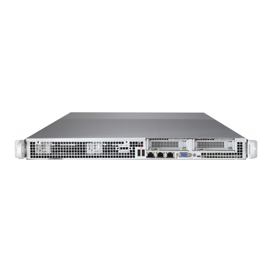
UPER ERVER 6017R-73THDP+/6017R-73HDP+ User's Manual Figure 6-1. Chassis Front View LAN Ports Low-Profi le PCI-E Slot Covers COM Port Power Button UID Button Removing the Covers The SC816LT chassis features both a front and a rear cover, which allow access to the interior of the chassis. -
Page 69: System Fans
Chapter 6: Advanced Chassis Setup System Fans Eight internal system fans in two separate fan housings provide cooling for the system. The system fans are easily removed from the chassis with a screwdriver. Replacing a System Fan 1. Determine the location of the failed fan. If necessary, briefl y remove the chas- sis cover while the system is running in order to locate the failed fan. - Page 70 UPER ERVER 6017R-73THDP+/6017R-73HDP+ User's Manual Left Side Fan Housing Right Side Fan Housing Figure 6-3. Replacing the Left and Right Fan Housings Left Side Fan Housing Right Side Fan Housing Figure 6-4. Left and Right Fan Housings...
-
Page 71: Drive Bay Installation/Removal
Chapter 6: Advanced Chassis Setup Drive Bay Installation/Removal The SC816LT chassis contains twelve fi xed hard drives. Each hard drive and its position in the chassis are labeled with a number that corresponds to the SATA port on the serverboard. Figure 6-5. - Page 72 UPER ERVER 6017R-73THDP+/6017R-73HDP+ User's Manual 5. Lift the HDD up and out of the chassis, noting that the number on the fl oor of the chassis and the corresponding number on the hard drive. 6. Transfer the number on the failed hard drive to the replacement hard drive. 7.
-
Page 73: Installing Expansion Cards
Chapter 6: Advanced Chassis Setup Installing Expansion Cards The SC816LT chassis supports two low-profi le expansion cards Each expansion card connects to the serverboard with a riser card. To install expansion cards, fol- low the instructions below. Installing a Low-Profi le Expansion Card 1. -
Page 74: Replacing The Power Supply
UPER ERVER 6017R-73THDP+/6017R-73HDP+ User's Manual Replacing the Power Supply The 6017R-73THDP+/6017R-73HDP+ includes a 655W power supply. This power supply is auto-switching capable, which enables it to automatically sense and oper- ate at a 100 to 240 input voltage. An amber light will be illuminated on the power supply when the power is off. -
Page 75: Chapter 7 Bios
Chapter 7: BIOS Chapter 7 BIOS Introduction This chapter describes the AMI BIOS Setup utility for the X9DRFF-7G+. It also provides the instructions on how to navigate the AMI BIOS Setup utility screens. The AMI ROM BIOS is stored in a Flash EEPROM and can be easily updated. Starting BIOS Setup Utility To enter the AMI BIOS Setup utility screens, press the <Del>... -
Page 76: How To Change The Confi Guration Data
UPER ERVER 6017R-73THDP+/6017R-73HDP+ User's Manual How To Change the Confi guration Data The confi guration data that determines the system parameters may be changed by entering the AMI BIOS Setup utility. This Setup utility can be accessed by pressing <Delete> at the appropriate time during system boot. Note: For AMI UEFI BIOS Recovery, please refer to the UEFI BIOS Re- covery User Guide posted @http://www.supermicro.com/support/manuals/. - Page 77 Chapter 7: BIOS The AMI BIOS main menu displays the following information: System Date This item displays the system date in Day MM/DD/YY format (e.g. Sat 10/20/2012). System Time This item displays the system time in HH:MM:SS format (e.g. 15:32:52). Supermicro X9DRFF-iG+/iTG+/7G+/7TG+ Version This item displays the SMC version of the BIOS ROM used in this system.
-
Page 78: Advanced Setup Confi Gurations
UPER ERVER 6017R-73THDP+/6017R-73HDP+ User's Manual Advanced Setup Confi gurations Use the arrow keys to select the Advanced Setup submenu and press <Enter> to access the following items. Boot Feature Quiet Boot Use this item to select bootup screen display between POST messages and the OEM logo. - Page 79 Chapter 7: BIOS Interrupt 19 Capture Interrupt 19 is the software interrupt that handles the boot disk function. When this item is set to Enabled, the ROM BIOS of the host adaptors will "capture" Interrupt 19 at bootup and allow the drives that are attached to these host adaptors to function as bootable disks.
- Page 80 UPER ERVER 6017R-73THDP+/6017R-73HDP+ User's Manual Socket 1 CPU Information, Socket 2 CPU Information This submenu displays the following information on the CPUs installed in Socket 1 and Socket 2. • Type of CPU • CPU Signature • Microcode Patch •...
- Page 81 Chapter 7: BIOS RTID (Record Types IDs) This feature displays the total number of Record Type IDs for local and remote pools. The options are Optimal and Alternate. Hyper-threading Select Enabled to support Intel Hyper-threading Technology to enhance CPU per- formance.
- Page 82 UPER ERVER 6017R-73THDP+/6017R-73HDP+ User's Manual DCU IP Prefetcher Select Enabled for DCU (Data Cache Unit) IP Prefetcher support, which will prefetch IP addresses to improve network connectivity and system performance. The options are Enabled and Disabled. ® Intel Virtualization Technology (Available when supported by the CPU) Select Enabled for Intel Virtualization Technology support, which will allow one platform to run multiple operating systems and applications in independent parti- tions, creating multiple "virtual"...
- Page 83 Chapter 7: BIOS CPU C6 Report (Available when Power Technology is set to Custom) Select Enabled to allow the BIOS to report the CPU C6 State (ACPI C3) to the operating system. During the CPU C6 State, the power to all cache is turned off.
-
Page 84: North Bridge
UPER ERVER 6017R-73THDP+/6017R-73HDP+ User's Manual Short Duration Power Limit This item displays the time period during which short duration power (in watts)is maintained. The default setting is 0. Chipset Confi guration North Bridge This feature allows the user to confi gure the settings for the Intel North Bridge. Integrated IO Confi... - Page 85 Chapter 7: BIOS IIO 1 PCIe Port Bifurcation Control This submenu confi gures the following IO PCIe Port Bifurcation Control settings for the PCIe ports. It also determines how the available PCI-Express lanes are distributed between the PCI-Exp. Root ports. CPU 1 Slot J1 PCI-E 3.0 x16 Link Speed Select GEN1 to enable PCI-Exp Generation 1 support for Slot J1.
- Page 86 UPER ERVER 6017R-73THDP+/6017R-73HDP+ User's Manual Current QPI Link Frequency This item displays the frequency of the QPI Link. Isoc Select Enabled to enable Isochronous support to meet QoS (Quality of Service) requirements. This feature is especially important for virtualization technology. The options are Enabled and Disabled.
- Page 87 Chapter 7: BIOS data in memory for data backup. When Lockstep is selected, the motherboard uses two areas of memory to run the same set of operations in parallel. The options are Independent, Mirroring, and Lockstep. DRAM RAPL Mode RAPL (Running Average Power Limit) provides mechanisms to enforce power consumption limits on supported processors The options are DRAM RAPL MODE0, DRAM RAPL MODE1, and Disabled.
- Page 88 UPER ERVER 6017R-73THDP+/6017R-73HDP+ User's Manual Device Tagging Select Enabled to support device tagging. The options are Disabled and En- abled. Thermal Throttling Throttling improves CPU reliability and reduces power consumption via automatic voltage control during processor idle states. The options are Disabled and CLTT (Closed Loop Thermal Throttling).
- Page 89 Chapter 7: BIOS EHCI Hand-Off This item is for operating systems that do not support Enhanced Host Controller Interface (EHCI) hand-off. When this feature is enabled, EHCI ownership will be changed by the EHCI driver. The options are Disabled and Enabled. SATA Confi...
- Page 90 UPER ERVER 6017R-73THDP+/6017R-73HDP+ User's Manual Port 0~5 Staggered Spin-Up Select Enabled to enable Staggered Spin-up support to prevent excessive power consumption caused by multiple HDDs spinning-up simultaneously. The options are Enabled and Disabled. RAID Mode The following items are displayed when RAID Mode is selected: SATA RAID Option ROM/UEFI Driver Use this feature to enable the onboard SATA Option ROM or EFI driver.
- Page 91 Chapter 7: BIOS Maximum Read Request Select Auto to allow the system BIOS to automatically set the maximum Read Request size for a PCI-E device to enhance system performance. The options are Auto, 128 Bytes, 256 Bytes, 512 Bytes, 1024 Bytes, 2048 Bytes, and 4096 Bytes. ASPM Support Use this feature to set the Active State Power Management (ASPM) level for a PCI-E device.
-
Page 92: Serial Port Console Redirection
UPER ERVER 6017R-73THDP+/6017R-73HDP+ User's Manual Load Onboard SAS OPROM Select Enabled for onboard SAS Option ROM support. This is to boot the computer using a SAS device. The options are Disabled and Enabled. VGA Priority This feature allows the user to select the graphics adapter to be used as the primary boot device. - Page 93 Chapter 7: BIOS acter Set. Select VT-UTF8 to use UTF8 encoding to map Unicode characters into one or more bytes. The options are ANSI, VT100, VT100+, and VT-UTF8. Bits Per second Use this feature to set the transmission speed for a serial port used in Console Redirection.
- Page 94 UPER ERVER 6017R-73THDP+/6017R-73HDP+ User's Manual Resolution 100x31 Select Enabled for extended-terminal resolution support. The options are Dis- abled and Enabled. Legacy OS Redirection Resolution Use this feature to select the number of rows and columns used in Console Redirection for legacy OS support. The options are 80x24 and 80x25. Putty KeyPad This feature selects Function Keys and KeyPad settings for Putty, which is a terminal emulator designed for the Windows OS.
-
Page 95: Acpi Settings
Chapter 7: BIOS and function key support. Select ANSI to use the extended ASCII character set. Select VT-UTF8 to use UTF8 encoding to map Unicode characters into one or more bytes. The options are ANSI, VT100, VT100+, and VT-UTF8. Bits Per Second This item sets the transmission speed for a serial port used in Console Redirec- tion. - Page 96 UPER ERVER 6017R-73THDP+/6017R-73HDP+ User's Manual tion embedded in the CPU. The High Performance Event Timer is used to replace the 8254 Programmable Interval Timer. The options are Enabled and Disabled. Trusted Computing (Available when a TPM device is detected by the BIOS) Confi...
-
Page 97: Event Logs
Chapter 7: BIOS Event Logs This submenu allows the user to confi gure Event Log settings. Change SMBIOS Event Log Settings This feature allows the user to confi gure SMBIOS Event settings. Enabling/Disabling Options SMBIOS Event Log Select Enabled to enable SMBIOS (System Management BIOS) event logging dur- ing system boot. -
Page 98: View Smbios Event Log
UPER ERVER 6017R-73THDP+/6017R-73HDP+ User's Manual Erase Event Log Select Enabled to erase the SMBIOS (System Management BIOS) Event Log, which is completed before an event logging is initialized upon system reboot. The options are No, Yes, next reset, and Yes, every reset. When Log is Full Select Erase Immediately to immediately erase SMBIOS error event logs that ex- ceed the limit when the SMBIOS event log is full. -
Page 99: Ipmi
Chapter 7: BIOS IPMI Use this feature to confi gure Intelligent Platform Management Interface (IPMI) settings. IPMI Firmware Revision This item indicates the IPMI fi rmware revision used in your system. IPMI Status This item indicates the status of the IPMI fi rmware installed in your system. ... - Page 100 UPER ERVER 6017R-73THDP+/6017R-73HDP+ User's Manual When SEL is Full This feature allows the user to decide what the BIOS should do when the system event log is full. Select Erase Immediately to erase all events in the log when the system event log is full.
-
Page 101: Boot
Chapter 7: BIOS Boot This submenu allows the user to confi gure the following boot settings for the system. Set Boot Priority 1st Boot Device, 2nd Boot Device, 3rd Boot Device, etc. Use these items to specify the sequence of boot device priority. ... -
Page 102: Security
UPER ERVER 6017R-73THDP+/6017R-73HDP+ User's Manual Security This menu is used to confi gure the following security settings for the system. Password Check This feature determines when a password entry is required. If Setup is selected, the user is required to enter a password upon entering the BIOS setup utility. If Always is selected, the user is required to enter a password upon entering the BIOS setup utility and upon each system boot. -
Page 103: Save & Exit
Chapter 7: BIOS Save & Exit This submenu allows the user to confi gure the Save and Exit settings for the system. Discard Changes and Exit Select this option to quit the BIOS Setup without making any permanent changes to the system confi guration, and reboot the computer. Select Discard Changes and Exit, and press <Enter>. - Page 104 UPER ERVER 6017R-73THDP+/6017R-73HDP+ User's Manual Discard Changes Select this feature and press <Enter> to discard all the changes and return to the BIOS setup. When the dialog box appears, asking you if you want to load previ- ous values, select Yes to load the values previous saved, or select No to keep the changes you've made so far.
-
Page 105: Appendix A Bios Error Beep Codes
Appendix A: BIOS POST Error Codes Appendix A BIOS Error Beep Codes BIOS Error Beep Codes are not available for this motherboard. - Page 106 UPER ERVER 6017R-73THDP+/6017R-73HDP+ User's Manual Notes...
-
Page 107: Appendix B System Specifi Cations
Appendix B: System Specifi cations Appendix B System Specifi cations Processors ® One or two Intel E5-2600 Series processors in LGA2011 sockets Note: refer to our web site for details on supported processors and operating systems. Chipset Intel PCH C602 BIOS 16MB SPI AMI BIOS ®... - Page 108 SUPERSERVER 6017R-73THDP+/6017R-73HDP+ User's Manual Serverboard 6017R-73THDP+: X9DRFF-7TG+ 6017R-73HDP+: X9DRFF-7G+ Dimensions: 8.54 x 18.72 in (217 x 475 mm) Chassis SC816LTS-655BP (1U Rackmount) Dimensions: (WxHxD) 17.2 x 1.7 x 36 in. (437 x 43 x 914 mm) Weight Gross Weight: 38 lbs. (17.3 kg.) System Cooling Eight 4-cm high performance fans System Input Requirements...
- Page 109 Appendix B: System Specifi cations Regulatory Compliance Electromagnetic Emissions: FCC Class A, EN 55022 Class A, EN 61000-3-2/-3- 3, CISPR 22 Class A Electromagnetic Immunity: EN 55024/CISPR 24, (EN 61000-4-2, EN 61000-4-3, EN 61000-4-4, EN 61000-4-5, EN 61000-4-6, EN 61000-4-8, EN 61000-4-11) Safety: CSA/EN/IEC/UL 60950-1 Compliant, UL or CSA Listed (USA and Canada), CE Marking (Europe) California Best Management Practices Regulations for Perchlorate Materials:...
- Page 110 SUPERSERVER 6017R-73THDP+/6017R-73HDP+ User's Manual (continued from front) The products sold by Supermicro are not intended for and will not be used in life support systems, medical equipment, nuclear facilities or systems, aircraft, aircraft devices, aircraft/emergency com- munication devices or other critical systems whose failure to perform be reasonably expected to result in signifi...
Need help?
Do you have a question about the Supero 6017R-73THDP+ and is the answer not in the manual?
Questions and answers