Table of Contents
Advertisement
Quick Links
Advertisement
Table of Contents

Related Manuals for Supero FatTwin F617H6-FT+


Summary of Contents for Supero FatTwin F617H6-FT+
- Page 1 UPER ® FatTwin F617H6-FT+ F617H6-FTPT+ USER'S MANUAL Revision 1.0c...
- Page 2 The information in this User’s Manual has been carefully reviewed and is believed to be accurate. The vendor assumes no responsibility for any inaccuracies that may be contained in this document, makes no commitment to update or to keep current the information in this manual, or to notify any person or organization of the updates.
- Page 3 Preface Preface About This Manual This manual is written for professional system integrators and PC technicians. It provides information for the installation and use of the FatTwin™ F617H6-FT+/FTPT+. Installation and maintainance should be performed by experienced technicians only. The FatTwin F617H6-FT+/FTPT+ is a high-end server based on the F414IS-R1K62B 4U rackmount chassis and a dual processor X9DRFF-7+/7T+ serverboard.
- Page 4 FatTwin F617H6-FT+/FTPT+ USER'S MANUAL Chapter 6: Advanced Chassis Setup Refer to Chapter 6 for detailed information on the F414IS-R1K62B server chassis. You should follow the procedures given in this chapter when installing, removing or reconfi guring SATA or peripheral drives and when replacing system power supply units and cooling fans.
- Page 5 FatTwin F617H6-FT+/FTPT+ USER'S MANUAL Notes...
-
Page 6: Table Of Contents
FatTwin F617H6-FT+/FTPT+ USER'S MANUAL Table of Contents Chapter 1 Introduction Overview ......................1-1 Serverboard Features ..................1-2 Processors ...................... 1-2 Memory ......................1-2 Serial ATA ....................... 1-3 SAS ......................... 1-3 PCI Expansion Slots ..................1-3 Onboard Controllers/Ports ................1-3 Graphics Controller ..................1-3 Nuvoton WPCM450 Controller ............... - Page 7 Table of Contents Choosing a Setup Location ................2-2 Rack Precautions .................... 2-2 Server Precautions ..................2-2 Rack Mounting Considerations ............... 2-3 Ambient Operating Temperature ..............2-3 Reduced Airfl ow ..................2-3 Mechanical Loading ................... 2-3 Circuit Overloading ..................2-3 Reliable Ground ..................
- Page 8 FatTwin F617H6-FT+/FTPT+ USER'S MANUAL Chapter 5 Advanced Motherboard Setup Handling the Motherboard ................5-1 Precautions ..................... 5-1 Unpacking ....................... 5-1 Connecting Cables ..................5-2 Connecting SATA Power Cables ..............5-2 Connecting Data Cables ................. 5-2 Control Panel Connectors and I/O Ports ............5-3 Processor and Heatsink Installation..............
- Page 9 Table of Contents 6-10 Installing the Motherboard ................6-11 Compatible Motherboards ................6-11 Permanent and Optional Standoffs ..............6-11 6-11 Installing Expansion Cards ................6-13 PCIE Slot Setup .................... 6-13 Installing a Low-Profi le Expansion Card ............6-14 Installation Complete ..................6-15 6-12 Replacing Exhaust Fans ................
- Page 10 FatTwin F617H6-FT+/FTPT+ USER'S MANUAL Notes...
-
Page 11: Chapter 1 Introduction
Chapter 1: Introduction Chapter 1 Introduction Overview The FatTwin F617H6-FT+/FTPT+ is a high-end server comprised of two main subsystems: the F414IS-R1K62B 4U server chassis and the X9DRFF-7+/7T+ dual processor serverboard in four hot-swap nodes. Please refer to our web site for information on operating systems that have been certifi... -
Page 12: Serverboard Features
FatTwin F617H6-FT+/FTPT+ USER'S MANUAL Note: For your system to work properly, please follow the links below to download all necessary drivers/utilities and the user’s manual for your server. • Supermicro product manuals: http://www.supermicro.com/support/manuals/ • Product drivers and utilities: ftp://ftp.supermicro.com • Product safety information: http://super-dev/about/policies/safety_information.cfm •... -
Page 13: Serial Ata
Chapter 1: Introduction Serial ATA A Serial ATA controller is integrated into the C602 to provide up to a six-port SATA subsystem with two SATA 3 (6 Gb/s, RAID 0 and 1) and four SATA 2 (3 Gb/s, RAID 0, 1, 5 and 10) ports supported. The SATA drives are internal fi xed units. Note: Two of the four SATA 2.0 ports are for two optional internal fi... -
Page 14: Wpcm450R Ddr2 Memory Interface
FatTwin F617H6-FT+/FTPT+ USER'S MANUAL The WPCM450R Controller interfaces with the host system via PCI connections to communicate with the graphics cores. It supports USB 2.0 and 1.1 for remote keyboard/mouse/virtual media emulation. It also provides LPC interface support to control Super IO functions. The WPCM450R Controller is connected to the network via an external Ethernet PHY module or shared NCSI connections. -
Page 15: Sata Drive Power
Chapter 1: Introduction Note: For more information on IPMI confi guration, please refer to the IPMI User's Guide posted on our website at http://www.supermicro.com/support/manuals/. SATA Drive Power Please connect the onboard power cables (four each CBL-0511L and CBL-0485L) from each node's serverboard to the SATA backplane in the node tray in order to provide power to the drives. -
Page 16: Cooling System
FatTwin F617H6-FT+/FTPT+ USER'S MANUAL Cooling System The F414IS chassis supports external exhaust fans. which provide cooling for the system. The F617H6-FT+/FTPT+ server uses eight (8) 8-cm external system fans powered from either the backpane or the serverboards. When one of the motherboard nodes is removed, another motherboard will continue to operate the fans. - Page 17 Chapter 1: Introduction Figure 1-1. Intel C602 Chipset: System Block Diagram Note: This is a general block diagram and may not exactly repre- sent the features on your motherboard. See the previous pages for the actual specifi cations of your motherboard. This block diagram is intended for your reference only.
-
Page 18: Contacting Supermicro
FatTwin F617H6-FT+/FTPT+ USER'S MANUAL Contacting Supermicro Headquarters Address: Super Micro Computer, Inc. 980 Rock Ave. San Jose, CA 95131 U.S.A. Tel: +1 (408) 503-8000 Fax: +1 (408) 503-8008 Email: marketing@supermicro.com (General Information) support@supermicro.com (Technical Support) Web Site: www.supermicro.com Europe Address: Super Micro Computer B.V. -
Page 19: Fat Twin: System Notes
Chapter 1: Introduction Fat Twin: System Notes As a FatTwin confi guration, the FatTwin F617H6-FT+/FTPT+ is a unique server system. With four system boards incorporated into a single chassis acting as four separate nodes, there are several points you should keep in mind. Nodes Each of the four serverboards act as a separate node in the system. - Page 20 FatTwin F617H6-FT+/FTPT+ USER'S MANUAL Notes 1-10...
-
Page 21: Chapter 2 Server Installation
Chapter 2: Server Installation Chapter 2 Server Installation Overview This chapter provides a quick setup checklist to get your FatTwin F617H6-FT+/FTPT+ up and running. Following these steps in the order given should enable you to have the system operational within a minimum amount of time. This quick setup assumes that your system has come to you with the processors and memory preinstalled. -
Page 22: Warnings And Precautions
FatTwin F617H6-FT+/FTPT+ USER'S MANUAL Warnings and Precautions Choosing a Setup Location • Leave enough clearance in front of the rack to enable you to open the front door completely (~25 inches) and approximately 30 inches of clearance in the back of the rack to allow for suffi... -
Page 23: Rack Mounting Considerations
Chapter 2: Server Installation Rack Mounting Considerations Warning! To prevent bodily injury when mounting or servicing this unit in a rack, you must take special precautions to ensure that the system remains stable. The following guidelines are provided to ensure your safety: •... -
Page 24: Reliable Ground
FatTwin F617H6-FT+/FTPT+ USER'S MANUAL Reliable Ground A reliable ground must be maintained at all times. To ensure this, the rack itself should be grounded. Particular attention should be given to power supply connections other than the direct connections to the branch circuit (i.e. the use of power strips, etc.). -
Page 25: Locking Tabs
Chapter 2: Server Installation Locking Tabs Each inner rail has a locking tab. This tab locks the chassis into place when installed and pushed fully into the rack. These tabs also lock the chassis in place when fully extended from the rack. This prevents the server from coming completely out of the rack when when the chassis is pulled out for servicing. -
Page 26: Installing The Rails On A Rack
FatTwin F617H6-FT+/FTPT+ USER'S MANUAL Installing the Rails on a Rack Installing the Rails 1. Adjust the length of both rails as described on the previous page. 2. Align the front section of the outer rail with the slots on the front post of the rack. -
Page 27: Chassis Installation
Chapter 2: Server Installation Chassis Installation Installing the Chassis into a Rack 1. Confi rm that the rails are correctly installed on the rack. 2. Align the bottom of the chassis with the bottom of the rails. 3. Insert the chassis into the rails, keeping the pressure even on both sides, pushing the chassis into the rack until it clicks into the locked position. -
Page 28: Checking The Serverboard Setup
FatTwin F617H6-FT+/FTPT+ USER'S MANUAL Checking the Serverboard Setup After you install the SuperServer F617H6-FT+/FTPT+ in the rack, you will need to open the unit to make sure the serverboard is properly installed and all the connections have been made. Accessing the inside of the System Before operating the server for the fi... -
Page 29: Checking The Drive Bay Setup
Chapter 2: Server Installation Checking the Drive Bay Setup Next, you should check to make sure the peripheral drives and the SATA drives have been properly installed and all connections have been made. Checking the Drives 1. For the F617H6-FT+/FTPT+ server, all hard drives are fi xed on the motherboard tray and can only be retrieved by removing the top cover. - Page 30 FatTwin F617H6-FT+/FTPT+ USER'S MANUAL Notes 2-10...
-
Page 31: Chapter 3 System Interface
Chapter 3: System Interface Chapter 3 System Interface Overview There are several LEDs on the control panel to keep you constantly informed of the overall status of the system. F414IS models include four control panels which control each of the systems. This chapter explains the meanings of all LED indicators and the appropriate re- sponse you may need to take. -
Page 32: Control Panel Leds
FatTwin F617H6-FT+/FTPT+ USER'S MANUAL • Power: The main power button on each of the four control panels is used to apply or remove power from the power supply to each of the four systems in the chassis. Turning off system power with this button removes the main power, but keeps standby power supplied to the system. - Page 33 Chapter 3: System Interface NIC: Indicates network activity on either LAN1 or LAN2 when fl ashing...
- Page 34 FatTwin F617H6-FT+/FTPT+ USER'S MANUAL Notes...
-
Page 35: Chapter 4 Standardized Warning Statements For Ac Systems
Chapter 4: Warning Statements for AC Systems Chapter 4 Standardized Warning Statements for AC Systems About Standardized Warning Statements The following statements are industry standard warnings, provided to warn the user of situations which have the potential for bodily injury. Should you have questions or experience difficulty, contact Supermicro's Technical Support department for assistance. - Page 36 FatTwin F617H6-FT+/FTPT+ USER'S MANUAL Warnung WICHTIGE SICHERHEITSHINWEISE Dieses Warnsymbol bedeutet Gefahr. Sie befi nden sich in einer Situation, die zu Verletzungen führen kann. Machen Sie sich vor der Arbeit mit Geräten mit den Gefahren elektrischer Schaltungen und den üblichen Verfahren zur Vorbeugung vor Unfällen vertraut.
- Page 37 Warning Statements for AC Systems ﺟﺴﺪﻳﺔ ﺍﺻﺎﺑﺔ ﺗﺘﺴﺒﺐ ﻓﻲ ﺣﺎﻟﺔ ﻳﻤﻜﻦ ﺃﻥ ﺍﻧﻚ ﻓﻲ ﺧﻄﺮ ﻳﻌﻨﻲ ﻫﺬﺍ ﺍﻟﺮﻣﺰ !ﺗﺤﺬﻳﺮ ﺍﻟﺪﻭﺍﺋﺮ ﺑﺎﻟﻤﺨﺎﻁﺮ ﺍﻟﻨﺎﺟﻤﺔ ﻋﻦ ﻦ ﻋﻠﻰ ﻋﻠﻢ ، ﻛ ﻣﻌﺪﺍﺕ ﺗﻌﻤﻞ ﻋﻠﻰ ﺃﻱ ﻗﺒﻞ ﺃﻥ ﺍﻟﻜﻬﺮﺑﺎﺋﻴﺔ ﺣﻮﺍﺩﺙ ﺃﻱ ﻭﻗﻮﻉ ﻤﻨﻊ ﻟ ﺍﻟﻮﻗﺎﺋﻴﺔ...
-
Page 38: Installation Instructions
FatTwin F617H6-FT+/FTPT+ USER'S MANUAL Installation Instructions Warning! Read the installation instructions before connecting the system to the power source. 設置手順書 システムを電源に接続する前に、 設置手順書をお読み下さい。 警告 将此系统连接电源前,请先阅读安装说明。 警告 將系統與電源連接前,請先閱讀安裝說明。 Warnung Vor dem Anschließen des Systems an die Stromquelle die Installationsanweisungen lesen. ¡Advertencia! Lea las instrucciones de instalación antes de conectar el sistema a la red de alimentación. -
Page 39: Circuit Breaker
Chapter 4: Warning Statements for AC Systems Circuit Breaker Warning! This product relies on the building's installation for short-circuit (overcurrent) protection. Ensure that the protective device is rated not greater than: 250 V, 20 A. サーキッ ト ・ ブレーカー この製品は、 短絡 (過電流) 保護装置がある建物での設置を前提としています。 保護装置の定格が250 V、... -
Page 40: Power Disconnection Warning
FatTwin F617H6-FT+/FTPT+ USER'S MANUAL ﻓﻲ ﺍﻟﺘﻲ ﺗﻢ ﺗﺜﺒﻴﺘﻬﺎ ﻣﻦ ﺍﻟﺪﻭﺍﺋﺮﺍﻟﻘﺼﻴﺮﺓ ﺍﻟﺤﻤﺎﻳﺔ ﻣﻌﺪﺍﺕ ﻳﻌﺘﻤﺪ ﻋﻠﻰ ﻫﺬﺍ ﺍﻟﻤﻨﺘﺞ ﺍﻟﻤﺒﻨﻰ ﺃﻛﺜﺮ ﻣﻦ ﻟﻴﺲ ﻮﻗﺎﺋﻲ ﺍﻟ ﺍﻟﺠﻬﺎﺯ ﺗﻘﻴﻴﻢ ﺃﻥ ﺗﺄﻛﺪ ﻣﻦ 20A, 250V 경고! 이 제품은 전원의 단락(과전류)방지에 대해서 전적으로 건물의 관련 설비에 의존합니다. 보호장치의 정격이 반드시 250V(볼트), 20A(암페어)를 초과하지 않도록... - Page 41 Chapter 4: Warning Statements for AC Systems Warnung Das System muss von allen Quellen der Energie und vom Netzanschlusskabel getrennt sein, das von den Spg.Versorgungsteilmodulen entfernt wird, bevor es auf den Chassisinnenraum zurückgreift, um Systemsbestandteile anzubringen oder zu entfernen. ¡Advertencia! El sistema debe ser disconnected de todas las fuentes de energía y del cable eléctrico quitado de los módulos de fuente de alimentación antes de tener acceso el interior del chasis para instalar o para quitar componentes de sistema.
-
Page 42: Equipment Installation
FatTwin F617H6-FT+/FTPT+ USER'S MANUAL Equipment Installation Warning! Only trained and qualifi ed personnel should be allowed to install, replace, or service this equipment. 機器の設置 トレーニングを受け認定された人だけがこの装置の設置、 交換、 またはサービスを許可 されています。 警告 只有经过培训且具有资格的人员才能进行此设备的安装、更换和维修。 警告 只有經過受訓且具資格人員才可安裝、更換與維修此設備。 Warnung Das Installieren, Ersetzen oder Bedienen dieser Ausrüstung sollte nur geschultem, qualifi... -
Page 43: Restricted Area
Chapter 4: Warning Statements for AC Systems Waarschuwing Deze apparatuur mag alleen worden geïnstalleerd, vervangen of hersteld door geschoold en gekwalifi ceerd personeel. Restricted Area Warning! This unit is intended for installation in restricted access areas. A restricted access area can be accessed only through the use of a special tool, lock and key, or other means of security. -
Page 44: Battery Handling
FatTwin F617H6-FT+/FTPT+ USER'S MANUAL אזור עם גישה מוגבלת !אזהרה יש להתקין את היחידה באזורים שיש בהם הגבלת גישה. הגישה ניתנת בעזרת .('כלי אבטחה בלבד )מפתח, מנעול וכד ﻣﺤﻈﻮﺭﺓ ﻣﻨﺎﻁﻖ ﻟﺘﺮﻛﻴﺒﻬﺎ ﻓﻲ ﻫﺬﻩ ﺍﻟﻮﺣﺪﺓ ﺗﺨﺼﻴﺺ ﺗﻢ ،ﺃﺩﺍﺓ ﺧﺎﺻﺔ ﻣﻦ ﺧﻼﻝ ﺍﺳﺘﺨﺪﺍﻡ ﻓﻘﻂ... - Page 45 Chapter 4: Warning Statements for AC Systems Warnung Bei Einsetzen einer falschen Batterie besteht Explosionsgefahr. Ersetzen Sie die Batterie nur durch den gleichen oder vom Hersteller empfohlenen Batterietyp. Entsorgen Sie die benutzten Batterien nach den Anweisungen des Herstellers. Attention Danger d'explosion si la pile n'est pas remplacée correctement. Ne la remplacer que par une pile de type semblable ou équivalent, recommandée par le fabricant.
-
Page 46: Redundant Power Supplies
FatTwin F617H6-FT+/FTPT+ USER'S MANUAL Redundant Power Supplies Warning! This unit might have more than one power supply connection. All connections must be removed to de-energize the unit. 冗長電源装置 このユニッ トは複数の電源装置が接続されている場合があります。 ユニッ トの電源を切るためには、 すべての接続を取り外さなければなりません。 警告 此部件连接的电源可能不止一个,必须将所有电源断开才能停止给该部件供电。 警告 此裝置連接的電源可能不只一個,必須切斷所有電源才能停止對該裝置的供電。 Warnung Dieses Gerät kann mehr als eine Stromzufuhr haben. Um sicherzustellen, dass der Einheit kein trom zugeführt wird, müssen alle Verbindungen entfernt werden. -
Page 47: Backplane Voltage
Chapter 4: Warning Statements for AC Systems ﺍﻣﺪﺍﺩ ﺍﻟﻄﺎﻗﺔ ﺑﻮﺣﺪﺍﺕ ﻋﺪﺓ ﺍﺗﺼﺎﻻﺕ ﺠﻬﺎﺯ ﺍﻟ ﻳﻜﻮﻥ ﻟﻬﺬﺍ ﻗﺪ ﺍﻟﻜﻬﺮﺑﺎء ﻋﻦ ﻮﺣﺪﺓ ﺍﻟ ﻟﻌﺰﻝ ﻛﺎﻓﺔ ﺍﻻﺗﺼﺎﻻﺕ ﻳﺠﺐ ﺇﺯﺍﻟﺔ 경고! 이 장치에는 한 개 이상의 전원 공급 단자가 연결되어 있을 수 있습니다. 이 장치에 전원을... -
Page 48: Comply With Local And National Electrical Codes
FatTwin F617H6-FT+/FTPT+ USER'S MANUAL Attention Lorsque le système est en fonctionnement, des tensions électriques circulent sur le fond de panier. Prendre des précautions lors de la maintenance. מתח בפנל האחורי !הרה אז קיימת סכנת מתח בפנל האחורי בזמן תפעול המערכת. יש להיזהר במהלך .העבודה... -
Page 49: Product Disposal
Chapter 4: Warning Statements for AC Systems ¡Advertencia! La instalacion del equipo debe cumplir con las normas de electricidad locales y nacionales.Attention L'équipement doit être installé conformément aux normes électriques nationales et locales. תיאום חוקי החשמל הארצי !אזהרה הציוד חייבת להיות תואמת לחוקי החשמל המקומיים והארציים התקנת... -
Page 50: Hot Swap Fan Warning
FatTwin F617H6-FT+/FTPT+ USER'S MANUAL Warnung Die Entsorgung dieses Produkts sollte gemäß allen Bestimmungen und Gesetzen des Landes erfolgen. ¡Advertencia! Al deshacerse por completo de este producto debe seguir todas las leyes y reglamentos nacionales. Attention La mise au rebut ou le recyclage de ce produit sont généralement soumis à des lois et/ou directives de respect de l'environnement. - Page 51 Chapter 4: Warning Statements for AC Systems 当您从机架移除风扇装置,风扇可能仍在转动。小心不要将手指、螺丝起子和其他 物品太靠近风扇 警告 當您從機架移除風扇裝置,風扇可能仍在轉動。小心不要將手指、螺絲起子和其他 物品太靠近風扇。 Warnung Die Lüfter drehen sich u. U. noch, wenn die Lüfterbaugruppe aus dem Chassis genommen wird. Halten Sie Finger, Schraubendreher und andere Gegenstände von den Öffnungen des Lüftergehäuses entfernt. ¡Advertencia! Los ventiladores podran dar vuelta cuando usted quite ell montaje del ventilador del chasis.
-
Page 52: Power Cable And Ac Adapter
FatTwin F617H6-FT+/FTPT+ USER'S MANUAL Waarschuwing Het is mogelijk dat de ventilator nog draait tijdens het verwijderen van het ventilatorsamenstel uit het chassis. Houd uw vingers, schroevendraaiers en eventuele andere voorwerpen uit de buurt van de openingen in de ventilatorbehuizing. Power Cable and AC Adapter Warning! When installing the product, use the provided or designated connection cables, power cables and AC adaptors. - Page 53 Chapter 4: Warning Statements for AC Systems ¡Advertencia! Al instalar el producto, utilice los cables de conexión previstos o designados, los cables y adaptadores de CA. La utilización de otros cables y adaptadores podría ocasionar un mal funcionamiento o un incendio. Aparatos Eléctricos y la Ley de Seguridad del Material prohíbe el uso de UL o CSA cables certifi...
- Page 54 FatTwin F617H6-FT+/FTPT+ USER'S MANUAL Waarschuwing Bij het installeren van het product, gebruik de meegeleverde of aangewezen kabels, stroomkabels en adapters. Het gebruik van andere kabels en adapters kan leiden tot een storing of een brand. Elektrisch apparaat en veiligheidsinformatiebladen wet verbiedt het gebruik van UL of CSA gecertifi...
-
Page 55: Chapter 5 Advanced Motherboard Setup
Chapter 5: Advanced Motherboard Setup Chapter 5 Advanced Motherboard Setup This chapter covers the steps required to install the X9DRFF-7+/7T+ motherboard into the chassis, connect the data and power cables and install add-on cards. All motherboard jumpers and connections are also described. A layout and quick reference chart are included in this chapter for your reference. -
Page 56: Connecting Cables
FatTwin F617H6-FT+/FTPT+ USER'S MANUAL Connecting Cables The FatTwin F617H6-FT+/FTPT+ server needs to have both power and data cables connected to the X9DRFF-7+/7T+ serverboard. Connecting SATA Power Cables Various cables used to power each node's SATA drives are connected between the serverboard/power distribution board (PDB) and the drives backplane board. -
Page 57: Control Panel Connectors And I/O Ports
Chapter 5: Advanced Motherboard Setup Control Panel Connectors and I/O Ports The front I/O ports are color coded in conformance with the PC 99 specifi cation. See Figure 5-1 below for the colors and locations of the various I/O ports. Figure 5-1. -
Page 58: Processor And Heatsink Installation
FatTwin F617H6-FT+/FTPT+ USER'S MANUAL Processor and Heatsink Installation Warning! When handling the processor package, avoid placing direct pressure on the label area. Warning! If you buy a CPU separately, make sure that you use an Intel-certifi ed multi- directional heatsink only. Note: Always connect the power cord last, and always remove it before adding, removing or changing any hardware components. - Page 59 Chapter 5: Advanced Motherboard Setup 2. Press the second load lever labeled 'Close 1st' to release the load plate that covers the CPU socket from its locking position. Press down on Load the Pull lever away Lever labeled 'Close 1st' from the socket 3.
- Page 60 FatTwin F617H6-FT+/FTPT+ USER'S MANUAL 5. Use your thumb and index fi nger to hold the CPU on its edges. Align the CPU keys, which are semi-circle cutouts, against the socket keys. Socket Keys CPU Keys 6. Once they are aligned, carefully lower the CPU straight down into the socket. (Do not drop the CPU on the socket.
- Page 61 Chapter 5: Advanced Motherboard Setup 7. With the CPU inside the socket, inspect the four corners of the CPU to make sure that the CPU is properly installed. 8. Close the load plate with the CPU inside the socket. Lock the lever labeled 'Close 1st' fi...
-
Page 62: Installing A Passive Cpu Heatsink
FatTwin F617H6-FT+/FTPT+ USER'S MANUAL Installing a Passive CPU Heatsink 1. Do not apply any thermal grease to the heatsink or the CPU die -- the required amount has already been applied. 2. Place the heatsink on top of the CPU so that the four mounting holes are aligned with those on the Motherboard's and the Heatsink Bracket underneath. -
Page 63: Removing The Heatsink
Chapter 5: Advanced Motherboard Setup Removing the Heatsink Caution: We do not recommend that the CPU or the heatsink be removed. However, if you do need to uninstall the heatsink, please follow the instructions below to avoid damaging the CPU or the CPU socket. 1. -
Page 64: Installing Memory
FatTwin F617H6-FT+/FTPT+ USER'S MANUAL Installing Memory Caution: exercise extreme care when installing or removing DIMM modules to prevent any possible damage. Installing Memory 1. Insert the desired number of DIMMs into the memory slots, starting with P1-DIMM #1A. (For best performance, please use the memory modules of the same type and speed in the same bank.) 2. -
Page 65: Removing Memory Modules
Chapter 5: Advanced Motherboard Setup Removing Memory Modules Press both notches on the ends of the DIMM module to unlock it. Once the DIMM module is loosened, remove it from the memory slot. Memory Support The X9DRFF-7+/7T+ motherboard supports up to 512 GB of 240-pin Registered (RDIMM)/Load Reduced (LRDIMM) ECC or up to 128 GB of Unbuffered (UDIMM) ECC/Non-ECC DDR3-1600/1333/1066/800 MHz speed 4-channel memory in sixteen (16) DIMM slots. - Page 66 FatTwin F617H6-FT+/FTPT+ USER'S MANUAL Installing UDIMM (ECC/Non-ECC) Memory Intel E5-2600 Series Processor UDIMM Memory Support Ranks Per Memory Capacity Speed (MT/s) and Voltage Validated by Slot per DIMM & Per DIMM Channel (SPC) and DIMM Per Channel (DPC) Data Width 1 Slot Per 2 Slots Per Channel (See the Note below)
- Page 67 Chapter 5: Advanced Motherboard Setup Installing RDIMM (ECC) Memory Intel E5-2600 Series Processor RDIMM Memory Support Ranks Per Memory Capacity Speed (MT/s) and Voltage Validated by Slot per DIMM & Per DIMM Channel (SPC) and DIMM Per Channel (DPC) Data Width 1 Slot Per 2 Slots Per Channel (See the Note Below)
-
Page 68: Motherboard Details
FatTwin F617H6-FT+/FTPT+ USER'S MANUAL Motherboard Details Figure 5-3. X9DRFF-7+/7T+ Motherboard Layout (not drawn to scale) LAN2 LAN1 IPMI_LAN JPL1 Intel LAN CTRL X9DRFF-i+ JPME1 Rev.1.02 JPME2 Nuvotun JNMI1 JWD1 JRST1 JI2C2 JI2C1 Intel PCH JBT1 BIOS TFM1 JITP1 HDD_FAULT LSI 2208 _LED1 SAS CTRL BBU1... - Page 69 Chapter 5: Advanced Motherboard Setup Notes: 1. For the latest CPU/Memory updates, please refer to our website at http:// www.supermicro.com/products/motherboard/ for details. 2. Use only the correct type of onboard CMOS battery as specifi ed by the manufacturer. Do not install the onboard battery upside down to avoid possible explosion.
- Page 70 FatTwin F617H6-FT+/FTPT+ USER'S MANUAL X9DRFF-7+/7T+ Connectors Connectors Description BBU1 SAS Battery Backup Unit (BBU) COM1 Serial (COM) Port FAN1 ~ FAN8 CPU/System/Cooling Fan Headers FAN9 (Rear_FAN1) HDD_PWR1/HDD_PWR2 8-pin Power Supply Connectors for HDD Device Use JBAT1 Onboard CMOS Battery (See Chpt. 3 for Battery Disposal) Chassis Intrusion Header JNMI1 Non-maskable Interrupt Header...
-
Page 71: Connector Defi Nitions
Chapter 5: Advanced Motherboard Setup Connector Defi nitions Power Connectors 12V 8-pin PWR (JPW1/2) Pin Defi nitions Two 8-pin power connectors (JPW1/ Pins Defi nition JPW2) and a 4-pin power connector 1- 4 Ground (JPW3) are located on the motherboard. In addition, two 8-pin power connectors +12V (HDD_PWR1/2) are also located... - Page 72 FatTwin F617H6-FT+/FTPT+ USER'S MANUAL Ethernet Ports LAN Ports (LAN1/2) Pin Defi nition Two Ethernet ports (LAN1, LAN2) Pin# Defi nition Pin# Defi nition are located on the I/O backplane. P2V5SB SGND These Ethernet ports support 10G TD0+ Act LED LAN connections on the X9DRFF-7T+ serverboard, and 1G LAN connections TD0- P3V3SB...
- Page 73 Chapter 5: Advanced Motherboard Setup SATA DOM Power Connector DOM PWR (JSD1) Pin Defi nitions A power connector for SATA DOM Pin# Defi nition (Disk_On_Module) devices is located at JSD1. Connect an appropriate cable Ground here to provide power support for your SATA DOM devices.
- Page 74 FatTwin F617H6-FT+/FTPT+ USER'S MANUAL Unit Identifi er Switch UID Switch (SW1) Pin Defi nitions A Unit Identifier switch (SW1) and Pin# Defi nition a UID LED Indicator are located on Ground the motherboard. The UID switch is located next to the power switch on the Ground backplane.
- Page 75 Chapter 5: Advanced Motherboard Setup Battery Backup Unit (BBU) Battery Backup Connector Unit (BBU1) Pin Defi nitions An onboard SAS battery backup unit Pin# Defi nition connector is located at BBU1 on the +3V Input motherboard for the X9DRFF-7+/7T+ serverboards. Ground This unit provides extended battery backup support for onboard LSI 2208...
-
Page 76: Jumper Settings
FatTwin F617H6-FT+/FTPT+ USER'S MANUAL Jumper Settings Connector Pins Explanation of Jumpers To m o d i f y t h e o p e r a t i o n o f t h e Jumper motherboard, jumpers can be used to choose between optional settings. - Page 77 Chapter 5: Advanced Motherboard Setup GLAN Enable/Disable GLAN Enable (JPL1) Jumper Settings JPL1 enables or disables LAN Port1/ Jumper Setting Defi nition LAN Port2 on the motherboard. See the Pins 1-2 Enabled (default) table on the right for jumper settings. Pins 2-3 Disabled The default setting is Enabled.
- Page 78 FatTwin F617H6-FT+/FTPT+ USER'S MANUAL System Reset System Reset (JRST1) Jumper Settings Close the pins of JRST1 to reset BMC Jumper Setting Defi nition settings. See the table on the right for Pins 1-2 BMC Reset jumper settings. Pins 2-3 Normal (Default) SAS Enable SAS Support Enable (JPS1) Jumper Settings...
-
Page 79: Onboard Indicators
Chapter 5: Advanced Motherboard Setup Onboard Indicators GLAN LEDs GLAN LED Activity Link Speed There are two LAN ports (LAN1/2) on the motherboard. Each Ethernet LAN port has two LEDs. The Yellow LED GLAN Activity Indicator on the right indicates connection and (Right) LED Settings activity. - Page 80 FatTwin F617H6-FT+/FTPT+ USER'S MANUAL HDD Activity LED HDD Activity LED (HDD_ACT_LED1) An HDD Activity LED is located at Status HDD_ACT_LED1 on the motherboard. Color or State Defi nition When the HDD LED is blinking, an HDD Green: Blinking HDD: Active device is active.
-
Page 81: 5-10 Serial Ata Connections
Chapter 5: Advanced Motherboard Setup 5-10 Serial ATA Connections SATA/SAS Ports SATA/SAS (I-SATA0/1, I-SATA2-5, Eight Serial_ATA ports are located on S-SATA0, L-SAS0-7) the motherboard. I-SATA Ports 0/1 sup- Pin Defi nitions port SATA 3.0. I-SATA Ports 2-5 and Pin# Defi nition S-SATA 0 support SATA 2.0. -
Page 82: 5-11 Installing Drivers
FatTwin F617H6-FT+/FTPT+ USER'S MANUAL 5-11 Installing Drivers The Supermicro ftp site contains drivers and utilities for your system at ftp://ftp. supermicro.com. Some of these must be installed, such as the chipset driver. After accessing the ftp site, go into the CDR_Images directory and locate the ISO fi... - Page 83 SuperDoctor III, as the SuperDoctor III settings override the BIOS settings. To set the BIOS temperature threshold settings again, you would fi rst need to uninstall SuperDoctor III. Figure 5-7. Supero Doctor III Interface Display Screen (Health Information) 5-29...
-
Page 84: Superdoctor Iii
FatTwin F617H6-FT+/FTPT+ USER'S MANUAL Figure 5-8. Supero Doctor III Interface Display Screen (Remote Control) Note: The SuperDoctor III program and User’s Manual can be downloaded from the Supermicro web site at http://www.supermicro.com/products/accessories/software/ SuperDoctorIII.cfm. For Linux, we recommend that you use the SuperoDoctor II application instead. -
Page 85: 5-12 Serverboard Battery
Chapter 5: Advanced Motherboard Setup 5-12 Serverboard Battery Caution: There is a danger of explosion if the onboard battery is installed upside down, which will reverse its polarites (see Figure 5-7). This battery must be replaced only with the same or an equivalent type recommended by the manufacturer (CR2032). - Page 86 FatTwin F617H6-FT+/FTPT+ USER'S MANUAL Notes 5-32...
-
Page 87: Chapter 6 Advanced Chassis Setup
Chapter 6: Advanced Chassis Setup Chapter 6 Advanced Chassis Setup This chapter covers the steps required to install components and perform maintenance on the F414IS-R1K62B chassis. For component installation, follow the steps in the order given to eliminate the most common problems encountered. If some steps are unnecessary, skip ahead to the step that follows. -
Page 88: Control Panel
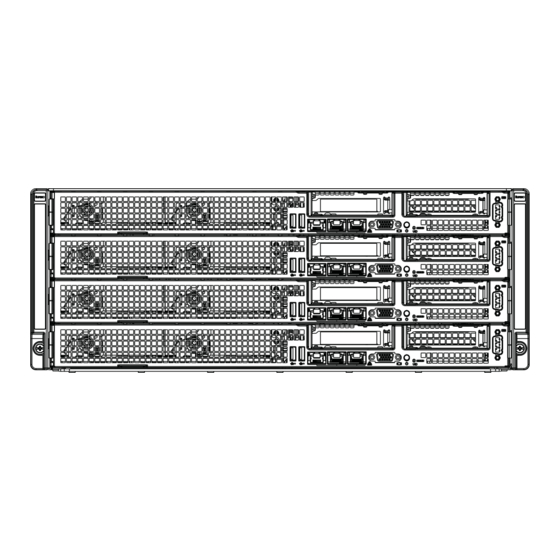
FatTwin F617H6-FT+/FTPT+ USER'S MANUAL Figure 6-1. Front and Rear Chassis Views USB Ports VGA Port Control Panel IPMI LAN Port Ethernet Ports Power Supply Chassis Fan Control Panel The control panel for each node is located on the front of the chassis. The LEDs inform you of system status. -
Page 89: Removing The Power Cord
Chapter 6: Advanced Chassis Setup Removing the Power Cord Before performing any setup or maintenance on the chassis, use the following procedure to ensure that power has been removed disconnected from the system. Removing the Power Cord 1. Use the operating system to power down the system, following the on-screen prompts. -
Page 90: Removing The Node Cover
FatTwin F617H6-FT+/FTPT+ USER'S MANUAL Removing the Node Cover Each node has a removable cover which will permit access to the nodes compo- nents. Removing the Node Cover 1. Remove the power cord from the rear of the node as described in Section 6-3 and remove the node from the chassis as described in Section 6-4. -
Page 91: Installing And Removing Hard Drives
Chapter 6: Advanced Chassis Setup Installing and Removing Hard Drives The F414IS chassis contains individual motherboards in separate 1U nodes. Each motherboard node controls the hard drives contained within that node. Note that if a node is pulled out of the chassis, the hard drives associated with that node will power down as well. -
Page 92: Replacing Fixed 3.5" Hard Drives
FatTwin F617H6-FT+/FTPT+ USER'S MANUAL Replacing Fixed 3.5" Hard Drives Replacing a Fixed 3.5" Hard Drive 1. Power down the node with the operating system and remove the cord from the rear of the power supply as described in Section 6-3. Remove the node from the chassis as described in Section 6-4. -
Page 93: Node Confi Guration
Chapter 6: Advanced Chassis Setup Node Confi guration The four F414IS chassis nodes are confi gured as illustrated above. In addition to the node components shown, there are eight exhaust fans and two power supplies located in the rear of the chassis body. Figure 6-5: Confi... -
Page 94: Removing And Installing The Backplane
FatTwin F617H6-FT+/FTPT+ USER'S MANUAL Removing and Installing the Backplane The F414IS backplane is located under the hard drives on the front left side of each node as shown in Figure 6-5. Although backplane failure rarely occurs, in the event of a backplane failure, follow the instructions below. Removing the Backplane Removing the Backplane from the Node 1. - Page 95 Chapter 6: Advanced Chassis Setup 5. Remove the three screws securing the backplane to the protection cover. Figure 6-7: Removing the Backplane from the Protection Cover 6. Install a replacement backplane onto the protection cover and secure with the screws previously set aside. 7.
-
Page 96: Power Adapter Board Replacement
FatTwin F617H6-FT+/FTPT+ USER'S MANUAL Power Adapter Board Replacement Each of the nodes includes a power adapter board, which connects it to the chassis. In the unlikely event of a failure of the power adapter board, replacement is simple and requires only a Phillips head screwdriver. Changing the Power Adapter Board 1. -
Page 97: 6-10 Installing The Motherboard
Chapter 6: Advanced Chassis Setup 6-10 Installing the Motherboard Compatible Motherboards For the most up-to-date information on compatible motherboards and other parts, visit the Supermicro Web site at www.supermicro.com. Permanent and Optional Standoffs Standoffs prevent short circuits by creating space between the motherboard and the fl... - Page 98 FatTwin F617H6-FT+/FTPT+ USER'S MANUAL Installing the Motherboard 1. Review the documentation that came with your motherboard. Become familiar with component placement, requirements, cautions, and cable connections. 1. Power down the node with the operating system and remove the cord from the rear of the power supply as described in Section 6-3.
-
Page 99: 6-11 Installing Expansion Cards
Chapter 6: Advanced Chassis Setup 6-11 Installing Expansion Cards PCIE Slot Setup The nodes of some F414IS chassis models support two low-profi le expansion cards. To install a low-profi le expansion cards follow the instructions on the following pages. Figure 6-11: PCIE Slot Shield Confi guration Low-Profi... -
Page 100: Installing A Low-Profi Le Expansion Card
FatTwin F617H6-FT+/FTPT+ USER'S MANUAL Installing a Low-Profi le Expansion Card The F414IS chassis supports two low-profi le expansion cards in each of the four nodes for a total of eight expansion cards in the chassis, Each expansion card connects to the motherboard with a riser card. Installing a Low-Profi... -
Page 101: Installation Complete
Chapter 6: Advanced Chassis Setup Figure 6-12: Removing the Riser Card Bracket from the Node Installation Complete In most cases, the node power supplies and fans are pre-installed. If you need to install fans or power supplies, continue to the Systems Fan and Power Supply sections of this chapter. -
Page 102: 6-12 Replacing Exhaust Fans
FatTwin F617H6-FT+/FTPT+ USER'S MANUAL 6-12 Replacing Exhaust Fans Eight rear exhaust fans provide cooling for the nodes in the F414IS chassis. These fans circulate air through the nodes as a means of lowering the internal temperature. The F414IS exhaust fans are easily removed from the chassis withouthat tools. There is no need to uninstall any other parts when replacing fans Replacing an Exhaust Fan 1. - Page 103 Chapter 6: Advanced Chassis Setup Figure 6-14: Removing the System Fans from the Fan Housing Squeeze the Release Tabs 6-17...
-
Page 104: 6-13 Replacing The Power Supply
FatTwin F617H6-FT+/FTPT+ USER'S MANUAL 6-13 Replacing the Power Supply The F414IS chassis includes two1620 Watt power supplies. This power supply is auto-switching capable. This enables it to automatically sense and operate at a 100v to 240v input voltage. An amber light will be illuminated on the power supply when the power is off. -
Page 105: Power Supply Replacement
Chapter 6: Advanced Chassis Setup Power Supply Replacement The F414IS chassis utilizes two redundant power supplies. In the unlikely event that the power supply unit needs to be replaced, one power supply can be removed, without powering down the system. Replacement units can be ordered directly from Supermicro (See the contact information in the Preface of this manual). - Page 106 FatTwin F617H6-FT+/FTPT+ USER'S MANUAL Notes 6-20...
-
Page 107: Chapter 7 Bios
Chapter 7: BIOS Chapter 7 BIOS Introduction This chapter describes the AMI BIOS Setup utility for the X9DRFF-7+/7T+. It also provides the instructions on how to navigate the AMI BIOS Setup utility screens. The AMI ROM BIOS is stored in a Flash EEPROM and can be easily updated. Starting BIOS Setup Utility To enter the AMI BIOS Setup utility screens, press the <Del>... -
Page 108: Starting The Setup Utility
FatTwin F617H6-FT+/FTPT+ USER'S MANUAL Starting the Setup Utility Normally, the only visible Power-On Self-Test (POST) routine is the memory test. As the memory is being tested, press the <Delete> key to enter the main menu of the AMI BIOS Setup utility. From the main menu, you can access the other setup screens. -
Page 109: Advanced Setup Confi Gurations
Chapter 7: BIOS Supermicro X9DRFF-i/7 (T)+ Version This item displays the SMC version of the BIOS ROM used in this system. Build Date This item displays the date that the BIOS ROM was built. Memory Information Total Memory This displays the amount of memory that is available in the system. Advanced Setup Confi... - Page 110 FatTwin F617H6-FT+/FTPT+ USER'S MANUAL AddOn ROM Display Mode Use this item to set the display mode for the Option ROM. Select Keep Current to use the current AddOn ROM Display setting. Select Force BIOS to use the Option ROM display mode set by the system BIOS. The options are Keep Current and Force BIOS.
- Page 111 Chapter 7: BIOS Restore on AC Power Loss Use this feature to set the power state after a power outage. Select Stay Off for the system power to remain off after a power loss. Select Power On for the system power to be turned on after a power loss.
- Page 112 FatTwin F617H6-FT+/FTPT+ USER'S MANUAL Clock Spread Spectrum Select Enable to enable Clock Spectrum support, which will allow the BIOS to monitor and attempt to reduce the level of Electromagnetic Interference caused by the components whenever needed. The options are Disabled and Enabled. RTID (Record Types IDs) This feature displays the total number of Record Type IDs for local and remote pools.
- Page 113 Chapter 7: BIOS DCU Streamer Prefetcher (Available when supported by the CPU) Select Enabled to support Data Cache Unit (DCU) prefetch of L1 data to speed up data accessing and processing in the DCU to enhance CPU performance. The options are Disabled and Enabled. DCU IP Prefetcher Select Enabled for DCU (Data Cache Unit) IP Prefetcher support, which will prefetch IP addresses to improve network connectivity and system performance.
- Page 114 FatTwin F617H6-FT+/FTPT+ USER'S MANUAL CPU C3 Report (Available when Power Technology is set to Custom) Select Enabled to allow the BIOS to report the CPU C3 State (ACPI C2) to the operating system. During the CPU C3 State, the CPU clock generator is turned off.
- Page 115 Chapter 7: BIOS Recommended Short Duration Power Limit This item displays the short duration power settings (in watts) recommended by the manufacturer. Short Duration Power Limit During Turbo Mode, the system may exceed the processors default power setting and exceed the Short Duration Power limit. By increasing this value, the processor can provide better performance for short duration.
- Page 116 FatTwin F617H6-FT+/FTPT+ USER'S MANUAL IIO 1 PCIe Port Bifurcation Control This submenu confi gures the following IO PCIe Port Bifurcation Control settings for IIO 1 PCIe ports to determine how the available PCI-Express lanes to be distributed between the PCI-Exp. Root Ports. i350/X540 Link Speed Select GEN1 to enable Generation 1 support for this port.
- Page 117 Chapter 7: BIOS CPU2 SLOT4 Link Speed Select GEN1 to enable Generation 1 support for this port. Select GEN2 to enable Generation 2 support for this port. Select GEN3 to enable Generation 3 support. The options are GEN1, GEN2, and GEN3. IOU2_2-PCIe Port This feature allows the user to set the PCI-Exp bus speed between IOU3 and PCI-e port.
- Page 118 FatTwin F617H6-FT+/FTPT+ USER'S MANUAL QPI Link Frequency Select Use this feature to select the desired QPI frequency. The options are Auto, 6.4 GT/s, 7.2 GT/s, and 8.0 GT/s. DIMM Confi guration This section displays the following DIMM information. Current Memory Mode This item displays the current memory mode.
- Page 119 Chapter 7: BIOS DDR Speed Use this feature to force a DDR3 memory module to run at a frequency other than what is specifi ed in the specifi cation. The options are Force DDR3-800, Force DDR3-1066, Force DDR3-1333, Force DDR3-1600 and Force SPD, and Auto.
- Page 120 FatTwin F617H6-FT+/FTPT+ USER'S MANUAL Thermal Throttling Throttling improves reliability and reduces power consumption in the processor via automatic voltage control during processor idle states. The options are Disabled and CLTT (Closed Loop Thermal Throttling). South Bridge This feature allows the user to confi gure the settings for the Intel PCH chip. PCH Information This feature displays the following PCH information.
- Page 121 Chapter 7: BIOS SATA Confi guration When this submenu is selected, the AMI BIOS automatically detects the presence of IDE or SATA devices and displays the following items. SATA Port0~SATA Port5: The AMI BIOS displays the status of each SATA port as detected by the BIOS.
- Page 122 FatTwin F617H6-FT+/FTPT+ USER'S MANUAL RAID Mode The following items are displayed when RAID Mode is selected: SATA RAID Option ROM/UEFI Driver Use this feature to enable the onboard SATA Option ROM or EFI driver. The options are Disabled and Enabled.. Port 0~5 Hot Plug Select Enabled to enable hot-plug support for the particular port.
- Page 123 Chapter 7: BIOS SERR# Generation Select Enabled to allow a PCI device to generate an SERR number for a PCI Bus Signal Error Event. The options are Enabled and Disabled. Maximum Payload Select Auto to allow the system BIOS to automatically set the maximum payload value for a PCI-E device to enhance system performance.
- Page 124 FatTwin F617H6-FT+/FTPT+ USER'S MANUAL VGA Priority This feature allows the user to select the graphics adapter to be used as the primary boot device. The options are Onboard, and Offboard. Network Stack Select Enabled enable PXE (Preboot Execution Environment) or UEFI (Unifi ed Extensible Firmware Interface) for network stack support.
- Page 125 Chapter 7: BIOS SOL Confi guration Serial Port Select Enabled to enable the SOL serial port. The options are Enabled and Disabled. Device Settings This item displays the settings of the SOL serial port. SOL Change Settings This option specifi es the base I/O port address and the Interrupt Request address of the SOL Port.
- Page 126 FatTwin F617H6-FT+/FTPT+ USER'S MANUAL Terminal Type This feature allows the user to select the target terminal emulation type for Console Redirection. Select VT100 to use the ASCII Character set. Select VT100+ to add color and function key support. Select ANSI to use the Extended ASCII Character Set.
- Page 127 Chapter 7: BIOS Recorder Mode Select Enabled to capture the data displayed on a terminal and send it as text messages to a remote server. The options are Disabled and Enabled. Resolution 100x31 Select Enabled for extended-terminal resolution support. The options are Disabled and Enabled.
- Page 128 FatTwin F617H6-FT+/FTPT+ USER'S MANUAL Terminal Type This feature allows the user to select the target terminal emulation type for Console Redirection. Select VT100 to use the ASCII character set. Select VT100+ to add color and function key support. Select ANSI to use the extended ASCII character set.
- Page 129 Chapter 7: BIOS High Precision Event Timer Select Enabled to activate the High Precision Event Timer (HPET) that produces periodic interrupts at a much higher frequency than a Real-time Clock (RTC) does in synchronizing multimedia streams, providing smooth playback, reducing the dependency on other timestamp calculation devices, such as an x86 RDTSC Instruction embedded in the CPU.
-
Page 130: Event Logs
FatTwin F617H6-FT+/FTPT+ USER'S MANUAL Event Logs Select the Event Logs tab to access the following submenu items. Change SMBIOS Event Log Settings This feature allows the user to confi gure SMBIOS Event settings. Enabling/Disabling Options SMBIOS Event Log Select Enabled to enable SMBIOS (System Management BIOS) Event Logging during system boot. - Page 131 Chapter 7: BIOS Erase Event Log Select Enabled to erase the SMBIOS (System Management BIOS) Event Log, which is completed before a event logging is initialized upon system reboot. The options are No, Yes, Next reset, and Yes, Every reset. When Log is Full Select Erase Immediately to immediately erase SMBIOS error event logs that exceed the limit when the SMBIOS event log is full.
-
Page 132: Ipmi
FatTwin F617H6-FT+/FTPT+ USER'S MANUAL IPMI Select the IPMI (Intelligent Platform Management Interface) tab to access the following submenu items. IPMI Firmware Revision This item indicates the IPMI fi rmware revision used in your system. IPMI Status This item indicates the status of the IPMI fi rmware installed in your system. ... - Page 133 Chapter 7: BIOS When SEL is Full This feature allows the user to decide what the BIOS should do when the system event log is full. Select Erase Immediately to erase all events in the log when the system event log is full. The options are Do Nothing and Erase Immediately. ...
-
Page 134: Boot
FatTwin F617H6-FT+/FTPT+ USER'S MANUAL Boot This submenu allows the user to confi gure the following boot settings for the system. Set Boot Priority 1st Boot Device, 2nd Boot Device, etc. Use this feature to specify the sequence of boot device priority. ... -
Page 135: Security
Chapter 7: BIOS Security This menu allows the user to confi gure the following security settings for the system. Password Check Use this feature to determine when a password entry is required. Select Setup to require the password only when entering setup. Select Always to require the password when entering setup and on each boot. -
Page 136: Save & Exit
FatTwin F617H6-FT+/FTPT+ USER'S MANUAL Save & Exit This submenu allows the user to confi gure the Save and Exit settings for the system. Discard Changes and Exit Select this option to quit the BIOS Setup without making any permanent changes to the system confi... - Page 137 Chapter 7: BIOS Discard Changes Select this feature and press <Enter> to discard all the changes and return to the BIOS setup. When the dialog box appears, asking you if you want to load previous values, select Yes to load the values previous saved, or select No to keep the changes you've made so far.
- Page 138 FatTwin F617H6-FT+/FTPT+ USER'S MANUAL Notes 7-32...
-
Page 139: Appendix A Bios Error Beep Codes
Appendix A: BIOS Error Beep Codes Appendix A BIOS Error Beep Codes During the POST (Power-On Self-Test) routines, which are performed each time the system is powered on, errors may occur. Non-fatal errors are those which, in most cases, allow the system to continue the boot-up process. - Page 140 FatTwin F617H6-FT+/FTPT+ USER'S MANUAL Notes...
-
Page 141: Appendix B System Specifi Cations
Appendix B: System Specifi cations Appendix B System Specifi cations Note: Unless noted specifi cations apply to a complete system (all serverboards). There are four motherboard drawer nodes per system. Processors Two E5-2600 series series processors per node in Socket R LGA 2011 type sockets Note: please refer to our website for details on supported processors. - Page 142 FatTwin F617H6-FT+/FTPT+ USER'S MANUAL Serverboard FatTwin X9DRFF-7+/7T+ serverboard (proprietary form factor) Dimensions: (LxW) 18.72" x 8.54" (475.49 mm x 216.92 mm) Chassis F414IS-R1K62B (4U rackmount) Dimensions: (WxHxD) 17.63 x 6.96 x 35 in. (448 x 177 x 889 mm) Weight Gross (Bare Bone): 240 lbs (108.86 kg) System Cooling The system has eight (8) 8-cm PWM system cooling fans in the rear of the...
- Page 143 Appendix B: System Specifi cations The table below specifi es the preferred ambient temperature versus processor support for the FatTwin F617H6-FT+/FTPT+ system. Ambient Temperature versus Porcessor Support 35°C 30°C 25°C 135 W 130 W 115 W 6,7,9 8,10 95 W 1,11 4,13 80 W...
- Page 144 FatTwin F617H6-FT+/FTPT+ USER'S MANUAL Regulatory Compliance Electromagnetic Emissions: FCC Class A, EN 55022 Class A, EN 61000-3-2/-3- 3, CISPR 22 Class A Electromagnetic Immunity: EN 55024/CISPR 24, (EN 61000-4-2, EN 61000-4-3, EN 61000-4-4, EN 61000-4-5, EN 61000-4-6, EN 61000-4-8, EN 61000-4-11) Safety: CSA/EN/IEC/UL 60950-1 Compliant, UL or CSA Listed (USA and Canada), CE Marking (Europe) California Best Management Practices Regulations for Perchlorate Materials:...
Need help?
Do you have a question about the FatTwin F617H6-FT+ and is the answer not in the manual?
Questions and answers