OM POWER OM2000+ Manual
Shortwave plus 50mhz
Hide thumbs
Also See for OM2000+:
- Manual (38 pages) ,
- User manual (35 pages) ,
- Tuning procedure and part list (12 pages)
Table of Contents
Advertisement
Quick Links
Download this manual
See also:
User Manual
Advertisement
Table of Contents

Related Manuals for OM POWER OM2000+


Summary of Contents for OM POWER OM2000+
- Page 1 OM2000+ MADE I N S LOVAKIA SHORTWAVE P LUS 5 0 M Hz POWER A MPLIFIER WWW.OM-‐POWER.COM OM P OWER, s .r.o. 9 3030 B áč 1 26, SLOVAKIA ...
-
Page 2: Table Of Contents
TABLE OF CONTENTS 1. GENERAL I NFORMATION .............. 3 2.1. Introduction …………………………………………………………………. 3 2.2. Specification …………………………………………………………………. 3 2 .2.1. P arameters …………………………………………………………………. ... - Page 3 6.2. Fuse R eplacement …………………………………………………………………. 30 6.3. Tube R eplacement …………………………………………………………………. 30 6.4. Cleaning …………………………………………………………………. 30 7. APPENDIX …………………………………………………………………. ...
-
Page 4: General I Nformation
1. GENERAL I NFORMATION 1.1. Introduction T he OM Power model OM2000+ is designed for all short wave amateur bands from 1.8 to 29.7 MHz ... -
Page 5: Indicators
Screen v oltage e rror • Grid c urrent t oo h igh • Grid v oltage e rror • Heating v oltage e rror • Mistuning o f P A •... -
Page 6: Safety Instructions
SAFETY INSTRUCTIONS WARNING! DANGEROUS H IGH V OLTAGE I NSIDE! The p ower a mplifier i s u sing h igh v oltage u p t o 3000V D C, w hich i s v ery d angerous f or h uman l ife! Read ... -
Page 7: General Description
CAUTION The a mplifier m ust b e i nstalled i n s uch a w ay t hat f ree f low o f h ot a ir f rom t he t ube i s a llowed. T he amplifier ... -
Page 8: Power S Upply
The output of the amplifier is a Pi-‐L circuit. The ceramic capacitor for TUNE and LOAD are divided. This e nables t he a mplifier t o b e t uned e xactly a nd m akes i t p ossible t o e asily r eturn t o t he p reviously set ... -
Page 9: Safety D Evices
3 kVA toroidal transformer is visible on the left side. Switch-‐ON board is in the front, Power s upply b oard b ehind i t. ... -
Page 10: Grounding
4.1. Grounding CAUTION The a mplifier h as t o b e g rounded p roperly! C onnect t he s crew o n t he r ear p anel o f t he a mplifier t o 2 ... -
Page 11: Main S Upply
CAUTION If y ou a re u sing a n o lder t ransceiver o r t ransmitters w ithout t ime d elay, w e r ecommend t o c onnect the PA in such a way that the transmit/receive switch (foot switch for example) is connected with ... -
Page 12: Operation
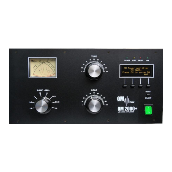
OPERATION WARNING! Before switching PA on, make sure that amplifier is grounded, antenna or dummy load is connected, a nd l ine c ord i s p utted t o t he o utlet. B e s ure y ou s elected A C i nput b y 7 .1. ... - Page 13 BAND -‐ B and s elector s witch TUNE -‐ ...
-
Page 14: Preparation F Or O Peration
ON A IR -‐ T ransmitting m ode L ED STBY -‐ S tandby m ode L ED ... -
Page 15: Display M Enu
If y ou c hange D SP d uring w arming t ime, y ou l ost c ount d own i nformation. P ress B ACK ( S1) t o r estore starting ... - Page 16 After pressing MENU (S2) S1–S4 buttons changed their functions. To edit display parameters, p ress D ISP b utton. ...
-
Page 17: Settings M Enu
S2 a nd S 3 n ow c hanged t heir f unctions. To edit left side of the second line, press LEFT ... - Page 18 Electronic B ias S ettings ( EBS) i s o ne o f s ignificant f eature o f t he p ower a mplifier. I t a llows t o s et l ow plate ...
-
Page 19: Service M Enu
If you wish to restore factory default parameters, use UP or DOWN button to select Restore default parameters. Then press ... - Page 20 Use Service menu after replacing the tube. This i s s tep N o. 1 . To e nter S ervice m enu, g o t o t he M ENU f irst, then ...
- Page 21 Use U P o r D OWN b utton t o s elect W arnings. Press ENT to see warning numbers or letters (see t he t able i n c hapter 6 ). ...
-
Page 22: Operation M Ode
Use UP or DOWN to select Calibration Ip & Is. P ress E NT t o d o i t. ... - Page 23 Check all connections again. Set BAND selector, TUNE and LOAD capacitors according to TCVR parameters and delivered tuning table (see next part for more details). Apply low input power and press PTT. Check Analog wattmeter first. Try to tune PA for maximum output power and minimum SWR.
-
Page 24: Tuning O F T He P Ower A Mplifier
5.4. Tuning o f t he P ower A mplifier The OM2000+ power amplifier is operated in class AB. Thus it’s possible to obtain a maximum output power at excellent linearity. For this purpose the amplifier has to be tuned carefully ... - Page 25 Press OPER to enter operation mode. Apply low input power and press PTT. Be sure you selected right B AND, T UNE a nd L OAD k nob p ositions. I f y ou m ade s ome m istake, f ault m essage a ppears: ...
- Page 26 Two of important information is visible – screen current increased, but still is within the allowed limits. Turn LOAD knob slightly in arrows direction to get TUNE indicator between ...
- Page 27 To s tart t he s econd m ethod o f f ine t uning, p ress S 2 ( TUNE) b utton i n O PER m ode. ...
-
Page 28: Maintenance
MAINTENANCE 6.1. I ndication o f F ault C onditions If a f ault c ondition a ppears d uring t he o peration o f t he a mplifier, t he s afety c ircuits o f O M2000+ w ill react. There are several warning or fault messages possible to appear on the display, when some of ... - Page 29 rest of them one position back. It means that every time last 30 messages are visible on the display. Next t able s hows l imited v alues f or t he s afety c ircuits a ctivation. ...
- Page 30 An e xample s hows s ituation w hen I nput power i s t oo h igh. B y p ressing P TT s afety circuit ...
-
Page 31: Fuse R Eplacement
In the case of some hardware failure or if your power amplifier is not working properly, please contact t he m anufacturer o r y our d ealer. ... -
Page 32: Appendix
APPENDIX 7.1. Primary A C v oltage s election Primary s ection o f t he H V t ransformer i s s witchable f or t hree v alues o f A C v oltage ( 220, 2 30, 2 40V). Factory ... -
Page 33: Removing T He H V T Ransformer
Remove the upper lid first. On the right side of the PA, next to the HV transformer there are two PCBs ... - Page 34 Weight distributed (transformer has 12 kg, rest of the PA has cca 12 too). When refitting the transformer, watch to the correct location of individual sections and wires. NOTE Manufacturer reserves the right to make future changes in the way of connecting the transformer to the board.
-
Page 35: Block D Iagram O F T He O M2000+ P Ower A Mplifier
7.3. Block D iagram o f O M2000+ P ower A mplifier 34 ...
Need help?
Do you have a question about the OM2000+ and is the answer not in the manual?
Questions and answers