OM POWER OM2000+ User Manual
Shortwave plus 50 mhz
Hide thumbs
Also See for OM2000+:
- Manual (38 pages) ,
- User manual (35 pages) ,
- Tuning procedure and part list (12 pages)

Related Manuals for OM POWER OM2000+


Summary of Contents for OM POWER OM2000+
- Page 1 OM2000+ MADE IN SLOVAKIA SHORTWAVE PLUS 50 MHz POWER AMPLIFIER WWW.OM-POWER.COM OM POWER, s.r.o. 93030 Báč 126, SLOVAKIA Contact : +421 905 321 410 e-mail : om-power@om-power.com...
-
Page 2: Table Of Contents
TABLE OF CONTENTS 1. GENERAL INFORMATION ..............2.1. Introduction …………………………………………………………………. 2.2. Specification …………………………………………………………………. 2.2.1. Parameters …………………………………………………………………. 2.2.2. Protection Circuits …………………………………………………………………. 2.2.3. Indicators …………………………………………………………………. 2.2.4. Features …………………………………………………………………. 2. SAFETY INSTRUCTIONS …………………………………………………………………. 3. GENERAL DESCRIPTION …………………………………………………………………. 3.1. HF part …………………………………………………………………. 3.2. Power Supply …………………………………………………………………. - Page 3 6.2. Fuse Replacement …………………………………………………………………. 6.3. Tube Replacement …………………………………………………………………. 6.4. Cleaning …………………………………………………………………. 7. APPENDIX …………………………………………………………………. 7.1. Primary AC selection …………………………………………………………………. 7.2. Removing the HV Transformer ……………………………………………………. 7.3. Block Diagram of the OM2000+ Power Amplifier …………………………...
-
Page 4: General Information
1. GENERAL INFORMATION 1.1. Introduction he OM Power model OM2000+ is designed for all short wave amateur bands from 1.8 to 29.7 MHz (including WARC bands) plus 50 MHZ and all modes. It is equipped with a ceramic tetrode FU-728F. -
Page 5: Indicators
Screen voltage error Grid current too high Grid voltage error Heating voltage error Mistuning of PA Temperature to high Soft start for fuses protection “switch-on blocking “ at opened amplifier 1.2.3. Indicators Number of indicators visible on the front panel will inform you about value of some parameters or operation status: OLED display... -
Page 6: Safety Instructions
SAFETY INSTRUCTIONS WARNING! DANGEROUS HIGH VOLTAGE INSIDE! The power amplifier is using high voltage up to 3000V DC, which is very dangerous for human life! Read next safety instructions carefully first, before you will start to install and operate power amplifier! NEVER VIOLATE NEXT RULES! WARNING! NEVER ALLOW CHILDREN to play around PA or to touch power amplifier or connected cables in... -
Page 7: General Description
CAUTION The amplifier must be installed in such a way that free flow of hot air from the tube is allowed. The amplifier must not be installed in a constrained surrounding (i.e. tight shelves etc.). During long time operation ventilation grid can reach high temperature. Do not touch it! CAUTION The amplifier must be properly grounded during operation CAUTION... -
Page 8: Power Supply
The output of the amplifier is a Pi-L circuit. The ceramic capacitor for TUNE and LOAD are divided. This enables the amplifier to be tuned exactly and makes it possible to easily return to the previously set positions after band changes. Top view on the opened OM2000+ Tetrode FU728F Antenna Switch... -
Page 9: Safety Devices
Type of supported TCVR and working 3 kVA toroidal transformer is visible on the left frequency are visible on the display. side. Switch-ON board is in the front, Power supply board behind it. AUTO LED is ON. CAUTION Primary section of the transformer is switchable for 220 - 240 VAC. Factory setting is 230VAC. If the AC voltage in your network is 220 or 240 Volts, you need to set the correct value before first starting of the PA. -
Page 10: Grounding
4.1. Grounding CAUTION The amplifier has to be grounded properly! Connect the screw on the rear panel of the amplifier to your local grounding system with a copper cable; use a cross-section of 4 mm at least. Connect your transceiver to the same grounding system of your shack carefully! Use minimum length cables and make certain that the connections are both physically and electrically sound. -
Page 11: Main Supply
CAUTION If you are using an older transceiver or transmitters without time delay, we recommend to connect the PA in such a way that the transmit/receive switch (foot switch for example) is connected with the KEY IN socket of the amplifier. The KEY OUT socket is to be connected with the PTT socket at the transceiver. -
Page 12: Operation
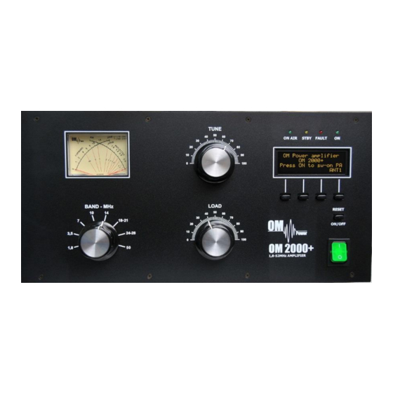
OPERATION WARNING! Before switching PA on, make sure that amplifier is grounded, antenna or dummy load is connected, and line cord is putted to the outlet. Be sure you selected AC input by 7.1. CAUTION Before switching PA on, check all connections between PA and TCVR. CAUTION Do not turn PA on for at least 2 hours after unpacking it and locating in its operating location. - Page 13 BAND Band selector switch TUNE Anode capacitor for tuning (higher frequencies to "0"; lower frequencies to „100“). LOAD Output capacitor tunes antenna load resistance to the amplifier. Capacity is low at „100“ and high at "0" on the scale. TUNE LED Three LEDs assists in tuning the amplifier WATMETER - Analog double system meter for forward and reflected power measuring...
-
Page 14: Preparation For Operation
ON AIR - Transmitting mode LED STBY - Standby mode LED FAULT - Failure LED - PA is „ON“ LED - OPER / STBY - Press to switch between Standby and Operation mode - Return to the previous level - MENU - Enter the Menu DOWN - Scroll down... -
Page 15: Display Menu
If you change DSP during warming time, you lost count down information. Press BACK (S1) to restore starting message. When warming time expires, PA switches Type of supported TCVR and working itself automatically to the STBY mode. frequency are visible on the display. You have two possibilities now - switch PA to OPER mode and start operation, OR to go AUTO LED is ON. - Page 16 After pressing MENU (S2) S1–S4 buttons changed their functions. To edit display Type of supported TCVR and working parameters, press DISP button. frequency are visible on the display. AUTO LED is ON. Press DIS1 to edit first display. Type of supported TCVR and working frequency are visible on the display.
-
Page 17: Settings Menu
S2 and S3 now changed their functions. To edit left side of the second line, press LEFT Type of supported TCVR and working button. frequency are visible on the display. AUTO LED is ON. Go UP or DOWN to select desired parameter. Press ENT to confirm selection. - Page 18 Electronic Bias Settings (EBS) is one of significant feature of the power amplifier. It allows to set low plate current after pressing the PTT regardless of whether you have CW or SSB mode, until RF signal is no present at the input. At the moment when RF signal comes to the input of PA, bias will automatically change to its working value.
- Page 19 If you wish to restore factory default parameters, use UP or DOWN button to select Restore default parameters. Then press Type of supported TCVR and working ENT. frequency are visible on the display. AUTO LED is ON. Press YES for 1 second to confirm restoring. Type of supported TCVR and working frequency are visible on the display.
-
Page 20: Service Menu
Use UP or DOWN button to set second mode. The fan will activate together with PTT. Type of supported TCVR and working Press ENT to confirm settings. frequency are visible on the display. AUTO LED is ON. Use UP or DOWN button to set the third mode. - Page 21 Use UP or DOWN button to select Time ON parameter. Press ENT to see total operating Type of supported TCVR and working hours of the PA. frequency are visible on the display. AUTO LED is ON. Press ESC to go back to the Service menu. Type of supported TCVR and working frequency are visible on the display.
- Page 22 Use this procedure after replacing the tube. This is step No. 2. Type of supported TCVR and working Scroll UP or DOWN to select EBS1 settings. Press ENT to start automatic adjustment of frequency are visible on the display. EBS1 (20 mA). AUTO LED is ON.
-
Page 23: Operation Mode
5.3. Operation mode CAUTION In STBY the amplifier is in bypass-mode and your transceiver is directly connected to the antenna. Maximum allowed power in bypass mode is 100 Watts! Passing RF power is measured with analog wattmeter only. It is not displayed if PA is either in standby mode or turned OFF. Press OPER to activate operation mode. -
Page 24: Tuning Of The Power Amplifier
Using foot switch in „KEY IN” we Type of supported TCVR and working activated transmitting mode of the PA first. frequency are visible on the display. “ON AIR” LED is ON. EBS is active (Ip = 20mA) AUTO LED is ON. In the transmitting mode all 4 buttons (S1, S2, S3, and S4) are blocked! Type of supported TCVR and working... - Page 25 A tuning table is delivered with the power amplifier. For coarse tuning select a band with BAND switch and choose the setting of “TUNE” and “LOAD” capacitors according to the table. Band (MHz) Tune Load Input PWR (W) Output PWR (W) 1.845 2000 3.630...
- Page 26 Another mistake can occur, if you have antenna connected to the wrong output. In such a case „SWR is too high“ error message appears. Change antenna output using S4 button. This is not an optimal result, TUNE indicator must go between both arrows. Use TUNE knob to get maximum output power and Type of supported TCVR and working LOAD knob to get indicator between...
- Page 27 Remember Always use TUNE knob to get maximum output power. Use LOAD knob to get TUNE indicator on the display to the middle position between both arrows. Simultaneously check if Is graph indicator stays within the boundaries. Repeat both steps more times. Proper operation mode of FU-728F requires the plate voltage to be close to 3 kV.
-
Page 28: Maintenance
Display shows properly tuned PA. TUNE indicator is in the middle, Screen current is higher, but still inside the limits. Type of supported TCVR and working After proper fine tuning release PTT and press STOP button. PA is now prepared for operation. frequency are visible on the display. - Page 29 Power Out is too high Refl. power too high Power In is too high Low output power (tune) Plate current too high Grid current is high Screen current error Heating voltage error HARD FAULT Plate voltage error Grid voltage is low Screen voltage error SWR is too high Amplifier is too hot...
- Page 30 Plate current is too high 1.8A 2.0A Grid current is too high 10mA 20mA Screen current is too high 50mA 60mA Heating voltage error +/- 2V *** +/- 2.5V HARD FAULT (from 3.1 version) Plate current >2.5A **** Plate voltage error Min.
- Page 31 WARNING! Never try to change or move any part inside the amplifier except of tube or fuses. Substitution of parts may void intrinsic safety! Manufacturer’s contacts: OM POWER, s.r.o. 930 30 Báč 126 SLOVAKIA Email: om-power@om-power.com...
-
Page 32: Fuse Replacement
6.2. Fuse Replacement The user is allowed to change mains fuses (6.3 x 32mm), accessible from the rear panel, only. In the case of fuse (fuses) interruption inside the power amplifier, exchange can be carried out only by professionally qualified person! Internal fuses are located mainly on the SWITCH-on board (next to the HV transformer). -
Page 33: Appendix
APPENDIX 7.1. Primary AC voltage selection Primary section of the HV transformer is switchable for three values of AC voltage (220, 230, 240V). Factory settings is 230VAC. Before first starting of the PA we recommend to check the correct value according to the AC voltage in your network. -
Page 34: Removing The Hv Transformer
NOTE AC selector range can be changed in the production according to the specific conditions in individual countries. 7.2. Removing HV Transformer For simpler and easier transport of the PA, HV transformer can be removed and taken separately. This distributes the weight of the PA (24 kg) about half and half. Follow next steps to do it. 1.
Need help?
Do you have a question about the OM2000+ and is the answer not in the manual?
Questions and answers