
Related Manuals for OM POWER OM2501HF


Summary of Contents for OM POWER OM2501HF
- Page 1 MADE IN SLOVAKIA OM2501HF ( OM3501HF) SHORTWAVE POWER AMPLIFIER WWW.OM-POWER.COM OM Power, s.r.o. 93030 Báč 126, SLOVAKIA Contact : +421 905 321 410 e-mail : om-power@om-power.com e-mail : om-power@om-power.com...
-
Page 2: Table Of Contents
Grounding ……………….…………………………………………….. 4.2. Coaxial Cable …………………………………………………………….. 4.3. Control Cable ……………………………………………………………... 4.4. Cooling ……………………………………………………………... 5. OPERATION …………………………………………………………..…. 5.1. OM2501HF Front Panel ………………………………………………………….…. 5.2. OM2501HF Control …………………………………………………………..… 5.3. Preparing for operation …………………………………………………………..… 5.4. Operation mode ………………………………………………………….…. 6. MAINTENANCE ………………………………………………………….…. 6.1. Indication of Fault Conditions …………………………………………………………….. - Page 3 6.4. Cleaning ………………………………………………………….…. 7. APPENDIX ……………………………………………………………... 7.1. Primary AC selection ……………………………………………………………... 7.2. OM2501HF firmware upgrade …………………………..…………………………………. 7.3. Control panel connectors pin-out …………………………….……………………………… 7.4. Block Diagram of the OM2501HF Power Amplifier …………..……………………. 7.5. Troubleshooting ………………………………………………………..……. 7.6. Factory reset ………………………………………………………………..
-
Page 4: General Information
1.1. Introduction he OM Power model OM2501HF and OM3501HF is designed for all shortwave amateur bands from 1.8 to 29.7 MHz (including WARC bands) and all modes. It is equipped with a ceramic tetrodes FU- 728F or GU84B (OM3501HF with GU78B). -
Page 5: Protection Circuits
1.2.2. Protection Circuits There are several protection circuits used in the amplifier. They are activated when one or more parameters exceed defined values or some unwanted condition occurs. • VSWR too high • Anode current too high • Anode voltage error •... -
Page 6: Safety Instructions
Never turn the amplifier on without the upper lid in place. DO NOT ATTEMPT TO SHORT OR BYPASS safety switch under upper lid! The OM2501HF amplifier should not be used in a WET or HUMID environment or be exposed to RAINFALL! -
Page 7: General Description
FU-728F or GU84B ( GU78B ) in a grounded-cathode circuit (input into control grid). The OM2501HF (OM3501HF) amplifier achieves excellent linearity by the voltage stabilization of the control grid bias and the screen voltage. The power input is fed to the control grid, using a broadband input circuit with an input impedance of 50 Ohms. -
Page 8: Power Supply
Top view on the opened OM2501HF (OM3501HF) Tetrode FU728F (GU84b) Blower Switch-ON Board Output Pi-L Circuit Tuning Capacitor Front subpanel Power Supply Board 3.2. Power Supply This Power amplifier uses two 2 ( 3) KVA toroidal transformer. A soft start is provided using relays and resistors (placed on the switch-ON board). -
Page 9: Safety Devices
safety resistors and fuse are employed to protect the amplifier against overload (placed on the power supply board and around PI-L circuit). The separate screen grid supply is regulated and stabilized with MOSFET circuits and delivers abt. 350V DC at 120mA. Control grid voltage is also stabilized (-120V DC). Change of stabilized first grid voltage is controlled by the software (EBS for example). -
Page 10: Grounding
4.1. Grounding The amplifier has to be grounded properly! Connect the screw on the rear panel of the amplifier to your local grounding system with a copper cable; use a cross-section of 4 mm least. Connect your transceiver to the same grounding system of your shack carefully! Use minimum length cables and make certain that the connections are both physically and electrically sound. -
Page 11: Control Cable
During transmitting the middle pin is connected to the ground. The relays of the OM2501HF (OM3501HF) have to be switched earlier than HF is applied (cold switching). Modern transceivers they have a time delay between PTT switching and power output, recommended is to set the time delay to 15ms. -
Page 12: Operation
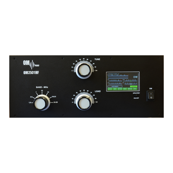
5.1. OM2501HF Front Panel Front panel of the OM2501HF containing the touch TFT display , two control switches and three knobs for output circuit adjustment. Main Switch. After turning ON, a small 12V power supply for logic, protection circuits and the display will be activated. -
Page 13: Om2501Hf Control
PA OFF. Always first use the ON/OFF button as this allows for a predetermined (software controlled) time to cool down the tube and inside the PA compartment. 5.2. OM2501HF, OM3501HF control Turn ON the green Main Power switch and the home screen lights up. Initial control touch buttons are visible on the bottom line. -
Page 14: Preparing For Operation
5.3 Preparing for operation In STBY the amplifier is in bypass-mode and your transceiver is directly connected to the antenna. Maximum allowed power in bypass mode is 200 Watts! The bypass RF power is displayed if PA is in standby mode. To turn PA ON press ON/OFF button on the front panel (black one) and hold it abt. - Page 15 Press INFO button A new button is visible – SET Umain. Press it. Type of supported TCVR and working frequency are visible on the display. AUTO LED is ON. Type in the actual setting of the primary voltage tap and press ENT. Type of supported TCVR and working Press EXIT twice to go back to the Menu frequency are visible on the display.
- Page 16 Next SETTINGS position is for display parameters. First choose the background Type of supported TCVR and color. Scroll on it and choose the color working (left/right). Press SAVE twice, then scroll to frequency are visible on the OWN CALL. display. AUTO LED is ON.
- Page 17 Next lines are for EBS (Electronic Bias Setting) Type of supported TCVR and working ON/OFF and for EBS level selection. frequency are visible on the display. We recommend EBS ON. See next comment for more details. AUTO LED is ON. Electronic Bias Settings (EBS) is a significant feature of this power amplifier.
- Page 18 Pressing MEAS displays this screen. Instantaneous values of the basic amplifier Type of supported TCVR and working parameters are displayed. frequency are visible on the display. NOTE: You can FREEZE the screen and/or allow constant monitoring. AUTO LED is ON. By pressing the SERVICE button we are in the Type of supported TCVR and working SERVICE settings mode.
- Page 19 You can try to do this manually, too. Scroll to SET EBS1 MANUAL and press SET. Use Type of supported TCVR and working up/down buttons to set 20mA or as close as frequency are visible on the display. possible value and press SAVE. Similar ways EBS2 can be preprogrammed ( 300 mA FU-728F, 400mA GU84B and 500 mA AUTO LED is ON.
-
Page 20: Operation Mode
5.4.Operation mode Before switching to operation mode, check all connections between PA and TCVR. We are now back in the Main display. We are ready to go to the operation mode. Type of supported TCVR and working Press the black STBY/OPER button on the front frequency are visible on the display. - Page 21 When the antenna impedance has greater variance from 50 Ohms, it may be the case that the PA cannot deliver the full power 2500W (3500W), or some of the protection circuits may be automatically activated. In such cases we recommend doing a manual tuning. The best indication of proper PA tuning is the Screen Current.
-
Page 22: Maintenance
If a fault condition appears during the operation of the amplifier, the safety circuits of OM2501HF(OM3501HF) will react immediately. There are several types of warning or fault messages that may appear on the display when any of the protection circuits are activated. The OM2501HF (OM3501HF) power amplifier provides the following protection: Power Out is too high Refl. - Page 23 AUTO LED is ON. Never try to change or move any part inside the amplifier except the tube or fuses. Substitution of parts may void intrinsic safety! Manufacturer’s contacts: OM POWER, s.r.o. 930 30 Báč 126 SLOVAKIA Email: om-power@om-power.co...
-
Page 24: Fuse Replacement
Internal fuses are located mainly on the SWITCH-on board (next to the HV transformer). One special fuse, filled with sand, is used in the model OM2501HF(OM3501HF). In the case of an accidental discharges or short within the tube this fuse (4 Amps fast, filled with sand) saves the HV supply circuits. - Page 25 Side view on the opened OM2501HF (OM3501HF) HV supply board AC Selector SW ON board HV Transformers Remove the upper lid first. On the right side of the PA, there are two PCBs mounted. On the right upper side is Switch ON board where AC selector is located.
-
Page 26: Om2501Hf Firmware Upgrade
OM Power website http://www.om-power.com/downloads. Store it to OM2501HF(OM3501HF) folder created on your PC. NOTE: Use a serial null modem cable and connect to the PC port on the OM2501HF(OM3501HF) rear panel with a COM port on the PC. - Page 27 Turn on the power amplifier with the black ON switch on the front panel. Type of supported TCVR and working Press INFO to enter the INFO Menu. frequency are visible on the display. AUTO LED is ON. Press UPGRADE to start the Amplifier upgrade process.
- Page 28 NOTE: Do not take any action until this screen disappears! AUTO LED is ON. At the end you will return to the main screen of OM2501HF(OM3501HF). Turn the PA OFF, disconnect the PC serial cable and you are ready to use the OM2501HF(OM3501HF) with the new firmware.
-
Page 29: Control Panel Connectors Pin-Out
7.3. Control panel (rear side) connectors pin-out PC connector DB 9 female RS232 connection to the computer. For UPRADE firmware communication connect pin 2 TX-D, pin 3 RX-D and pin 5 GROUND KEY IN – RCA connector Input signal PTT switching voltage / current 5V /2mA) KEY OUT –... -
Page 30: Block Diagram Of The Om2501Hf Power Amplifier
7.4. Block Diagram of the OM2501HF Power Amplifier... -
Page 31: Troubleshooting
7.5. Troubleshooting The OM25001HF(OM3501HF) power amplifier contains several protection circuits, which constantly monitor operation of the Amplifier. When the firmware defined parameters exceed defined operating levels, a WARNING appears in the LAST EVENTS window of the PA front panel. If some parameters exceed a defined critical level, a FAULT is activated and the PA will automatically switch to STBY mode. - Page 32 Grid voltage is low Check grid power supply Low voltage on the grid. Check fuse F9 on HV supply board. Check fuse F10 and F11 on HV supply board and fuse F1 on Screen voltage error Check screen power supply the Screen board.
-
Page 33: Factory Reset
7.6. Factory reset: In the case of very abnormal behaviour of the OM2501HF (OM3501HF) it is possible to do a factory reset. This will reset all the amplifier parameters back to the factory default values. Press and hold the ON/OFF button and press the green Main power switch for several seconds until the following display appears.
Need help?
Do you have a question about the OM2501HF and is the answer not in the manual?
Questions and answers