OM POWER OM2000+ User Manual
External radio frequency
power amplifier
Hide thumbs
Also See for OM2000+:
- Manual (38 pages) ,
- User manual (35 pages) ,
- Tuning procedure and part list (12 pages)
Table of Contents
Advertisement
Quick Links
Download this manual
See also:
Manual
!
Exhibit'6:'User's'Manual'
External)Radio)Frequency)
Power)Amplifier)OM2000+)
!
!
)
Model)2000+)
!
Array%Solutions%
2611%North%Beltline%Rd%%
Suite%109%
Sunnyvale,%Texas%75182%
USA%
Tel:%214%954%7140%
fax:%214%954%7142%
%
E-mail:
info@arraysolutions.com
Exhibit!6!!!!!!!!!!!!!!!!!!!!!!!!!!!!!!!!!!!!!!!!!!!!!!!!!!!!!!!Page!1!!from!35!
!
Advertisement
Table of Contents

Related Manuals for OM POWER OM2000+


Summary of Contents for OM POWER OM2000+
- Page 1 Exhibit'6:'User’s'Manual' External)Radio)Frequency) Power)Amplifier)OM2000+) Model)2000+) Array%Solutions% 2611%North%Beltline%Rd%% Suite%109% Sunnyvale,%Texas%75182% USA% Tel:%214%954%7140% fax:%214%954%7142% E-mail: info@arraysolutions.com Exhibit!6!!!!!!!!!!!!!!!!!!!!!!!!!!!!!!!!!!!!!!!!!!!!!!!!!!!!!!!Page!1!!from!35!
-
Page 2: Table Of Contents
TABLE%OF%CONTENTS% 1. GENERAL!INFORMATION! ..............! 2.1.! Introduction! ………………………………………………………………….! 2.2.! Specification! ! ………………………………………………………………….! !!!!2.2.1.!!!!!!Parameters! ! ………………………………………………………………….! !!!!2.2.2.!!!!!!Protection!Circuits! ………………………………………………………………….! !!!!2.2.3.!!!!!!Indicators! ! ………………………………………………………………….! !!!!2.2.4.!!!!!!Features! ………………………………………………………………….! 2. SAFETY!INSTRUCTIONS! ! ………………………………………………………………….! 3. GENERAL!DESCRIPTION!! ………………………………………………………………….! 3.1. ! HF!part! ! ………………………………………………………………….! 3.2. ! Power!Supply! ! ………………………………………………………………….! 3.3. ! Safety!Devices! ! ………………………………………………………………….! 4. - Page 3 6.2. ! Fuse!Replacement! ………………………………………………………………….! 6.3. ! Tube!Replacement! ………………………………………………………………….! 6.4. ! Cleaning! ………………………………………………………………….! 7. APPENDIX! ………………………………………………………………….! 7.1. ! Primary!AC!selection! ………………………………………………………………….! 7.2. ! Removing!the!HV!Transformer!!!…………………………………………………….! 7.3. ! Block!Diagram!of!the!OM2000+!Power!Amplifier!!!…………………………! Exhibit!6!!!!!!!!!!!!!!!!!!!!!!!!!!!!!!!!!!!!!!!!!!!!!!!!!!!!!!!Page!3!!from!35!
-
Page 4: General!Information
1. GENERAL%INFORMATION% 1.1. Introduction' he!OM!Power!model!OM2000+!is!designed!for!!all!short!wave!amateur!bands!from!1.8!to!29.7!MHz! (including! WARC! bands)! ! plus! 50! MHZ! and! all! modes.! ! It! is! equipped! with! a! ceramic! tetrode!!!!!!!!!!! FUa728F. ) 1.2. ''Specification' 1.2.1. ''Parameters' Frequency!Coverage! Amateur!Bands!1.8!–!29.7!MHz!including!WARC!+!50!MHz! Power!Output! ! 1500!W!in!SSB/CW!on!HF!bands,!1500!W!in!CW/SSB!on!6m! 1500!W!in!RTTY! Input!Power! Usually!70W!for!full!Output!Power! Input!Impedance! 50!Ohm,!VSWR!<!1.5!:!1! Power!Gain! 15!dB! Output!Impedance! 50!Ohm!unbalanced! -
Page 5: Features
Grid!current!too!high! • Grid!voltage!error! • Heating!voltage!error! • Mistuning!of!PA! • Temperature!to!high! • Soft!start!for!fuses!protection! • “switchaon!blocking!“!at!opened!amplifier! • 1.2.3. Indicators' !!Number! of! indicators! visible! on! the! front! panel! will! inform! you! about! value! of! some! parameters!!!!!!!! or!operation!status:! OLED!display! ! 4!x!20!characters! Analog!Wattmeter! Double!system!meter!for!forward!and!reflected!power!!! measuring! LED!Indicators! ! ON!AIR!!!–!amplifier!in!transmitting!mode! STBY!!!!!!!–!standby!mode! FAULT!!!!–!failure,!switching!off!for!abt.!4!sec! -
Page 6: Safety!Instructions
SAFETY%INSTRUCTIONS% WARNING!) DANGEROUS)HIGH)VOLTAGE)INSIDE!) The)power)amplifier)is)using)high)voltage)up)to)3000V)DC,)which)is)very)dangerous)for)human)life!) Read) next) safety) instructions) carefully) first,) before) you) will) start) to) install) and) operate) power) amplifier!)))NEVER)VIOLATE)NEXT)RULES!) WARNING!) NEVER) ALLOW) CHILDREN) to) play) around) PA) or) to) touch) power) amplifier) or) connected) cables) in) working)condition,)or)to)push)anything)into)the)case)holes!) WARNING!) Never)turn)the)amplifier)on)without)the)upper)lid)in)place.))DO)NOT)ATTEMPT)TO)SHORT)OR)BYPASS) safety)switch)under)upper)lid!) WARNING!) The)OM2000+)amplifier)is)neither)to)be)used)in)a)WET)or)HUMID)environment)nor)to)be)exposed)to) -
Page 7: General!Description
CAUTION) The)amplifier)must)be)installed)in)such)a)way)that)free)flow)of)hot)air)from)the)tube)is)allowed.)The) amplifier)must)not)be)installed)in)a)constrained)surrounding)(i.e.)tight)shelves)etc.).)During)long)time) operation)ventilation)grid)can)reach)high)temperature.)Do)not)touch)it!) CAUTION) The)amplifier)must)be)properly)grounded)during)operation CAUTION) During)operation)the)amplifier)must)be)installed)in)such)a)way)that)the)rear)side)remains)accessible.) CAUTION) The)amplifier)is)an)A)category)product.)In)a)household)it)can)influence)other)electric)appliances.)In) such)cases)the)user)is)to)take)proper)actions)to)mitigate)this)disturbance.) CAUTION) Read) this) manual) carefully.) Fallow) all) of) instructions) during) installation) and) operation) to) avoid) damage)to)the)amplifier)not)covered)by)manufacturer´s)warranty!))Do)not)attempt)to)perform)any) change)of)hardware)or)software!)) GENERAL%DESCRIPTION% 3.1.' HF'part' his!amplifier!is!using)a!)ceramic)tetrode)FU]728F)in!a!groundedacathode!circuit!(input!into!control! grids).! The! OM2000+! amplifier! achieves! excellent! linearity! by! the! voltage! stabilization! of! the! control! grid! bias! and! the! screen! voltage.! The! power! input! is! given! to! the! control! grids,! using! a! broadband!input!circuit!with!an!input!impedance!of!50!Ohms.!This!adaptable!input!circuitry!ensures!a! good!input!SWR!(better!than!1.5!:!1)!on!all!amateur!bands.! -
Page 8: Power!Supply
The!output!of!the!amplifier!is!a!PiaL!circuit.!The!ceramic!capacitor!for!TUNE!and!LOAD!are!divided.!This! enables!the!amplifier!to!be!tuned!exactly!and!makes!it!possible!to!easily!return!to!the!previously!set! positions!after!band!changes.! Top)view)on)the)opened)OM2000+) Tetrode!FU728F!!!!!!Antenna!Switch! Blower! !!!!!!!!!Power!Supply!Board!!!! SwitchaON!Board) Output!PiaL!Circuit! !!!!Tuning!Capacitor!!!!!!!!!!!!!!!Subpanel! !!!!!!!!!!!!!!!!HV!transformer! 3.2. Power'Supply' Power! amplifier! is! using! one! 3! KVA! toroidal! transformer.! A! soft! start! is! provided! using! relays! and! resistors!(placed!on!the!switchaON!board).!The!high!voltage!is!made!by!combining!4!x!530V!AC!(total! abt.!2950V!DC)!@!1.2A.!Each!has!its!own!rectifier!and!filter.!In!the!high!voltage!circuit,!safety!resistors! are!employed!to!protect!the!amplifier!against!overload!(placed!on!the!power!supply!board).! The!separated!supply!for!screen!grid!is!regulated!by!stabilization!with!MOSFET!and!delivers!abt.!330V! DC!at!100mA.!!Control!grid!voltage!is!also!stabilized!(a120V!DC).!Change!of!stabilized!first!grid!voltage!is! controlled!by!the!software!(EBS!for!example).!! Exhibit!6!!!!!!!!!!!!!!!!!!!!!!!!!!!!!!!!!!!!!!!!!!!!!!!!!!!!!!!Page!8!!from!35! -
Page 9: Installation
3!kVA!toroidal!transformer!is!visible!on!the!left! side.! SwitchaON! board! is! in! the! front,! Power! supply!board!behind!it.! CAUTION) Primary!section!of!the!transformer!is!switchable!for!220!a!240!VAC.!!Factory!setting!is!230VAC.!If!the!AC! voltage!in!your!network!is!220!or!240!Volts,!you!need!to!set!the!correct!value!before!first!starting!of! the!PA.!See!part!7.1.!for!more!information.! 3.3. Safety'Devices' Control! and! monitoring! circuits! ensure! control! and! safety! during! malfunctions! of! the! PA.! These! are! placed!on!the!Control!board,!which!is!located!on!the!chassis!subpanel.! One! of! the! important! safety! element! is! mechanical! switch! for! AC! blocking! at! opened! amplifier.! INSTALLATION% NOTE! -
Page 10: Grounding
4.1.' Grounding' CAUTION) The)amplifier)has)to)be)grounded)properly!)Connect)the)screw)on)the)rear)panel)of)the)amplifier)to) your)local)grounding)system)with)a)copper)cable;)use)a)cross]section)of)4)mm at)least.!! Connect!your!transceiver!to!the!same!grounding!system!of!your!shack!carefully!!Use!minimum!length! cables! and! make! certain! that! the! connections! are! both! physically! and! electrically! sound.! With! poor! grounding,!you!may!risk!damaging!your!equipment,!having!problems!with!TVI/BCI!or!your!transmitted! signal!may!be!distorted.! 4.2. Coaxial'Cable' The!output!of!the!transceiver!is!to!be!connected!to!the!input!of!the!amplifier!via!RG58!or!similar!cable.! For!the!connection!between!the!power!amplifier!and!the!antenna,!!RG213!or!similar!coaxial!cable! suited!for!high!power!is!recommended.!All!the!INPUT!and!three!OUTPUT!(ANT1,!ANT2,!ANT3)!!SOa239! sockets!with!Teflon!insulation!are!used.! Rier)view)of)the)amplifier)OM2000+) )))))Fuses!!!!!!!!!!!!Mains)Plug!!!!!!!!!!!!!!!!!!!!!!!!!!!!!!!!!!!HF)Outputs) Blower)))))))))))Grounding)point)))))))))))))))))))Control))))))))))))))))))))))))))))))))))))))))))))))))HF)Input) 4.3. Control'Cable' Control!cable!maintains!TX!/!RX!switching!of!the!PA!!(TX!GND).!The!cable!is!shielded.!On!the!side!of!the! power! amplifier! a! CINCHasocket! is! used.! On! the! side! of! your! transceiver! you! have! to! use! a! socket! suitable!for!this!transceiver.!During!transmitting!the!middle!pin!is!connected!to!the!ground.!The!relays! of!the!OM2000+!have!to!be!switched!earlier!than!HF!is!applied!(cold!switching).!Modern!transceivers! they!have!a!time!delay!between!PTT!switching!and!power!output.! -
Page 11: Main!Supply
CAUTION) If)you)are)using)an)older)transceiver)or)transmitters)without)time)delay,)we)recommend)to)connect) the)PA)in)such)a)way)that)the)transmit/receive)switch)(foot)switch)for)example))is)connected)with) the)KEY)IN)socket)of)the)amplifier.)The)KEY)OUT)socket)is)to)be)connected)with)the)PTT)socket)at)the) transceiver.) The!amplifier!is!equipped!with!safety!devices,!which!ensure!that!the!output!relay!is!not!switched!under! power!mistakenly!(hot!switching).! KEY)IN) ) RCA!Phono)])Input!signal!PTT!switching!voltage!/!current!a!!5V!/2mA)! KEY)OUT! RCA!Phono!a!Output!signal!PTT!(maximum!switching!of!30V!/!50mA)! 4.4. Main'Supply' CAUTION) Be) sure) you) got) PA) with) properly) terminated) line) cable,) corresponding) with) your) power) system’s) outlet.) If) not,) contact) your) dealer.) In) such) a) case) you) should) make) the) necessary) changes) using) a) licensed)electrician.)) WARNING!) Be)sure)that)your)power)system)is)correctly)wired)and)properly)rated!)To)use)adequately)sized)and) -
Page 12: Operation
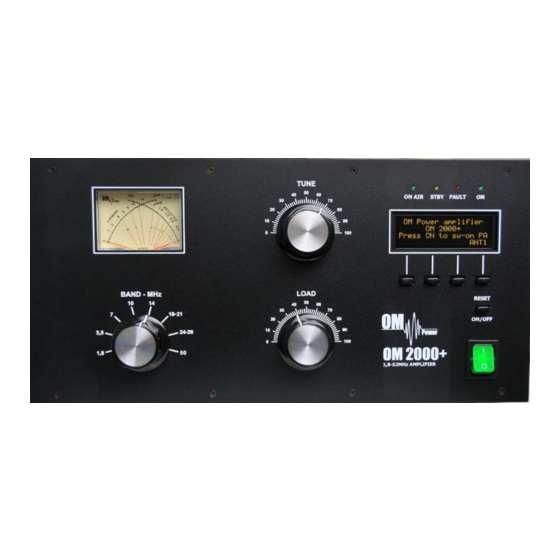
OPERATION% WARNING!) Before)switching)PA)on,)make)sure)that)amplifier)is)grounded,)antenna)or)dummy)load)is)connected,) and)line)cord)is)putted)to)the)outlet.)Be)sure)you)selected)AC)input)by)7.1.) CAUTION) Before)switching)PA)on,)check)all)connections)between)PA)and)TCVR.) CAUTION) Do) not) turn) PA) on) for) at) least) 2) hours) after) unpacking) it) and) locating) in) its) operating) location.) Especially) when) amplifier) is) moved) from) a) cold) place) to) a) warm) one) because) not) visible) condensation)may)develop,)and)this)could)result)in)damage)to)the)high)voltage)circuits)of)the)PA.)) CAUTION) Never)try)to)change)antenna)output)during)a)transmission)to)avoid)warranty)loss.) - Page 13 BAND))))))))]) ))Band!selector!switch) TUNE)))))))))])) ))Anode!capacitor!for!tuning!!! !(higher!frequencies!to!"0";!!lower!frequencies!to!„100“).! LOAD)))))))))))))]!!!!!!Output!capacitor!tunes!antenna!load!resistance!to!the!amplifier.!! !!!!!!!!!!!!!!!!!!!!!!!!!!!!Capacity!is!low!at!„100“!and!high!at!"0"!on!the!scale.! WATMETER)]))))))Analog!double!system!meter!for!forward!and!reflected!power!measuring) ))))ON)/)OFF))))]!!!Long!press!(abt.!1!sec.)!to!switch!PA!ON/OFF! ))))RESET)))))))))]!!!Short!press!to!reset!faults!or!warnings) ))))0)/)I))))) Power!ON)small!12V!APU!for!logic!and!protection!circuits!! !!!!!!!!!!!!!!!!!!!!!You!can!switch!Antenna!ports!even!if!PA!is!switched!OFF.! ))))))))))))))S1))))))))))))S2)))))))))))))S3)))))))))))))S4) Exhibit!6!!!!!!!!!!!!!!!!!!!!!!!!!!!!!!!!!!!!!!!!!!!!!!!!!!!!!!!Page!13!!from!35!
-
Page 14: Preparation!For!Operation
ON)AIR))))])!!Transmitting!mode!LED!! STBY!!!!!!!!a!!!Standby!mode!LED! FAULT)!!!!a!!!Failure!!LED!!!!!!!! ON!!!!!!!!!!!a!!!PA!is!„ON“!LED! S1)))))))))))))]))OPER)/)STBY)!!a!!!Press!to!switch!between!Standby!and!Operation!mode! !!!!!!!!!!!!!!!!!!!!!ESC)!!!!!!!!!!!!!!!!!!!a!!!Return!to!the!previous!level! S2)))))))))))))]))MENU!!!!!!!!!!!!!!!a!!!Enter!the!Menu! !!!!!!!!!!!!!!!!!!!!DOWN!!!!!!!!!!!!!!!a!!!Scroll!down! !!!!!!!!!!!!!!!!!!!!!!!!! S3)))))))))))))]))DSP!!!!!!!!!!!!!!!!!!!!a!!!Change!display!(DSP1,!DSP2,!DSP3)! )))))))))))))))))))))UP!!!!!!!!!!!!!!!!!!!!!!a!!!Scroll!up! S4)))))))))))))]))ANT!!!!!!!!!!!!!!!!!!!a!!!!Change!Antenna!output!!(ANT1,!ANT2,!ANT3)! )))))))))))))))))))))ENT!!!!!!!!!!!!!!!!!!!a!!!!Confirm!the!selection! More!functions!of!S1aS4!buttons!will!be!described!in!next!parts!of!this!manual.! 5.2. Preparation'for'operation' The!first!necessary!thing!after!connecting!AC!to!the!power!amplifier!is!switching!main!(green)!switch!to! „!I!“.!!Welcome!message!and!then!starting!information!appears!on!the!display:! After! switching! main! switch! ON! welcome! message!appears!shortly.! Starting! message! shows! which! antenna! is! connected.! To! switch! PA! ON! press! ONaOFF! button!for!abt.!1!second.! Warming! time! takes! abt.! 210! seconds.! It! is! possible! to! enter! MENU! during! this! time,! but! with! limited! possibilities! (display! settings! can! be!changed,!for!example).! -
Page 15: Display!Menu
If!you!change!DSP!during!warming!time,!you!lost!count!down!information.!Press!BACK)(S1))to!restore) starting!message.!! When!warming!time!expires,!PA!switches!itself! automatically!to!the!STBY!mode.! You!have!two)possibilities!now!a!switch!PA!to! OPER!mode!and!start!operation,!OR!to!go!thru! MENU! and! submenus! to! set! display! parameters,!some!hardware!parameters!or!to! enter!the!service!menu.!! In!the!STBY!mode!Antenna!output!can!be!changed!(ANT1,)ANT2,)ANT3)!by!pressing!S4.!! Display! information! can! be! changed,! too.! Press!S3!to!do!it.! There!are!3!different!display!settings!possible! in! the! OM2000+.! To! set! display! parameters,! go! to! the! next! part! of! this! manual! for! more! details.! 5.2.1. - Page 16 After! pressing! MENU! (S2)! S1–S4! buttons! changed! their! functions.! To! edit! display! parameters,!press!DISP!button.! Press!DIS1!to!edit!first!display.! Now!you!can!define!parameters!for!first!three! rows.!!Start!with!first!line,!press!1Row)button.) Go!UP!or!DOWN!to!select!desired!parameter.! Press!ENT!to!confirm!selection.! There!are!4!possible!settings!for!the!first!line!(one!baragraph!or!three!pairs!of!different!parameters):! Forward!bar]graph! • Forward!Power!_!Reflected!Power! • Forward!Power!_!SWR!! • Plate!voltage!!Up!!_!Plate!current!Ip! • Second! and! third! line! are! divided! to! the! left! and! the! right! side,! editable! independently.! To! each! of! these!positions!one!of!the!15!different!parameters!should!be!set.!! If!you!finish!first!line!settings,!press!ESC!to!go! back!to!the!row!selection.!
-
Page 17: Settings!Menu
S2!and!S3!now!changed!their!functions.!! To!edit!left!side!of!the!second!line,!press!LEFT' button.! Go!UP!or!DOWN!to!select!desired!parameter.! Press!ENT!to!confirm!selection.! If!you!finish!left!side!settings,!press!ESC!to!go! back!to!the!side!selection.! To! start! edit! right! side,! press! RIGHT) button….etc.! Second!and!!third!line!programmable!parameters!are:! Forward!Power! • Reflected!Power! • Input!Power! • SWR! • TUNE! • Temperature! • Frequency! • Plate!voltage!–!Up! • Plate!current!–!Ip! • Screen!voltage!–!Us! • Screen!current!–!Is! • Screen!current!–!graph! • Grid!voltage!–!Ug! •... - Page 18 Electronic)Bias)Settings!(EBS)!is!one!of!significant!feature!of!the!power!amplifier.!It!allows!to!set!low! plate!current!after!pressing!the!PTT!regardless!of!whether!you!have!CW!or!SSB!mode,!!until!RF!signal!is! no! present! at! the! input.! ! At! the! moment! when! RF! signal! comes! to! the! input! of! PA,! bias! will! automatically!change!to!its!working!value.! EBS)level!means!level!of!the!Input!power,!where!EBS!starts!working.!Default!EBS!value!is!0.2!W.!We! recommend!using!EBS!ON.!Significant!accompaniment!of!used!EBS!is!temperature!reducing.!! To! enter! Settings! menu,! go! to! MENU! first,! then!press!SET!button.! Use! UP! or! DOWN! button! to! select! EBS! ON/OFF.! Press! ENT! to! enter! EBS! status! settings.! Press! ON! or! OFF! to! set! status! of! EBS.! Press!
-
Page 19: Service!Menu
If! you! wish! to) restore) factory! default! parameters,!use!UP!or!DOWN!button!to!select! Restore!default!parameters.!Then!press!ENT.! Press!YES!for!1!second!to!confirm!restoring.! Use! UP! or! DOWN! button! to! select! LCD! contrast.!Press!ENT.! Use!UP!or!DOWN!button!to!set!contrast!value.! Press!ENT!to!confirm!settings.! 5.2.3. Service'menu' In! the! Service! menu! it! is! possible! to! verify! software) version.! This! menu! allows! user! to! check! total! operating)hours!and!listing!in!the!memory,!where!reported!faults)and)warning)messages!are!stored.! You!can!display!particularly!warning!messages!and!particularly!error!messages.!See!chapter!6!for!more! information!regarding!to!warnings!and!faults!occurrence.!There!you!can!find!a!coding!table!together! - Page 20 Use! Service! menu! after! replacing! the! tube.! This!is!step!No.!1.! To!enter!Service!menu,!go!to!the!MENU!first,! then!press!SERV!button.! Use! UP! or! DOWN! button! to! check! software! version.!! Use! UP! or! DOWN! button! to! select! Time! ON! parameter.! Press! ENT! to! see! total! operating! hours!of!the!PA.! Press!ESC!to!go!back!to!the!Service!menu.! Use! UP! or! DOWN! button! to! select! Faults.! Press!ENT!to!see!fault!numbers!or!letters!(see! the!table!in!chapter!6).! Press!ESC!to!go!back!to!the!Service!menu.!
- Page 21 Use! UP! or! DOWN! button! to! select! Warnings.! Press! ENT! to! see! warning! numbers! or! letters! (see!the!table!in!chapter!6).! Press!ESC!to!go!back!to!the!Service!menu.! Use!this!procedure!after!replacing!the!tube.! This!is!step!No.!2.! Scroll!UP!or!DOWN!to!select! EBS1!settings.!Press!ENT!to!start!automatic! adjustment!of!EBS1!(20!mA).! Automatically! increasing! of! the! grid! voltage! (decrease! of! the! negative! value)! causes! a! gradual! increase! in! the! plate! current.! In! the! moment,! when! Ip! reaches! 20mA,! adjustment! stops.!Press!ESC!after!stopping.! Use! this! procedure! after! replacing! the! tube.!
-
Page 22: Operation!Mode
Use!UP!or!DOWN!to!select!Calibration!Ip!&!Is.!! Press!ENT!to!do!it.! Ip!and!Is!calibration!runs!in!the!background.!! Result!only!is!visible!on!the!display.!! Press!ESC!to!go!one!level!back.! 5.3. Operation'mode' CAUTION) In STBY the amplifier is in bypass-mode and your transceiver is directly connected to the antenna. Maximum allowed power in bypass mode is 100 Watts! Passing RF power is measured with analog wattmeter only. It is not displayed if PA is either in standby mode or turned OFF. - Page 23 Changing! of! DSP! allows! user! to! watch! couple! of! basic! parameters! of! the! PA! in! operation! mode! without! input! RF! signal.! Notice:! These! are! three! default! display! settings! (software! version!6.1.)! Check all connections again. Set BAND selector, TUNE and LOAD capacitors according to TCVR parameters and delivered tuning table (see next part for more details).
-
Page 24: Tuning!Of!The!Power!Amplifier
5.4. Tuning'of'the'Power'Amplifier' The OM2000+ power amplifier is operated in class AB. Thus it’s possible to obtain a maximum output power at excellent linearity. For this purpose the amplifier has to be tuned carefully CAUTION The)operation)of)a)mistuned)PA)will)cause)malfunctions,)the)increase)of)grid)current)and)problems) with)TVI/BCI.)) CAUTION If the input power is higher than 10W and the power amplifier is NOT correctly tuned, the safety devices will switch it to STBY. - Page 25 Press!OPER!to!enter!operation!mode.!Apply!low)input)power!and!press!PTT.!Be!sure!you!selected!right! BAND,!TUNE!and!LOAD!knob!positions.!!If!you!made!some!mistake,!fault!message!appears:! Safety! circuit! stopped! transmitting,! fault! LED! is!ON!(Fault!code!4!is!saving!to!the!memory).!! Release! PTT,! set! proper! positions! of! BAND,! TUNE! and! LOAD! according! to! the! table! and! press)PTT!again.! Another!mistake!can!occur,!if!you!have!antenna!connected!to!the!wrong!output.!In!such!a!case!„SWR) is)too)high“!error!message!appears.!Change!antenna!output!using!S4!button.! This! is! not! an! optimal! result,! TUNE! indicator! must! go! between! both! arrows.! Use! TUNE! knob! to) get) maximum) output) power) and! LOAD!knob!to!get)indicator)between)arrows.!! Another! example! of! not! optimal! result,! TUNE!
- Page 26 Two! of! important! information! is! visible! –! screen) current) increased,! but! still! is! within! the! allowed! limits.! ! Turn! LOAD! knob! slightly! in! arrows! direction! to) get) TUNE) indicator) between)arrows.) Display!indicates!correct)tuning!of!the!Power! amplifier.! ))))))))))))))))))))))))))))))))))))))))))))))))))))))))))))))))))))))))))))))))Remember! Always!use!TUNE!knob!to!get!maximum!output!power.!Use!LOAD!knob!to!get!TUNE!indicator!on!the! display!to!the!middle!position!between!both!arrows.!Simultaneously!check!if!Is)graph!indicator!stays! within!the!boundaries.!Repeat!both!steps!more!times.) Proper! operation! mode! of! FUa728F! requires! the! plate! voltage! to! be! close! to! 3! kV.! ! If! anode! voltage! without!RF!power!is!much!lower,!watch!the!heating!voltage,!too.!Normally,!heating!voltage!must!be!in! boundaries!from!8.5!to!9!V!without!RF!signal!(DSP3).!!Heating)voltage)level)is)a)reliable)indicator)of) correct)AC)selector)adjustment.!If!you!see!heating!voltage!lower!than!8.5V!without!RF!signal,!change!
- Page 27 To!start)the)second)method!of!fine!tuning,!press!S2)(TUNE)!button!in!OPER!mode.! PA! is! in! the! operation! mode.! After! TUNE! button! (S2)! was! pressed,! it! changes! its! function.!!Now!STOP!is!blinking.! Do!not!press!STOP!button!yet!! Apply!input!power!according!tune!table!(or!lower)!for!selected!band!and!press!PTT.!Use!TUNE)knob!to! get!maximum!output!power.!Use!LOAD)knob!to!get!Is!!graph!indicator!within!the!boundaries.! Display!shows!properly!tuned!PA.! TUNE!indicator!is!in!the!middle,!Screen!current! is!higher,!but!still!inside!the!limits.! After!proper!fine!tuning!release!PTT)and!press!STOP!button.!PA!is!now!prepared!for!operation.! View! on! the! properly! tuned! PA.! Analog! wattmeter! shows! forwarded! and! reflected! power.! After! this! procedure! the! amplifier! is! tuned! correctly! and! ready! to! give! 1500! W! output! power! in! all! operation!modes.!At!optimal!tuning!and!full!output!power!a!positive!max.!50mA!current!goes!through! the!second!grid.!! CAUTION)
-
Page 28: Maintenance
MAINTENANCE% 6.1.'''' ''Indication'of'Fault'Conditions' If!a!fault!condition!appears!during!the!operation!of!the!amplifier,!the!safety!circuits!of!OM2000+!will! react.! There! are! several! warning! or! fault! messages! possible! to! appear! on! the! display,! when! some! the! protection! will! be! activated.! The! OM2000+! power! amplifier! can! report! one! of! the! following! messages:! Power!Out!is!too!high! Refl.!power!too!high! Power!In!is!too!high! Low!output!power!(tune)! Plate!current!too!high! Grid!current!is!high! Screen!current!error! - Page 29 them! one! position! back.! It! means! that! every! time! last! 30! messages! are! visible! on! the! display.! Next! table!shows!limited!values!for!the!safety!circuits!activation.! Fault!code! Parameter! Warning!level! Fault!level! Power!Output!is!too!high! 2200W! 2300W! 1700W!(50MHz)! 1800!(50MHz)! Reflected!power!is!too!high! 250W! 300W! Power!Input!is!too!high! 80W! 100W! Low!output!power!(tune)! >!3dB!below*! Plate!current!!is!too!high! 1.8A! 2.0A! Grid!current!is!too!high! 10mA! 20mA! Screen!current!is!too!high!
- Page 30 An!example!shows!situation!when!Input! power!is!too!high.!By!pressing!PTT!safety! circuit!will!react!quickly,!error!message! appears!and!FAULT!LED!starts!blinking.!In!this! case!screen!current!exceeds!limited!value! (60mA).!! After! abt.! 1! sec.! PA! returns! to! TX! mode.! Reduce!Input!power!to!avoid!fault!repeating.! This!is!the!situation,!when!problem!with!high! Input!power!persists.!Safety!circuits!reacted!3! times,! and! then! switched! PA! to! STBY! mode.! Permanent!fault!appears.! To! return! PA! to! the! normal! operation,! decrease! Input! power! first,! then! reset! fault! status!and!go!back!to!the!OPER!mode.! If! resistor! R1! or! fuse! F3! is! damaged,! safety! circuit! stops! starting! of! the! PA! and! fault!
-
Page 31: Fuse!Replacement
In!the!case!of!some!hardware!failure!or!if!your!power!amplifier!is!not!working!properly,!please!contact! the!manufacturer!or!your!dealer.! WARNING!) Never)try)to)change)or)move)any)part)inside)the)amplifier)except)of)tube)or)fuses.))Substitution)of) parts)may)void)intrinsic)safety!)) Manufacturer’s)contacts:)))))))))))))OM)POWER,))s.r.o.)) ))))))))))))))))))))) )))))))))))))))))930)30)Báč)126) )))))))))))))))))))))))))))))))))))))))))))))))))))))))))))SLOVAKIA)) ))))))))))))) Email:)om]power@om]power.com) 6.2. Fuse'Replacement' The!user!is!allowed!to!change!mains!fuses!(6.3!x!32mm),!accessible!from!the!rear!panel,!only.!In!the! case! of! fuse! (fuses)! interruption! inside! the! power! amplifier,! exchange) can) be) carried) out) only) by) professionally)qualified)person!!!Internal!fuses!are!located!mainly!on!the!SWITCHaon!board!(next!to! the!HV!transformer).!! One! special! fuse! is! used! in! the! model! OM2000+.! In! the! case! of! an! accidental! discharges! in! the! tube! this! fuse! saves! HV! supply!circuits.! -
Page 32: Appendix
APPENDIX% 7.1.' Primary'AC'voltage'selection' Primary!section!of!the!HV!transformer!is!switchable!for!three!values!of!AC!voltage!(220,!230,!!240V).! Factory!settings!is!230VAC.!Before!first!starting!of!the!PA!we!recommend!to!check!the!correct!value! according!to!the!AC!voltage!in!your!network.!Change!the!settings,!if!necessary.! Side)view)on)the)opened)OM2000+) HV)Transformer) AC)Selector) Exhibit!6!!!!!!!!!!!!!!!!!!!!!!!!!!!!!!!!!!!!!!!!!!!!!!!!!!!!!!!Page!32!!from!35! -
Page 33: Removing!The!Hv!Transformer
Remove!the!upper!lid!first.!On!the!right!side!of!the!PA,!next!to!the!HV!transformer!there!are!two!PCBs! mounted.!On!the!left!upper!side!of!the!front!(SwitchaON)!board!connector!J6!is!located.! Use! flat! screwdriver! or! finger! and! press! carefully! ! the! white! ! stick! to! release! contact! and! move! upper! end! of! the! white! jumper! to! the!proper!position,!if!necessary Jumper must be connected between bottom contact and one of remaining contacts. AC voltage is marked next to every contact. - Page 34 Weight of the PA was distributed (transformer kg, too). has 12 kg, rest of the PA has cca 12 When refitting the transformer, watch to the correct location of individual sections and wires. NOTE Manufacturer reserves the right to make future changes in the way of connecting the transformer to the board.
- Page 35 7.3. Block'Diagram'of'OM2000+'Power'Amplifier' Exhibit!6!!!!!!!!!!!!!!!!!!!!!!!!!!!!!!!!!!!!!!!!!!!!!!!!!!!!!!!Page!35!!from!35!
Need help?
Do you have a question about the OM2000+ and is the answer not in the manual?
Questions and answers