
Related Manuals for OM POWER OM2200HF


Summary of Contents for OM POWER OM2200HF
- Page 1 OM2200HF MADE IN SLOVAKIA SHORTWAVE POWER AMPLIFIER WWW.OM-POWER.COM OM POWER, s.r.o. 93030 Báč 126 SLOVAKIA ontact : +421 905 321 410 e-mail : om-power@om-power.com...
-
Page 2: Table Of Contents
TABLE OF CONTENTS GENERAL INFORMATION Introduction ……………………………………………………………….. 1.1. Specification ……………………………………………………………..1.2. 1.2.1. Parameters …………………………………………………………………. 1.2.2. Protection Circuits ………………………………………………………… 1.2.3. Indicators ………………………………………………………………….. ……………………………………………… SAFETY INSTRUCTIONS ………………………………………………. GENERAL DESCRIPTION HF part ……………………………………………………………………. 3.1. Power Supply …………………………………………………………….. 3.2. Safety Devices ……………………………………………………………. 3.3. ………………………………………………………… INSTALLATION Grounding …………………………………………………………………... - Page 3 ……………………………………………………………... APPENDIX Block Diagram of OM2200 HF Power Amplifier ……………...………... 7.1.
-
Page 4: General Information
GENERAL INFORMATION 1.1. Introduction The OM Power model OM2200 HF is a manual tuning, full legal limit amplifier, designed for heavy duty use on all short wave amateur bands from 1.8 to 29.7 MHz (including WARC bands) and all modes. It is equipped with one FU728F ceramic tetrode. This type of tube can generate output power up to 2700W. -
Page 5: Indicators
1.2.3. Indicators There are couples of LED and bar graph indicators visible on the front panel to inform you about value of some parameters or operation status: Bar graph indicators Power output - 50 LED Reflected power – 20 LED Current at screen Ig2 –... -
Page 6: General Description
Before opening the upper lid of the amplifier make sure that power supply has been disconnected AT LEAST 5 minutes, allowing the electrolytic capacitors to discharge fully. Disconnect power cord from the outlet! Make sure that all screws holding the case together are properly in place and tightened before carrying the amplifier with the handles! The amplifier must be installed in such a way that free flow of hot air from the tube is allowed. -
Page 7: Power Supply
Top view on the opened OM2200 HF FU728F PWR meter Blower Switch-on board Tetrode Output Pi-L Circuit Tuning capacitor Subpanel Power supply board 3.2. Power Supply The power supply consists of 3 kVA toroidal transformer and rectifier block. A soft start is provided using relays and resistors. -
Page 8: Safety Devices
The -120V for the control grid is regulated with zener diodes 3.3. Safety Devices Control and monitoring circuits ensure control and safety during malfunctions of the PA. These are on the Control board, which is located on the chassis subpanel. INSTALLATION NOTE Read this chapter carefully prior you will start installation. -
Page 9: Control Cable
Rear view of the amplifier OM2200 HF AC SOCKET FUSES OUTPUT AUX. FAN CONTROL INPUT 4.3. Control Cable Control cable maintains TX / RX switching of the PA (TX GND). The cable is shielded. On the side of the power amplifier a CINCH-socket is used. On the side of your transceiver you have to use a socket suitable for this transceiver. -
Page 10: Mains Supply
4.4. Mains Supply Be sure you got PA with properly terminated mains cables, corresponding with your power system’s outlet. If not, contact your dealer. In such a case you should make the necessary changes using a licensed electrician. Be sure that your power system is correctly wired and properly rated! To use adequately sized and connected grounding system is also very important. -
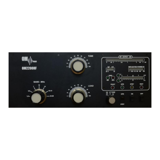
Page 11: Operation Elements
Never try to change antenna output during a transmission to avoid warranty loss. NOTE When you decide to have a short operating break, place the amplifier in the standby mode rather than switch it off. 5.1. Operation Elements There is couple of operational elements accessible or visible on the front panel. BAND- Band selector switch TUNE -... -
Page 12: Tuning Of Power Amplifier
Bar graph – shows output power . RF OUTPUT Bar graph – shows reflected power from the antenna. REFLECTED POWER Maximum level is 350W otherwise amplifier switches to STANDBY mode. Bar graph – measures the current of the second grid from -20mA to +80mA. - Page 13 1. Set the multimeter switch to the HV position 2. Set the OPR/STBY switch to the STBY position 3. Press the ON button The amplifier is prepared for operation with the following automatic steps: The toroidal transformer is switched on. ...
- Page 14 Tuning Table shows proper tuning values for 50 Ohm termination. Band Tune Load 8. Set TUNE knob in such a way, that the TUNE-LED lights up maximum left. 9. Set LOAD in such a way, that the TUNE LED on the TUNE scale lights up under the “V”...
-
Page 15: Maintenance
MAINTENANCE 6.1. Indication of fault conditions OM2200 HF has the following indication LED on the front panel: GRID MIN - Indication of first gird current GRID MAX - Max. First grid current exceeded - Measuring of anode voltage by bar graph - Measuring of anode currency by bar graph FAULT - Fault... -
Page 16: Fuse Replacement
Manufacturer’s contacts: OM POWER, s.r.o. 930 30 Báč 126 SLOVAKIA Email: om-power@om-power.com 6.2. Fuse Replacemeent The user is allowed to change mains fuses (6,3 x 32mm, 20A), accesible from the rear panel, only. In the case of interrupted fuse (fuses) inside the power amplifier, contact your dealer, please. - Page 17 APPENDIX 7.1. Block Diagram of OM2200 HF Power Amplifier...
Need help?
Do you have a question about the OM2200HF and is the answer not in the manual?
Questions and answers