Table of Contents
Advertisement
Quick Links
Download this manual
See also:
Instruction Manual
Advertisement
Table of Contents

Related Manuals for OM POWER OM2500 HF


Summary of Contents for OM POWER OM2500 HF
-
Page 1: Power Amplifier
Instruction Manual OM2500 HF SHORTWAVE POWER AMPLIFIER WITH GU84B... - Page 2 General description of the short wave power amplifier The linear power amplifier is designed for all short wave bands 1.8 to 29 MHz ( including WARC - bands ) and all modes. A Russian GU84b tetrode is used to generate power output up to 2700W That’s PEP of more than 4 kW ! Characteristics: Frequency:...
- Page 3 General Description of OM2500 HF POWER AMPLIFIER Top view of the opened amplifier HF PART In this amplifier a tetrode GU 84b is used in a grounded-cathode circuit ( input into control grid ). This amplifier achieves excellent linearity by the voltage stabilization of the control grid bias and the screen voltage.
-
Page 4: Coaxial Cable
SAFETY DEVICES Safety devices and the corresponding indicators ensure proper operations and prevent the malfunctioning of the power amplifier. They are placed on a separate printed board behind the front panel. Putting the power amplifier into operation Coaxial cable The output of the transceiver is to be connected with the input of the amplifier via RG58 or a similar cable. - Page 5 If you use older transceivers or transmitters without time delay we recommend to connect the PA in such a way that the transmit / receive switch is connected with the KEY IN socket of the amplifier. The KEY OUT socket is to be connected with the PTT socket at the transceiver.
-
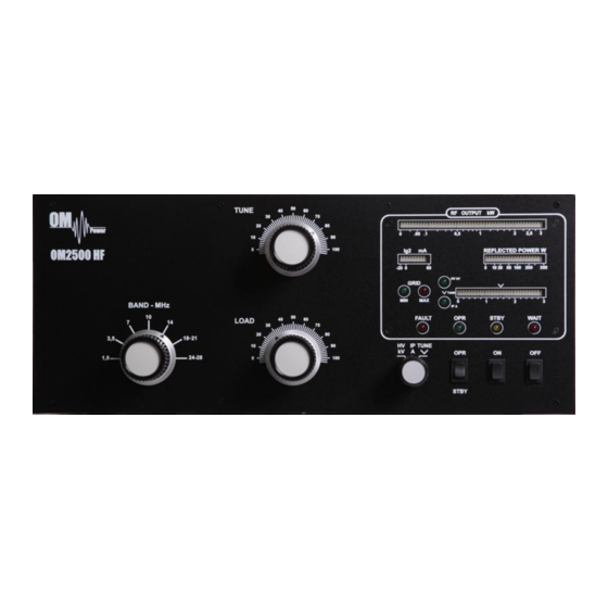
Page 6: Operating Elements
Operating elements (see photo) BAND - band selector switch TUNE - Anode capacitor for tuning, tuning of higher frequencies to "0", lower frequencies to „100“. LOAD Output capacitor tunes antenna load resistance to amplifier. Capacity is low at „0“ and high at "100" on the scale. OFF - You switch off the amplifier by pressing this button. - Page 7 Tuning instruction : Please note : Before starting tuning you have to check if the right antenna or a 50 Ohms load resistance is connected at the antenna output ! Switching on the amplifier: - put the switch at the multimeter to HV position - put the OPR/STBY switch to STBY position - press the „ON“...
- Page 8 Please note! If the input power is higher than 15 W and the power amplifier is not correctly tuned, the safety devices will switch to STBY for about 4 seconds! After switching off the PTT, the amplifier will automatically switch back to OPR mode after approximately 4 seconds.
Need help?
Do you have a question about the OM2500 HF and is the answer not in the manual?
Questions and answers