
Related Manuals for OM POWER OM2500 A-F


Summary of Contents for OM POWER OM2500 A-F
- Page 1 Instruction Manual OM2500 A-F SHORTWAVE POWER AMPLIFIER OM POWER, s. r. o. 930 30 Báč 126 SLOVAKIA E-mail: om-power@om-power.com...
-
Page 2: Table Of Contents
TABLE OF CONTENTS GENERAL INFORMATION Introduction ……………………………………………………………….. 1.1. Specification ……………………………………………………………..1.2. 1.2.1. Parameters …………………………………………………………………. 1.2.2. Protection Circuits ………………………………………………………… 1.2.3. Indicators ………………………………………………………………….. SAFETY INSTRUCTIONS ……………………………………………… GENERAL DESCRIPTION ………………………………………………. HF part ……………………………………………………………………. 3.1. Power Supply …………………………………………………………….. 3.2. Safety Devices ……………………………………………………………. 3.3. INSTALLATION ………………………………………………………… Grounding …………………………………………………………………... - Page 3 5.2.7. MUTE Option …………………………………………………………….. 18 5.2.8. LCD Settings Menu ………………………………………………………. 19 5.2.9. Operation in MANUAL Mode …………………………………………… 19 Tuning of Power Amplifier …………………………………………….. 5.3. 5.3.1. AUTO or MANUAL ……………………………………………………. 5.3.2. Manual Tuning Instructions ……………………………………………... 20 5.3.3. Tuning Adjustment ……………………………………………………….. 22 MAINTENANCE ……………………………………………………….
-
Page 4: General Information
GENERAL INFORMATION 1.1. Introduction The OM Power model OM2500A-F is a fully automatic, full legal limit amplifier, designed for heavy duty use on all short wave amateur bands from 1.8 to 29.7 MHz (including WARC bands) and all modes with no time limit. It is equipped with one FU-728F ceramic tetrode. -
Page 5: Indicators
Screen current too high Grid current too high Mistuning of PA Hot switching protection Soft start for protecting your fuses “switch-on blocking “ at opened amplifier 1.2.3. Indicators There are couples of LED and bar graph indicators visible on the front panel to inform you about value of some parameters or operation status: Bar graph indicators Power output - 50 LED... -
Page 6: Safety Instructions
SAFETY INSTRUCTIONS WARNING! DANGEROUS HIGH VOLTAGE! The power amplifier is using high voltage up to close 3200V DC, which is very dangerous for human life! Read next safety instructions carefully first, before you will start to install and operate power amplifier! NEVER VIOLATE NEXT RULES! WARNING! NEVER ALLOW CHILDREN to play around PA or to touch power... -
Page 7: General Description
GENERAL DESCRIPTION 3.1. HF part In this amplifier a tetrode FU-728F is used in a grounded-cathode circuit (input into control grid). This amplifier achieves excellent linearity by the voltage stabilization of the control grid bias and the screen voltage. The power input is given to the control grid, using a broadband input circuit with an input impedance of 50 Ohms. -
Page 8: Power Supply
3.2. Power Supply Power supply of the amplifier is comprised of two of 2,0 kVA toroidal transformers. A soft start is provided using relays and resistors. The high anode voltage is made by combining 8 x 400 V (total 3200V) @ 1.5A. Each has its own rectifier and filter. -
Page 9: Coaxial Cable
4.2. Coaxial Cable The output of the transceiver is to be connected to the input of the amplifier via RG58 or similar cable. For the connection between the power amplifier and the antenna, RG213 or similar coaxial cable suited for high power is recommended. Both the INPUT and OUTPUT SO-239 sockets with Teflon insulation is used. - Page 10 KEY IN RCA Phono - Input signal PTT switching voltage / current 5V /2 mA) KEY OUT RCA Phono - Output signal PTT (maximum switching of 30V / 50mA) CI-V Mono 3.5mm Jack for connection of ICOM TCVRs or devices that provide compatible CI-V protocol.
-
Page 11: Main Supply
PIN OUT: 1. ALC Out 2. NC 3. INHIBIT Control voltage 4. TX INHIBIT for Yaesu and Elecraft – this supersedes ALC output 5. NC 6. KEY OUT 7. NC 8. KEY IN 9. – 15. GND ANT & BPF SW DB-25 is used for switching of external HP BPF or external Antenna Switch. -
Page 12: Cooling
CAUTION Be sure you got PA with properly terminated line cable, corresponding with your power system’s outlet. If not, contact your dealer. In such a case you should make the necessary changes using a licensed electrician. WARNING! Be sure that your power system is correctly wired and properly rated! To use adequately sized and connected grounding system is also very important. -
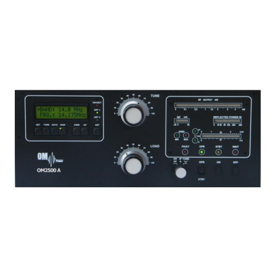
Page 13: Operation Elements
5.1. Operation Elements There are couple of operational elements accessible or visible on the front panel. TUNE - Anode capacitor for tuning, tuning of higher frequencies to "0", lower frequencies to „100“. LOAD - Output capacitor tunes antenna load resistance to amplifier. Capacity is low at „100“... -
Page 14: Configuration Of Power Amplifier
INHIBIT Indicates interruption of transmission during the tuning process of the PA. If indicated by RED LED then PA is in STBY mode. If during a retune operations within same BAND then the PA will retune according to the frequency of the transceiver. When changing the BAND – INHIBIT will stay lit until the KEY IN is released and the tuning process will start. -
Page 15: Tcvr Support Settings
Example of Automatic mode with ICOM TCVR. Type of supported TCVR and working frequency are visible on the display. AUTO LED is ON. 5.2.1. TCVR Support Settings Supported transceivers: ICOM, ELECRAFT, KENWOOD, TEN-TEC , ORION, YAESU Press SET button and scroll using UP / DWN to CHOOSE TCVR Confirm CHOOSE TCVR by pressing SET again and scroll UP / DWN to your transceiver type. -
Page 16: Connection With No Supported Tcvrs
When using Yaesu TCVR you need to configure the STOP BIT parameter correctly and confirm selection with SET. The communication settings menu can be left by pressing the AUTO button. The amplifier will enter AUTO mode only if all settings are correct and connection has been established with your transceiver. -
Page 17: Antenna Switching Menu
5.2.4. Antenna Switching Menu If you have 3 party external antenna switch connected to your amplifier ( i.e. MicroHAM TEN SWITCH), you need to configure the assignment of each port to a specific band /or antenna. By pressing SET and scrolling to ANTENNA SETTINGS and confirming by SET you get current band and its antenna selection. -
Page 18: Loading Factory Default Settings
5.2.6. Loading factory default settings In the rare case of needing to restore factory default settings press SET and scroll using UP / DWN to LOAD DEF VALUES and confirm by SET. Then select if you want to erase all settings (pressing TUNE) or just one setting value (SET button). -
Page 19: Lcd Settings Menu
5.2.8. LCD Settings Menu By pressing SET and scrolling UP / DWN and selecting LCD CONTRAST (Confirming by SET) and pressing Up or DWN you can vary the Contrast of the LCD display. Press SET for confirm the setting. 5.2.9. Operation in MANUAL mode To enter Manual mode of the PA please press MAN. -
Page 20: Tuning Of Power Amplifier
5.3. Tuning of Power Amplifier The OM2500A-F amplifier is operated in class AB. Thus it’s possible to obtain a maximum output power at excellent linearity. For this purpose the amplifier has to be tuned carefully. WARNING! Before starting tuning you have to check if the right antenna or a 50 Ohms load resistance is connected at the antenna output! CAUTION The operation of a mistuned PA will cause malfunctions, the increase of grid current... - Page 21 1. Set the multimeter switch to the HV position 2. Set the OPR/STBY switch to the STBY position 3. Press the ON button The amplifier is prepared for operation with the following automatic steps: Toroidal transformers are switched on step by step. ...
-
Page 22: Tuning Adjustment
After this procedure the amplifier is tuned correctly and ready to give 1500W output power in all operation modes. At optimal tuning and full output power a positive max. 50mA current goes through the second grid. On 24 and 28 MHz bands optimal tuning can be achieved when one or two LEDs are lit up to the left from the position “V”. -
Page 23: Maintenance
HV + IP - tuning fault, incorrect tuning of the Pi-L output circuit In case your OM2500A-F amplifier is not working correctly, please contact the manufacturer or your dealer. Manufacturer’s contacts: OM POWER, s.r.o. 930 30 Báč 126 SLOVAKIA Email: om-power@om-power.com... -
Page 24: Fuse Replacement
Dealer in USA: Array Solutions 2611 North Belt Line Road Suite # 109 Sunnyvale, TX 75182 Tel: (214)954-7140 Email: sales@arraysolutions 6.2. Fuse Replacemeent The user is allowed to change mains fuses (6,3 x 32mm), accesible from the rear panel, only. In the case of interrupted fuse (fuses) inside the power amplifier, contact your dealer, please. -
Page 25: Appendix
APPENDIX 7.1. Example of connection for Icom... -
Page 26: Example Of Connection For Elecraft
7.2. Example of connection for ELECRAFT... -
Page 27: Example Of Connection With Yaesu
7.3. Example of connection with Yeasu... -
Page 28: Example Of Connection With Antenna Switch And Bpf
7.4. Example of connection with antenna switch and BPF... -
Page 29: Example Of Connection Usb Micro Keyer
7.5. Example of connection USB micro KEYER II with IC7800 or IC7700... -
Page 30: Example Of Connection Usb Micro Keyer Ii With Another Icom
7.6. Example of connection USB micro KEYER II with another Icom... -
Page 31: Example For Connection Usb Micro Keyer
7.7. Example for connection USB micro KEYER II with Yeasu or ELECRAFT... -
Page 32: Example Of Connection Pa With Microham Mkii, (Mk2R+ Etc ) With Ci-V Output
7.8. Example of connection PA with MicroHAM MKII, (MK2R+ etc ) with CI-V output... -
Page 33: Block Diagram Of Om2500A-F Power Amplifier (Usa Version)
9.1. Block Diagram of OM2500A-F Power Amplifier (USA version)
Need help?
Do you have a question about the OM2500 A-F and is the answer not in the manual?
Questions and answers