
Related Manuals for OM POWER OM2000 HF


Summary of Contents for OM POWER OM2000 HF
- Page 1 Instruction Manual OM2000 HF ”one phase” SHORTWAVE POWER AMPLIFIER OM POWER, s. r. o. 930 30 Báč 126 SLOVAKIA...
-
Page 2: Important Safety Instructions
The amplifier contains high voltage circuits. Never turn the amplifier on without the upper lid in place. The OM2000 HF amplifier is not to be used in a wet or humid environment not to be exposed to rainfall. - Page 3 General description of the OM2000 HF Amplifier The linear amplifier OM2000 HF is designed for all short wave amateur bands from 1.8 till 29 MHz (including WARC – bands ) and all modes . It is equipped with a ceramic tetrode GU84b.
- Page 4 General Description of OM2000 HF POWER AMPLIFIER HF PART In this amplifier a tetrode GU84b is used in a grounded-cathode circuit (input into control grid). This amplifier achieves excellent linearity by the voltage stabilization of the control grid bias and the screen voltage.
-
Page 5: Power Supply
POWER SUPPLY Power supply of the amplifier is effected by one 2.5 kVA toroidal transformer. A soft start is realized with the help of relays and resistors. The high anode voltage consists of 8 times 350 V and 1,5 A. Each of them has its own rectifier and filter. -
Page 6: Main Supply
During transmitting the middle pin is connected to the ground. The relays of the OM2000 HF have to be switched earlier than HF is applied (cold switching). Modern transceivers have a time delay between PTT switching and power output. -
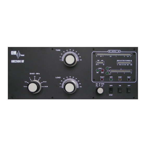
Page 7: Reflected Power
HV/IP/TUNE bargraph – measure the anode voltage, anode currency or tuning of the amplifier TUNING The OM2000 HF amplifier is operated in class AB. Thus it’s possible to obtain a maximum output power at an excellent linearity. For this purpose the amplifier has to be tuned carefully. - Page 8 Tuning instruction: Please note: Before starting tuning you have to check if the right antenna or a 50 Ohms load resistance is connected at the antenna output! Switching on the amplifier: put the switch at the multimeter to HV position ...
- Page 9 4. Choose TUNE position of multimeter. 5. Switch the PA to CW and increase driver power to 10W (OUTPUT power will be abt. 500W) Please note! If the input power is higher than 15 W and the power amplifier is not correctly tuned, the safety devices will switch to STBY.
-
Page 10: Indication Of Fault Conditions
Should a fault condition appear during the tuning or operation of the amplifier the safety circuits of OM2000 HF will react. The amplifier will be turned to STBY mode. After approx. 1 sec the control circuits will switch the amplifier back to OPR. If the fault will repeat 3 times after each other the control circuits will turn the amplifier to STBY.
Need help?
Do you have a question about the OM2000 HF and is the answer not in the manual?
Questions and answers