
Subscribe to Our Youtube Channel
Related Manuals for Lewmar AutoAnchor 550


Summary of Contents for Lewmar AutoAnchor 550
- Page 1 AUTOANCHOR AutoAnchor 550 v1.9 Chaincounter and Windlass Contro Operation Manual...
-
Page 2: Table Of Contents
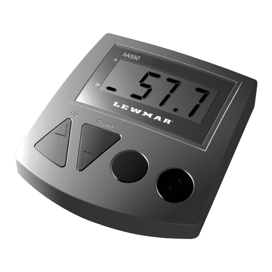
Important Information i-iii Part 1 Features Part 2 Calibration Part 3 Operation Safety Lock Manual Operation Automatic Operation Reset Display to Zero Change Backlighting Level Reset Factory Default Settings Part 4 Troubleshooting & Maintenance Index AutoAnchor 550 Diagram Feet Indicator Display Screen Metres Indicator Note: The Feet/Metres Indicator pulses when the Mode On/Off Down sensor is operating... - Page 3 Windlass & Anchor Installation The windlass must be installed according to the windlass manufacturer’s instructions with the correct size chain. The AA550 will not count correctly if the windlass is not standard (eg it is installed with a different chainwheel or motor). It must also be regularly serviced and lubricated. For smooth operation, the windlass requires a good quality, properly fitted bow roller and a swivel should be connected to the anchor where it joins the chain. Calibration and Testing Before using the AA550 it must be calibrated to the windlass and rode on the boat and tested in a safe environment.
- Page 4 Electromagnetic Compatability (EMC) The AA550 meets and exceeds the CE standard for EMC (EN60945). These standards are intended to provide reasonable protection against interference by other emission generating products on the boat. However, compliance with these standards is no guarantee that inter- ference will not occur in a particular installation. The installation in- structions must be followed to minimise the potential for interference. AA550 Use It is the owner’s sole responsibility to ensure the AA550 is installed, used and maintained in a manner that will not cause accidents, per- sonal injury or property damage. When using the AA550 the operator must use safe boating practices and safe windlass and anchoring opera- tion. Before using the AA550 the operating instructions must be read and understood and the AA550 must be calibrated and tested. The AA550 makes anchoring less stressful but nothing can replace good seamanship and safe boating practices. The user of the AA550 must: • use the windlass strictly according to the windlass manufacturer’s instructions; • personally control and supervise all windlass and anchoring operations;...
-
Page 5: Part 1 Features
ArT 1 - EATUrES The AA550 provides easier windlass control and security in knowing how much anchor rode has been released. AFETY EATUrES • The safety lock reduces the chance of unintentional windlass operation from the console • The safety cutout allows you to press any button on the console unit to stop windlass operation when using the automatic function • The anchor retrieval stopping point (when using the automatic function) stops the windlass motor before the anchor reaches the boat and the AA550 beeps to warn the operator to change to manual operation for final docking of the anchor. • During final docking the AA550 beeps continuously while the operator is pushing the up button IAGNOSTICS Electronic fault diagnostics help to identify problems with: • The power supply • The wiring • The sensor • Windlass rotation EASUrEMENT • Anchor rode measurement is in feet or metres • Settings and measurements are retained if the unit is turned off or the battery fails • The counting operation continues if the windlass is operated by another switching mechanisim on the boat (eg deckswitches) ECHNICAL PECIFICATIONS - AA550 v1.9 Power Supply: 12V or 24V DC Current Consumption: 50mA Temperature Range: 23 F to 140 F ( -5 C to 60 Solenoids: Max 4 Amp draw Maximum Voltage: 30V DC... -
Page 6: Part 2 Calibration
ArT 2 - ALIBrATION The AA550 must be installed and operated in accordance with the instructions supplied. Non compliance with any of these instructions could impair windlass and AA550 operation and will negate the manufacturer’s warranty. Before operation the AA550 must be calibrated to comply with the boat’s windlass and anchor rode and then tested in a safe environment. - Page 7 After selecting feet or metres, enter calibration mode as follows: Turn the AA550 off. Step 1 Step 2 Hold down the MODE button and press and release the ON/OFF button. Release the MODE button. The AA550 will flash between Item 1 and the current setting. (Refer below). Item Setting Item1: Safety Lock Default Setting is ON Record Calibration Entered: ___________________ The safety lock should be left ON at all times. If you choose to disable the safety lock use the UP or DOWN button to change the display setting to OFF. To set the safety lock again press the UP or DOWN button to reset to ON. Press the MODE button to advance to the next item. The display will flash between Item 2 and the cur- rent setting for Item 2. Item Setting Item 2: Anchor retrieval Stopping Point Default Setting 4 ft or 1.5 m Record Calibration Entered: ___________________ This sets the length of rode to be retrieved by manual operation of the unit after the automatic upward control has stopped. For safety...
- Page 8 Item Setting Item 4: This setting is not used for the AA550. It cannot be changed from OFF. Press the MODE button to advance to the next item. The display will flash between Item 5 and the current setting for Item 5. Item Setting Item 5: This setting is not used for the AA550. It cannot be changed from OFF. Press the MODE button. The display will flash between Item 6 and the current setting for Item 6. Item Setting Item 6: Chainwheel Circumference...
- Page 9 Measure the length of chain from the mark on the deck to the Step 6 mark on the chain. (See Fig 6). This measurement is the setting to enter. Step 7 Use the UP or DOWN buttons to enter the setting.The setting is entered in inches (in increments of 0.10) or millimetres. Chainwheel Mark Chain Mark Fig 5 Deck Mark After 1 turn of the chainwheel to feed Fig 6 chain out Distance to measure (inches or mm) Item 6 is the final calibration. Now save the settings: Save To save the settings, hold down the MODE button until Prog is displayed, then release the MODE button. The unit will then return to normal operation. To Abort and re-start Calibration Press and hold the ON/OFF button until Abrt is displayed. Release the ON/OFF button. The AA550 is now off. Hold down the MODE button, and press and release the ON/OFF button. Release the MODE button to restart calibration at Item 1.
-
Page 10: Part 3 Operation
ArT 3 - PErATION ARNING Before using the AA550 the operating instructions must be read and understood, the AA550 must be calibrated to the wind- lass and rode on the boat and it must be tested in a calm, safe environment. -
Page 11: Safety Lock
AA550 PErATE AFETY OCk (C) The AA550 is fitted with a safety lock to help protect against unintentional windlass operation. Before operating the windlass the safety lock must be released. When the safety lock is on, the screen shows C and the UP and DOWN buttons will not operate. To release the Safety Lock: Turn the AA550 on, hold down the MODE button until C clears from the screen, then release the MODE button. Note: The safety lock automatically reactivates 5 minutes after the AA550 was last operated. It can also be reactivated manually at any time. To do this hold down the MODE button until C is displayed on the screen. Release the MODE button and the safety lock is set. The safety lock reactivates automatically when the console unit is turned off. The AA550 can be operated manually or by using the unique automatic function. Always ensure the AA550 display reads 0.0 before releasing the anchor from the docked position. -
Page 12: Automatic Operation
To retrieve the Anchor and rode - Using Manual Operation Turn the AA550 on. Step 1 Step 2 Clear the safety lock (Refer to page 8). Press and hold the UP button to start the windlass and Step 3 retrieve the anchor and rode. Step 4 Release the UP button to stop the windlass operation when the anchor is fully retrieved and docked. Step 5 Ensure the anchor is fully docked and secured before moving the boat Note: During retrieval the AA550 will beep to warn the operator the anchor has passed the preset anchor retrieval stopping point. (Refer Item 2, page 4). Extra care must be taken at this stage of retrieval. UTOMATIC PErATION The AA550 has a unique automatic function. Using this function the... - Page 13 UT0MATIC NCHOrING Enable Automatic Operation: The AA550 is supplied with the length of rode to be released set to OFF. The automatic function cannot be used until a “rode to be released” value is entered. (See Step 3 below). Once a “rode to be released” value has been entered the AA550 remains enabled for automatic operation. The setting is retained by the AA550 even if the battery fails. To disable the automatic operation use the DOWN button to reset the “rode to be released” to OFF. To release the Anchor and rode Step 1 Turn the AA550 on. Clear the safety lock if necessary. (Refer to page 8). Step 2 Press the MODE button once. The value flashing shows Step 3 AUTO and the preset length of rode to be released. If this value is cor- rect go to Step 4 below. To change the rode to be released setting: Press MODE again. The display will flash between SET and the current value. (The default setting is OFF). Use the UP or DOWN buttons to change the setting. Press the MODE button again to return to AUTO and go to Step 4 be- low to release the anchor. Or press the MODE button twice to return to normal operation. If you do not change the SET value, press the...
-
Page 14: Reset Display To Zero
AFETY VErrIDE - Press any button on the AA550 to stop the windlass during automatic release or retrieval. To restart press the MODE button once to enter automatic operation again and resume rode and anchor release or retrieval. IN AN EMErGENCY SHUT OFF THE POWEr TO THE WINDLASS USING THE ISOLATING/BrEAkEr SWITCH. -
Page 15: Change Backlighting Level
Change Backlighting Level (This is best done in low light). Turn the AA550 on. Clear the safety lock if necessary. Press and hold the ON/OFF button down. The AA550 will start to beep. Press and hold the UP or DOWN buttons to adjust the light level. When you reach the desired level release the UP or DOWN buttons before you release the ON/OFF button. Note: If the ON/OFF button is held down for longer than 2 seconds without starting the adjustment this will reset the AA550 display to zero. reset Factory Default Settings This setting should only be used if the AA550 settings have been corrupted. Using this setting will remove all your calibration settings. To apply the factory reset: Turn the AA550 off. Hold down the MODE and UP buttons together. While holding these buttons press and release the ON/OFF button. When the LCD display reads LoAd release the MODE and UP buttons. The unit will turn itself off and the factory default settings will be reset. -
Page 16: Part 4 Troubleshooting & Maintenance
ArT 4 - TrOUBLESHOOTING & MAINTENANCE OWEr UPPLY THE POWEr SUPPLY MUST BE DISCONNECTED BEFOrE MAkING ANY CHANGES TO WIrING Or ELECTrICAL CONNECTIONS. Power to the AA550 and all windlass controls eg. toggle switch, remote switches, deck switches must be supplied from one point or the AutoAnchor will be damaged. - Page 17 ELECTrONIC DIAGNOSTICS Definitions SoL = Solenoid, SEN = Sensor, Lo Pr = Low Power The AA550 is not faulty if these messages are displayed. The diagnostics help identify problems with installation, the battery, the solenoid and the sensor and windlass rotation. Some of the messages appear when you try to operate the AA550 but others only appear briefly when the AA550 is turned on. Always check for the diagnostic messages by switching the AA550 off and then on again. Use the table below to help identify a problem and provide a possible solution. If you cannot resolve the problem, contact your supplier for further information. SEN message: When this message is displayed the AA550 will operate the windlass up and down manually but the Auto function will not work and the count will not be accurate.
- Page 18 4. SEN Use the AA550 up and down manually and Displayed when attempting check for the specific sensor error. Refer to the to use the Auto function. note below. No signal from the sensor to the AA550. 5. SEN 3 Either there is no magnet, the gap between Displayed when the the magnet and sensor is too big or the sen- AA550 is operated manu- sor signal is out of tune because of testing ally. Auto does not work. during installation. AA550 will operate the No sensor pulse. windlass up and down but there will be no count displayed on the LCD. Try resetting the AA550 by running the windlass up and down for 10-15 seconds. If the message still appears check the magnet and the gap and alignment between the magnet and sensor. Check sensor wiring and installation and check for damage to the sensor and magnet. When fixed reset the AA550 as above. To reset manually the anchor must be docked and the AA550 reset to zero twice. To reset to zero - press and hold the ON/OFF button. Release when the display shows 0.0. 6. SoL oL The solenoids could be exceeding the maxi- Displayed when the Up or mum 4 Amps or a solenoid wire is shorted to Down button is pressed. ground. The AA550 is designed to turn the The windlass may operate solenoids off if these events occur. Check the for a short period and then solenoids and the wiring and fix as necessary.
- Page 19 8. AA550 will not turn on or Check battery connections, polarity and turns off. voltage. The voltage to the AA550 can be checked by turning it off and holding the Down button. The voltage is displayed on the LCD. See page 13 for minimum voltages. Check fuses and wiring and for the Lo Pr diagnostic message. Refer note 2 above. Check if the safety lock is on - the LCD 9. AA550 will not will display LoC. Refer note 1 above. operate the windlass. Check voltages at the battery and the AA550. The LCD will display Lo Pr. Refer note 2 above. Check wiring for loose connections to the solenoids. The LCD will display SoL Up or SoL dn if the wires are disconnected. Refer note 7 above. Check that the windlass is not already in operation using the deck switch or remote control. Check the total rode on board (Calibra- tion 3 - Operation Manual Pg 4) is not set to OFF. 10. AA550 will Check the rode to be released is not set to operate the windlass zero. The LCD will display OFF. See note manually but Auto 3 above. Use the AA550 manually and function does not check for diagnostic messages.
- Page 20 12. The windlass This is not a fault. Stopping is accurate to does not stop exactly +1 chainwheel revolution. The chainwheel at the preset point. may run on slightly with momentum. The sensor could be damaged, incorrect 13. AA550 counts cable may be fitted, or the AA550 may have when the windlass is been subject to external interference - RF not turning or counts or electrical. Check that the sensor cable erratically displaying is not damaged and that the cable fitted is a large number eg Beldon 9501 or equivalent, 2 core, tinned, 8888. copper, screened, as specified in the instruc- tions. Check for external interference on the boat eg damaged or loose RF cables or aerials or other instruments that may not be working correctly or have been damaged by electrical interference including lightning. 14. AA550 beeps Anchor rode is running through the when it is turned off windlass. Check if the windlass is being operated using the deck switches or a or locked. remote control. If not, check the windlass and anchor is secured.
- Page 21 ABLE PECIFICATIONS Cable from AA550 Console to the Sensor: Belden 9501 (AWG24) or equivalent, tinned, 2 core, screened. Cable from AA550 Console to batteries and solenoids: All battery and motor cables must be ring type. This specification is based on the total cable length measured from the bat- tery to the console plus from the console to the solenoids. Where the total length is less than 33 ft (10m) - AWG16 (1.5mm Where the total length is between 33 ft (10m) and 66 ft (20m) - AWG14 (2.0mm...
- Page 22 CHAINWHEEL CIrCUMFErENCES Calibration Items 5 and 6. Find the chainwheel reference and enter the chainwheel circumference. Follow the instructions on page 5 to calculate the circumferences for chainwheels not listed below. Gypsy Chain Size Chainwheel Circumference 001 5/16” 8mm 330mm (12.99 inches) 002 5/16” 8mm 310mm (12.20 inches) 002 3/8’ 9.5mm 10 mm 330mm (12.99 inches) 003 3/8” 9.5mm 10 mm 295mm (11.61 inches) 603 1/4” 7 mm 205mm (8.07 inches) 604 5/16” 8 mm 290mm (11.42 inches) 670 6/7mm 255mm (10.04 inches) 762 7mm 255mm (10.04 inches) 765 6/7mm 255mm (10.04 inches) MAGNET & SENSOr GAPS Magnet 6mm x 4mm Min 3mm Max 30mm Magnet 8mm x 6mm...
-
Page 23: Index
NDEX Manual Operation Measurement Operation Other Settings Power Supply Release the Anchor in Auto Retrieve the Anchor in Auto Reset Factory Default Settings 12 Reset Counter to Zero Rode on Board Rode to be Released Safety Features Safety Lock Select Feet or Metres Set Rode to be Released Technical Specifications Testing Total Length of Rode on Board 4 Troubleshooting To the best of our knowledge the information in this manual was correct at the time of printing. However, the AA550 is continuously being reviewed and im- proved and product specifications may be changed without notice. The latest product specifications may not be reflected in this version of the manual. Documentation relating to the AA550 is created in the English language and can be translated from English to another language. In the event of any conflict between translated documents, the English language version will be the official version.
Need help?
Do you have a question about the AutoAnchor 550 and is the answer not in the manual?
Questions and answers