Advertisement
Advertisement

Related Manuals for Lewmar AutoAnchor 560


Summary of Contents for Lewmar AutoAnchor 560
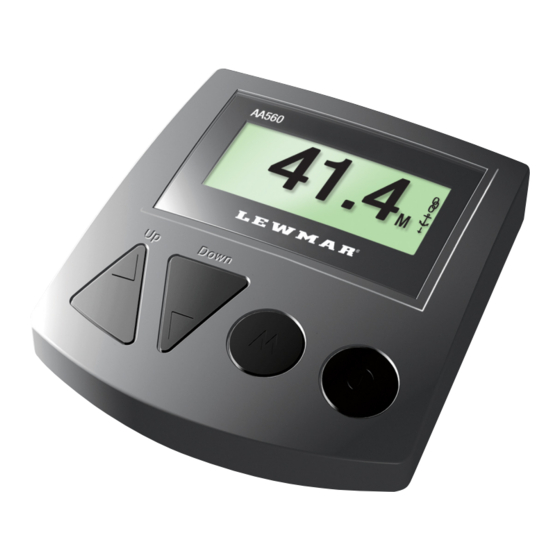
- Page 1 AutoAnchor 560 V2 OWNER’S MANUAL...
-
Page 2: Table Of Contents
AutoAnchor 560 Owner’s Manual TABLE OF CONTENTS Part 1 Important Information Part 2 Installation Part 3 Set Up Part 4 Operation Part 5 Maintenance Part 6 Troubleshooting Index To the best of our knowledge the information in this manual was correct at the time of printing. However, the AutoAnchor products are continuously being reviewed and improved and product specifications may be changed without notice. The latest product specifications may not be reflected in this version of the manual. -
Page 3: Important Information
PART 1 IMPORTANT INFORMATION TECHNICAL SPECIFICATIONS AA560 REAd BEFORE INSTALLING OR USING THE AUTOANCHOR Power Supply 12V/24V DC Maximum Voltage 30V DC • The AA560 should only be installed by a qualified marine electrician. Do not attempt to install the AA560 unless you are suitably qualified. Current Consumption 70mA •... -
Page 4: Part 2 Installation
PART 2 INSTALLATION Fitting the Sensor: Do not force the sensor into the hole. Hammering the sensor head can damage the internal electronics. Ensure the sensor head is positioned so that it will not be hit by the chainwheel during windlass operation and that it is at least 300mm (1ft) away 2.1 MAGNET ANd SENSOR INSTALLATION from the battery and motor cables. Secure the sensor using a good quality neutral cure silicone or a strong adhesive eg. Sikaflex 291 or 3M 5200. PLEASE REAd BEFORE COMMENCING INSTALLATION 2.1.3 PLUG ANd PLAy SENSOR CABLE Correct magnet and sensor installation is critical for successful AutoAnchor operation. - Page 5 dual Installation 2.1.6 INSTALLATION VERTICAL WINdLASS - CHAIN ONLy Refer to the Overview Notes on page 3 before starting installation. Use the T junction connector Part #9506 and the 2m (Male/Female) extension cable Part #9505. Note: If it is not possible to Part #9506 Chainwheel align the sensor and magnet Magnet exactly the AA grey sensor may be fitted up to 20mm out of...
- Page 6 2.1.7 INSTALLATION VERTICAL WINdLASS - ROPE & CHAIN 2.1.8 INSTALLATION HORIZONTAL WINdLASS - CHAIN ONLy Refer to the Overview Notes on page 3 before starting installation. Refer to the Overview Notes on page 3 before starting installation. It is not For an accurate rope and chain count, the rode must run between the sensor and possible to set out a single installation method for horizontal windlasses.
- Page 7 2.1.9 INSTALLATION HORIZONTAL WINdLASS - ROPE & CHAIN 2.2 CONSOLE INSTALLATION Before starting check with the AutoAnchor manufacturer, or supplier, that it is Choose a position where the operator will be able to see the anchor and windlass when possible to fit the sensor and magnet to your horizontal windlass. using the AA560. For an accurate rope count the rode must run between the sensor and magnet. On a horizontal windlass the magnet and sensor must be fitted by the windlass manufacturer. Mount on a flat surface at least 3ft (1m) away from any equipment or cables carrying radio signals eg VHF radios, cables and antennas or radar antenna and at least 6ft (2m) If it is not possible to have the sensor and magnet fitted to achieve this you can use the...
- Page 8 2.4 VOLTAGE LEVELS 2.5.1 MOTOR LOAd WIRES (BROWN ANd WHITE) FOR ROPE & CHAIN Neither the windlass nor the AutoAnchor will operate with insufficient power. (See minimum All-chain Counting: If the AA560 is fitted to an all-chain windlass the brown and white voltages below). Batteries must be properly maintained and charged and all connections wires are not required. and wires must be of good quality and the correct gauge to prevent voltage drop. Rope & Chain Counting: The brown and white wires must be connected for rope & chain counting. These wires are connected direct to the windlass motor terminals to measure Minimum Voltage Required 12V dC System...
-
Page 9: Part 3 Set Up
PART 3 SET UP 3.3 GENERAL SET UP To Access General Set Up 3.1 USING THE AUTOANCHOR BUTTONS Turn the AutoAnchor Off. Hold together to display the Set Up menu. Scroll: Menu/Numbers/Up/Down. Select General. Mode/Select/Enter/Save. To Exit General Set Up Exit to the Set up menu or hold for 2 seconds to exit On/Off/Escape or Back. - Page 10 3.5 WINdLASS SET UP 3.6.2 To Enter the Chain per Turn for Chain Only Rode For accurate counting you must set up the AutoAnchor with information for your windlass. Select Chain per turn. Setting: Record the settings for future reference. Enter the measurement. In mm or in metric inches mm or in metric inches (depending on units selected). See the table below for metric inch calculations. 3.5.1 To Access Windlass Set up Save and return to Rode Set up. Turn the AutoAnchor Off. Turn the AutoAnchor Off. Exit to Windlass Set up.
- Page 11 3.7.1 Selecting Use Preset 3.7.6 To Enter the Rope per Turn Setting: Setting: Refer to the Preset Windlass Profile List list in Appendix 1. Select Rope per turn. Enter the measurement in mm or metric inches in mm or metric inches Select Use Preset. (depending on the units selected). Select Windlass profile. Save and return to Rode Set up. There are no further Scroll to the correct Windlass profile for your windlass. settings.
-
Page 12: Part 4 Operation
3.10 dRUM WINCH SET UP PART 4 OPERATION Access via the Windlass Set Up Menu. 3 settings are AA560 BUTTONS required: Total Rode Length. Inside Diameter. Outside Diameter with rode retrieved. Sensor Pulse Indicator & Windlass Direction 3.10.1 To Access Windlass Set up Turn the AutoAnchor Off. Turn the AutoAnchor Off. - Page 13 4.2 USER PRECAUTIONS 4.4 AUTOMATIC ANd MANUAL OPERATION It is the owner’s sole responsibility to ensure the AutoAnchor is installed, used and Keep your finger on the button to deploy the anchor manually or use the automatic function maintained in a manner that will not cause accidents, personal injury or property damage. for hands free anchor deployment and retrieval. See the instructions for both options below. When using the AutoAnchor the operator must use safe boating practices and safe windlass/winch and anchoring operation For an accurate reading always ensure the AutoAnchor display reads 0.0 before •...
- Page 14 Safety Override 4.3 OTHER OPERATION SETTINGS Press any button on the AutoAnchor to stop the windlass during automatic release or Press to access the menu when the AutoAnchor is turned on. retrieval. In an emergency shut off the power to the windlass using the isolating/ breaker switch. 4.3.1 To Clear to Zero The AutoAnchor must be turned on. Enable Automatic Operation A “rode to be released” value must be entered to use automatic operation. Press to access the Menu. Select clear to zero. To Set A Rode to be Released Value Select No/Yes.
-
Page 15: Part 5 Maintenance
PART 5 MAINTENANCE TROUBLESHOOTING POSSIBLE CAUSE/ACTION MESSAGES Cont’d The AutoAnchor does not contain any user servicable parts. User maintenance is limited to: 3. Installation warning Appears when switching on the AutoAnchor. Go to Diagnostics for more information. • Checking all cables and connections for signs of wear or damage and replacing them as necessary. 4. Motor externally 1. Another control is being used for the windlass. • Checking the sensor head is not worn and has not moved out of alignment with the controlled. 2. Solenoid common ground is not connected or swapped with an magnet and replacing the sensor if necessary. After any sensor repairs or changes to up or down terminal. 3. Large voltage potential difference between AA560 Ground and sensor installation reset the sensor. See Page 24. Solenoid common ground. - Page 16 PART 7 TECHNICIAN dIAGNOSTIC INFORMATION OTHER TROUBLESHOOTING POSSIBLE CAUSE/ACTION Diagnostic messages help find an installation problem. The diagnostic messages are all 1. AutoAnchor beeps when it is turned off or 1. The unit beeps when it receives a sensor caused by external wiring, set up or installation issues which need fixing. They are not locked. pulse. This could be because the windlass caused by a fault with the AutoAnchor.
-
Page 17: Index
INdEX Sensor Installation diagnostic Messages Anchoring Magnet 3, 6-8 These messages appear when the AA560 is turned on. Go to the extended diagnostics for more information. After fixing the sensor installation retune the sensor. See page 21. Automatic 22-23 3, 6-8 Safety Override 3, 6-8 Red sensor wire... - Page 18 Set Up Backlight Check Logs Docking Distance Drum Winch General Key Beep Menu Overview Rode Sensor Units Use Preset Windlass 15-19 Specifications Technical Swap Control Technical Specifications Technician Diagnostics 28-29 Testing Troubleshooting 25-29 Units Set Use Preset User Precautions 1, 21 Vertical Windlass Magnet Installation Sensor Installation Voltage Windlass...
- Page 19 UK and International Distribution Lewmar Southmoor Lane Havant Hampshire PO9 1JJ England Tel: +44 23 9247 1841 Fax: +44 23 9248 5720 Email: info@lewmar.com Lewmar Incorporated 351 New Whitfield Street Guilford CT 06437 Tel: + 1 203 458 6200 Fax: + 1 203 453 5669 Email: info@lewmar.com...
Need help?
Do you have a question about the AutoAnchor 560 and is the answer not in the manual?
Questions and answers