Advertisement
Quick Links
Advertisement

Related Manuals for Lewmar 300 SVTAH


Summary of Contents for Lewmar 300 SVTAH
- Page 1 300 SVTAH Installation Manual Issue B...
- Page 2 THRUSTER INSTALLATION HYDRAULIC INSTALLATION FLUSHING PROCEDURE SPEED SENSOR INSTALLATION OPERATION MAINTENANCE CATHODIC PROTECTION SYSTEM TROUBLE SHOOTING TECHNICAL DATA SPARE PARTS MANUAL RAISE & LOWER OF THRUSTER THRUSTER DIMENSION DRAWINGS HYDRAULIC THRUSTER CIRCUIT DRAWINGS CONTROL PANEL DRAWINGS WARRANTY LEWMAR CONTACT DETAILS...
- Page 3 INTRODUCTION The thrust force created by a Lewmar Bow Thruster will cause a considerable suction on one side of the vessel and turbulence on the other. Care should be taken to ensure that there are no swimmers or divers in the vicinity of the vessel when the Thruster is operated.
- Page 4 INTRODUCTION Noise considerations. Because of the considerable power generated by a Lewmar Bow Thruster and the construction of most vessels there will be noise generated. It is also possible that the noise level will differ depending on the direction of thrust.
- Page 5 CLEANLINESS Contamination in hydraulic systems is the most frequent cause of malfunction or failure of hydraulic equipment. Depending upon the nature, size and amount of contamination it can lead to malfunction or serious loss of efficiency and reduced life of equipment. Particle contamination can be of metal, rubber, dirt, sand, paint etc.
- Page 6 CORROSION Sea water is both corrosive and conductive, so care should be taken to protect the underwater components of the Thruster. Under no circumstances should any equipment be electrically connected to the Thruster. The Thruster must not be used as an earth return and it should be noted that most hydraulic hoses contain wire braid reinforcement and are therefore conductive.
-
Page 7: Recommended Hydraulic Oil
RECOMMENDED HYDRAULIC OIL MANUFACTURER REFERENCE AGIP OSO 32 ARAL VITAM GF32 VITAM DE32 AVIA AVILUB RSL32 ENERGOL HLP32 ENERGOL HLP-D32 CASTROL HYSPIN AWS32 CHEVRON EP HYD. OIL 32 DEFROL HLP22 ESSO NUTO H 32 FINA HYDRAN 32 FUCHS RENOLIN MR10 RENLOIN B10 OPTIMOL HYDRO 5035... -
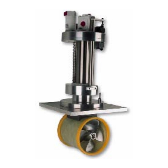
Page 8: Thruster Installation
THRUSTER INSTALLATION The 300 SVT is supplied on an aluminium base plate ready for mounting. The installer is responsible for the watertight integrity of the installation. As a general rule, the Thruster is installed with the propeller facing to starboard. When lifting the Thruster unit from its packing case, ensure that adequate lifting strops are used, and the unit is not lifted by its lead screw assembly or propeller shroud. - Page 9 THRUSTER INSTALLATION The upper limit switch can be finally set to isolate power to the raise mechanism as the hull closing plate seats. Ensure that the limit switch actually 'makes' when the Thruster is fully retracted, otherwise power will be left on the valve / motor applying unnecessary stress to the shroud / closing plate assembly.
-
Page 10: Installation
INSTALLATION Hydraulic Ensure that all pipe sizes / specifications conform to the information supplied on drawing No 51000099. Equipment should be accessible to allow for routine maintenance, oil changes etc. Keep tight bends and hose couplings to a minimum where ever possible. Where hoses pass through bulkheads or near sharp edges, ensure pipe clamps or additional shielding of the hose is undertaken to reduce the risk of chaffing. - Page 11 FLUSHING PROCEDURE GUIDELINES Flushing of the hydraulic system prior to start up is the single most important operation of the installation process. Failure to carry out sufficient system flushing will inevitably lead to rapid wear of components, contamination of valves and other hydraulic components which in turn may lead to product break down and failure as well as performance loss.
- Page 12 FLUSHING PROCEDURE GUIDELINES If possible the system should be flushed as a number of smaller sections by by - passing parts of the system using other lengths of tube and suitable adapters. Each section should be flushed for as long as possible.
- Page 13 INSTALLATION INSTRUCTIONS FOR PLC BASED SPEED SENSORS Oscillatory sensors are types of proximity detector. A transistor oscillator stops oscillating when metal objects approach the front of the sensor. This causes a change to the internal resistance of the sensor, which is detected by the electronics.
-
Page 15: Operation
OPERATION If there is a main circuit breaker fitted, ensure the breaker is closed. Switch on (enable) the system by pressing the main On / Off latching switch (Green), the switch will then be illuminated. The system will be live until the On / Off switch is unlatched by re-pressing the switch or the main power is removed. - Page 16 OPERATION Hydraulic (Non PLC Control Version, electric circuits 58400175 & 58400176) The Thruster is deployed by pressing and holding the down button and raised by pressing holding the up button, while the Thruster is in motion the button is extinguished. Once the Thruster is fully deployed or retracted the button will illuminate.
-
Page 17: Maintenance
MAINTENANCE In general very little maintenance of the Thruster is required. There are two grease nipples which supply grease to the raise / lower mechanism. One is located on the top plate, and one is on the main Thruster body. Apply 3 or 4 pumps from a grease gun every four to six months dependant on the Thruster usage, to ensure trouble free operation. - Page 18 MAINTENANCE CATHODIC PROTECTION SYSTEM When the boat is first commissioned it is important that the anodes are checked frequently at one month intervals. Check for signs of excessive corrosion. If the anode has corroded significantly, then renew immediately. If the anodes/unit shows signs of corrosion shortly after commissioning then it is important that the vessels electrical system is checked for earth leaks, or other electrical faults that are possibly accelerating the corrosion process.
-
Page 19: Troubleshooting
TROUBLE SHOOTING No Power at Thruster Check main circuit breaker (if fitted) is on, reset or replace if blown. Check the control circuit fuses are not blown, replace if necessary. In the above cases when the On / Off switch is operated the switch will not illuminate. If power is available to the motor but the propeller will not turn, check the propeller is not fouled / obstructed with rope or timber etc. - Page 20 TROUBLE SHOOTING Raise / Lower system non operative] Check hydraulic power to the raise / lower motor. Ensure there is no mechanical obstructions inside or externally restricting movement. All SVT Thrusters have a manual override to the raise / lower system (See Manual Raise / Lower Data Sheet).
- Page 21 300 SVT THRUSTER TECHNICAL DATA Thruster Type:- 300 SVTAH HP:- 15,20,25 & 30 hp Stroke Length Length :- 350 mm Main Hydraulic Motor Type:- Reversible Gear Motor Capacity :- 15hp = 23 cc / rev 20hp = 27 cc / rev...
- Page 23 ITEM NO PART NO DESCRIPTION B7729 Hyd Motor (Raise & Lower) B7738 Hyd Motor (15hp) B7735 Hyd Motor (20hp) B7736 Hyd Motor (25hp) B7734 Hyd Motor (30hp) B0686 M8 x 20 Skt Hd Cap Screw B8033-A4 M10 x 45 Skt Hd Bolt B1232 M10 Spring Washer B1208...
- Page 24 ITEM NO PART NO DESCRIPTION B7883 O Ring 44b,75a B2419 M6 Helicoil 55000940 Spacer 55000941 Plain Bearing 55000840 Mounting Plate 55000862 Retaining Collets B1230 M6 Spring Washer B1201 M6 Flat Washer B0687 M8 x 25 Skt Hd cap Screw 55000802 Shroud Plate 55000083 Shroud Support Strut...
- Page 25 MANUAL RAISE & LOWER OF THRUSTER If the Thruster cannot be raise or lowered using Electrical or Hydraulic power, it is possible to raise or lower the unit mechanically. Remove the 2 x M6 leadscrew locking bolts from the base plate using a 5 mm allen key.
- Page 43 LEWMAR LIMITED WARRANTY Lewmar warrants its products in normal usage to be free of defects in materials and workmanship for a period of three years from date of purchase by the original purchaser, subject to the conditions, limitations and exceptions listed below. Any part, which proves to be defective in normal usage during that three-year period, will be repaired or at Lewmar’s option, replaced by Lewmar.
- Page 44 LIABILITY Lewmar's liability under this warranty shall be to the exclusion of all other warranties or liabilities (to the extent permitted by law). In particular (but without limitation): Lewmar shall not be liable for: - Any indirect or consequential loss including (without...
- Page 45 Tel (+33) 5 46 50 50 46 Fax (+33) 5 46 50 59 04 e-mail info@france.lewmar.com Lewmar Southern Europe (Cannes) Lewmar Ltd, Allée Charles Nungesser, Parc D’Activités de la Siagne 06210 Mandelieu, France Tel (+33) 4 93 48 80 48 Fax (+33) 4 93 48 37 50 e-mail info@france.lewmar.com...
Need help?
Do you have a question about the 300 SVTAH and is the answer not in the manual?
Questions and answers