Table of Contents
Advertisement
Advertisement
Table of Contents

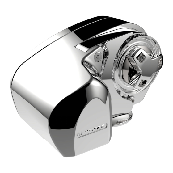
Summary of Contents for Lewmar Pro Series
- Page 1 ar.com...
-
Page 2: Table Of Contents
3.5 Letting go under power To the best of our knowledge, the information in this manual was correct when it went to press. However, Lewmar cannot 3.6 Change Pro-Fish to power down mode accept liability for any inaccuracies or omissions it may contain. -
Page 3: Introduction
Throughout this manual, you will see safety and product damage world renowned for their quality, technical innovation and proven warnings. You must follow these warnings carefully to avoid performance. With a Lewmar windlass you will be provided with possible injury or damage. many years of outstanding service. -
Page 4: Installation
1. Installation 1.4 Accessories • Pro-Series & Pro-Fish Manual Use only Lewmar parts and accessories to ensure top performance All references regarding installation and wiring and eliminate the risk of voiding your warranty. For replacement etc. of Pro-Series apply to the equivalent parts, please see the Parts section or visit your nearest dealer or Pro-Fish model (700 or 1000). - Page 5 Fig. 1.6.2 Fig. 1.6.5 12” (300 mm) min. • Next, using the wrench on the fl ats, tighten the studs until • Place the mounting template on the deck or mounting pad in they bottom out in their holes. Do this to each of the studs in the desired position for the windlass and hold it in place using turn.
-
Page 6: Electrical Wiring Installation
2. Electrical wiring installation 2.1 Electric cable selection 2.2 Wiring To achieve the best performance and to safeguard your electrical Plan the installation to suit the controls and give the operator a full system it is essential that any electrical windlass be fi tted with view of the windlass. -
Page 7: Model 700
2.3 Model 700 - 12 V Choice of cable thickness depends on total cable length: Model Motor Breaker / Isolator Contactor A + B + C + D + E = 12 V 50 A (68000348) Batter y to windlass, windlass to batter y. 1000 12 V 70 A (68000240) -
Page 8: Model 1000
2.4 Model 1000 - 12 V Fig. 2.4.1 DECK HAND FOOT SWITCH HELD GUARDED CONTROL ROCKER 68000598 Black SWITCH 68000599 68000597 White 68000593 DOWN Shared Down CIRCUIT Fuse BREAKER/ISOLATOR 68000240 - 70 A, 12 V CONTACTOR 0052531 - 12 V BATTERY A + B + C + D + E = 12 V... -
Page 9: Operating Your Windlass
3. Operating your windlass As a prudent act of seamanship, anchor recovery operations 3.8 Hauling in require the undivided attention of skipper and crew to prevent Untie the bridle or replace the rode in the gypsy. If it is safe to do personal injury or damage to the vessel. -
Page 10: Maintenance
4. Maintenance 4.1 General recommendations • Examine all electrical connections for possible corrosion, clean and lightly grease as necessary. Isolate the windlass electrically, before carrying out any • Anchor rode splice should be checked regularly and remade maintenance work. if there is any evidence of wear. •... -
Page 11: Electric Motor Replacement
5.5 Electric motor replacement Isolate the windlass electrically! Disconnect the Motor Cables from the vessel’s wiring loom. Remove the Gear Train Cover (17) using a 4 mm ( ”) Allen Wrench as detailed above. Remove the 1st Compound Gear Assembly (16) and Tefl on™ Flat Washers (14). Using a 4 mm ( ”) Allen Wrench remove the Motor Screws (10). -
Page 12: Service Kits
6.1.1 Parts list 6.2 Pro-Series & Pro-Fish models 700 & 1000 service kits Service Kit Description Items Included (Qty) 66000096 Pro-Series Stripper Arm Kit 4(1), 10(2), 31(2) 66000097 Control Arm Kit 6(1), 7(1), 8(1), 33(1), 34(1) 66000098 Pro-Series Clutch Nut & Cone Kit 1(1), 2(1), 28(2) 66000099 Clutch Lever... -
Page 13: Troubleshooting
Check the contactor coil ground circuit. If okay, replace the terminal on the contactor? contactor. Check the voltage at the motor. If voltage is present, the motor is defective. If you have any questions call your nearest Lewmar representative. Pro-Series & Pro-Fish Windlass... -
Page 14: Lewmar Limited Warranty
Notice of a claim for service under this warranty shall be made promptly ii Responsibility for the selection of products appropriate for the use and in writing by the end user to the Lewmar outlet which supplied the intended by the Buyer shall rest solely with the Buyer and Lewmar product or to Lewmar at Southmoor Lane, Havant, Hampshire, England accepts no responsibility for any such selection. - Page 15 © Copyright 2006 Lewmar Ltd. All rights reserved. B10490 Produced by T. Connell UK (+44) 023 9263 9265 Ref:T1954/05/2006...


Need help?
Do you have a question about the Pro Series and is the answer not in the manual?
Questions and answers