
Related Manuals for Lewmar VX Series


Summary of Contents for Lewmar VX Series
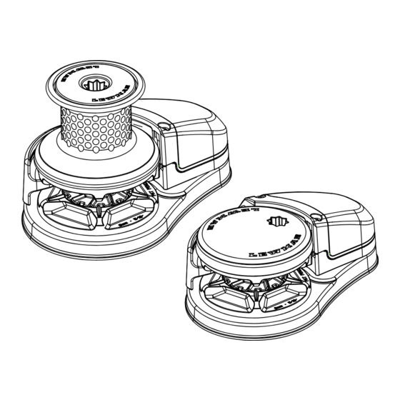
- Page 1 Lewmar VX Vertical Windlasses 65100045 Issue 9 Owners Installations, Operation & servicing manual...
-
Page 2: Product Support
With a Lewmar product you will be provided with many years of outstanding service. Product support Lewmar products are supported by a worldwide network of distributors and Authorised Service Representatives. If you encounter any difficulties with this product, please contact your national distributor, or your local Lewmar dealer. CE Approvals For CE approval certificates contact Lewmar. -
Page 3: Safety Notice
• Boating, like many other activities can be hazardous. Even the correct selection, maintenance and use of proper equipment cannot eliminate the potential for danger, serious injury or death. • Lewmar windlasses are designed and supplied for anchor control in marine applications and are not to be used in conjunction with any other use. -
Page 4: Installation
• Crimping Pliers / Wire Stripper • Suitable electrical cable and crimp terminals 3.2 Accessories Use only genuine Lewmar parts and accessories to ensure top performance and eliminate the risk of voiding your warranty. 3.3 Gypsy Suitability Gypsies fitted to the VX range of windlasses are ideally suited to handling our factory made Rope/Chain combination rodes, which consist of rope spliced to a chain tail. - Page 5 The deck is an integral component of the windlass it has to secure the windlass and be strong enough to cope with the high torque stresses involved in recovering the anchor. • Lewmar recommends a minimum deck thickness of 40mm (11/2”). Note: For thicker deck, a longer 3.5-1...
- Page 6 3.6 Below deck preparation IMPORTANT: The positioning of the windlass must be checked prior to cutting for deck/hull and bulkhead clearance. 3.6-1 1.The motor/gearbox is bolted via the through deck mounting bolts. NOTE: Do not position motor/gearbox below rode/chain pipe fall area. 3.6-2 300 mm (12”)
- Page 7 3.7 Above deck fitting 1. Lead from the roller should be fed horizontally back 3.7-1 to the top of the gypsy and along its centre line within ±5˚. ±5° 2. Using your template and after you have checked all the above and below deck requirements cut the following holes.
- Page 8 5. Place the base mat in position on the deck. 3.7-5 Optionally, apply a suitable sealant to the base of the windlass, any mounting pad or around the studs. NOTE: If using silicone or other rubbery type sealant, it is advisable to allow curing of the sealant before final tightening of the mounting nuts.
- Page 9 ⚠ WARNING! Isolate the windlass using circuit breaker/isolator. For safety and performance Lewmar recommends the use of matched Lewmar anchor rodes. 1. Remove cover. 2. Pull out control arm. 3. Feed anchor rope/chain into entry hole. Tie off to suitable strong point.
- Page 10 ⚠ WARNING! Isolate the windlass using circuit breaker/isolator. For safety and performance Lewmar recommends the use of matched Lewmar anchor rodes. 1. Remove cover. 2. Pull out control arm. 3. Feed anchor rope/chain into entry hole. Tie off to suitable strong point.
- Page 11 68000968 NOTE: In a multi station installation all switches must be wired in a parallel circuit. 4.4 Electric motor terminal connections ‣ When wiring Lewmar electric motor DO NOT overtighten electric motor terminal nuts. into the ship’s electrical system the following caution must be taken.
- Page 12 4.5 VX1 - Wiring diagram using contactor provided (Part No 68000939) Installation instructions are supplied separately with any accessories. Switch wire thickness:1.5 mm2 (16 AWG) Optional accessories Remote Handheld Control Electric Switches Reed Switch Sensor DOWN Rocker Switch for chain (68000593) counter (if fitted)
- Page 13 4.6 VX1 - Wiring diagram if a contactor box (Part No 68000965) is used Installation instructions are supplied separately with any accessories. Optional accessories Remote Handheld Control Electric Switches DOWN Rocker Switch (68000593) Reed Switch Sensor for chain counter Fuse (if fitted) DOWN Contactor Box...
- Page 14 4.7 VX1L - Wiring diagram using contactor provided (Part No 68000939) Installation instructions are supplied separately with any accessories. Optional accessories Remote Handheld Control Electric Switches Reed Switch Sensor DOWN Rocker Switch for chain counter (68000593) (if fitted) DOWN Fuse Optional Wire- less Control Available(See §...
- Page 15 4.8 VX1l - Wiring diagram if a contactor box (Part No 68000965) is used Installation instructions are supplied separately with any accessories. Optional accessories Remote Handheld Control Electric Switches DOWN Rocker Switch (68000593) Reed Switch Sensor for chain counter Fuse (if fitted) DOWN Contactor Box...
- Page 16 4.9 VX2/3 Wiring diagram Installation instructions are supplied separately with any accessories. Electric Deck Switches DOWN MOTOR Rocker Switches BATT DOWN MOTOR Fuse Thermal Switch Control Box Electric Remote Control Battery Isolator Circuit Breaker Battery 12/24 VDC MOTOR D2 MOTOR D1 1.
- Page 17 • Adjust rate of fall with handle. Once paid out fully tighten gypsy drive cap. Gypsy/drum • Place a Lewmar handle into the drum top nut and operate as gypsy version above. ⚠ WARNING! Isolate the windlass using circuit breaker/isolator.
-
Page 18: Power Up/Down
5.2 Power up/down To release anchor. 1. Release any anchor locks. 2. When safe, operate DOWN control. To retrieve anchor. • Retrieving the anchor is the reverse to the above. • When safe, operate the UP control. • Once anchor is retrieved, ensure it is adequately secured to an independent strong point. 5.2-1 5.2-2 5.3 Optional manual recovery kits (VX2/3 ONLY) - Page 19 5.4 Independent warping Gypsy/drum only 5.4-1 1. Lock anchor chain before warping. 2. Place a Lewmar winch handle into top nut. Disengage clutch by turning anti-clockwise by half a turn. Remove handle. 3. When safe, operate the drum. If warping speed is too fast, ease tension in rope.
-
Page 20: Operating Tips
5.5 Operating tips Vessels at anchor will snub on the rode and this can cause slippage or apply excessive loads to the windlass. 1. When anchoring, power rode out allowing the vessel to take up stern away preventing the rode tangling with anchor. -
Page 21: Servicing Schedule
6. Servicing ⚠ WARNING! Ensure rode is ⚠ WARNING! Isolate the adequately secured to an windlass using circuit independent strong point. breaker/isolator. 6.1 Servicing schedule Regularly: Annually: • Wash down the windlass using fresh water. • Check electric cables for damage. Repair/renew as required. - Page 22 4. Remove gypsy from windlass 6.2-4 6.2-5 5. If replacing lower cone and washer (included in Gypsy replacement kit), remove the cone retaining circlip from the shaft and lift off the cone and washer from the windlass. Assemble the new gypsy in reverse order, note that the part number engraved on the stripper ring should face upwards.
- Page 23 6.4 VX2/3 Gypsy replacement/service 6.4-2 6.4-1 ⚠ WARNING! Isolate the windlass using circuit breaker/isolator. 1. Remove chain cover screw using 5mm allen key 2. Pull control arm out and lift chain cover and control arm assembly from deck unit. 3a. Gypsy only 6.4-3a 6.4-3b Using windlass handle remove top...
-
Page 24: Parts List
7. Parts List 7.1 Parts list VX1 34 35... - Page 25 7.1 Parts list VX1 VX1 PARTS LIST KIT NO. KIT DESCRIPTION ITEMS INCLUDED (QTY.) 66000799 Windlass handle 1(1) 66100120 VX1 Gypsy Only top cap kit 2(1) 66100121 VX1 Base kit 9(1), 10(1), 11(1), 30(1), 31(4) 23(1), 24(1), 25(1), 26(1), 27(1), 28(1), 29(1), 66100123 VX1 Chain cover and control arm kit 32(1), 33(1)
- Page 26 7.2 Parts list VX2/3 9 10 11 12 24 25 26 27 28 29...
- Page 27 7.2 Parts list VX2/3 VX2/3 PARTS LIST KIT NO. KIT DESCRIPTION ITEMS INCLUDED (QTY.) 66000799 WINDLASS HANDLE 1(1) 66120001 VX2/3 GO TOP CAP REPLACEMENT 3(1) 66120002 VX2/3 BASE KIT 8(1), 14(1), 16(1), 18(1), 34(1), 35(4), 37(1), 42(1) 66120003 VX2/3 CHAIN COVER KIT 39(2), 40(1) 66120004 VX2/3 CONTROL ARM KIT...
- Page 28 7.3 Parts list VX1L 19 20 21 22...
- Page 29 7.3 Parts list VX1L VX1L PARTS LIST KIT NO. KIT DESCRIPTION ITEMS INCLUDED (QTY.) 66000799 WINDLASS HANDLE 1(1) 66100120 VX1 GO TOP CAP KIT 2(1) 66100122 VX1L BASE UNIT 10(4), 11(1), 12(1), 28(1), 29(4) 30(1), 31(1), 32(1), 33(1), 34(1), 35(1), 36(1), 37(1), 66100123 VX1 CHAIN COVER &...
- Page 30 8. Specifications 8.1 VX1 Dimensions (mm) (inch) (mm) (inch) (mm) (inch) 6 mm ISO 4565 0.236 0.709 21.6 0.85 6mm Din766 0.236 18.5 0.728 20.4 0.803 68100034 12-16 mm (1/2 - 5/8”) 7mm ISO 4565 0.276 0.826 0.905 3 Strand and 8 Plait 7mm Din766 0.276 0.866...
- Page 31 26.2 1.030 29.7 1.168 3 Strand and 8 Plait 8 mm DIN 766 0.315 0.945 27.2 1.070 Lewmar 9.5mm G40 0.374 1.102 1.260 12-16 mm (1/2 - 5/8”) 5/16” Campbell S3 0.315 1.260 1.102 68120042 3 Strand and 8 Plait 3/8”...
- Page 32 8.3 Deck template guide DO NOT use this template as a cutter. It is supplied as a guide only. Check before drilling holes. VX1 Deck Mounting Detail BASE MATTT OUTLINE 4 HOLES Ø10 Ø67 Ø14 Ø40 ANCHOR RODE CENTRELINE Ø18 VX2/3 Deck Mounting Detail Ø62 4 HOLES...
-
Page 33: Electric Specifications
VX1L Deck Mounting Detail BASE MATT OUTLINE 5 HOLES Ø15 3 HOLES Ø10 Ø67 Ø100 ANCHOR RODE CENTRELINE 8.4 Electric specifications POWER MODEL MOTOR TYPICAL MAX. PULL MAXIMUM LINE SPEED TYPICAL WORKING LOAD OPTION M/MIN FT/MIN 1488 1433 VX1L VX1L 2028 1874 1874... -
Page 34: Troubleshooting
9. Trouble shooting 9.1 Electric windlass 1. Anchor rode pays out independently while windlass is not in use. This problem is a result of not securing the anchor rode combined with the gypsy drive cap being slack. Tighten the gypsy drive cap using the winch handle and always secure the anchor rode independently of the windlass when not in use.
Need help?
Do you have a question about the VX Series and is the answer not in the manual?
Questions and answers
Ref Lewmar VX3 - Pages 26 & 27 parts list - I **** reassembling the windlass with new top section. I **** trying to identify the individual washers (white Teflon and metal, also circling / positions on the shaft relative to the other parts but the diagram with its numbers are not individually named on page 27 (packaged together) - can you assist please. Regards
For the Lewmar VX3 windlass reassembly, follow these steps to identify washers and their positions:
1. Gypsy Only Assembly:
- Remove the top cap using the windlass handle.
- Take off the washer and upper cone from the shaft.
2. Gypsy/Drum Assembly:
- Undo the drum top cap with the windlass handle.
- Remove the drum, drum washer, upper cone washer, and upper cone from the shaft.
During reassembly, place the washers back in the reverse order of removal:
- Drum Washer goes between the drum and upper cone washer.
- Upper Cone Washer sits above the drum washer.
- Standard Washer fits between the top cap and upper cone.
Ensure all components are clean and properly greased before reassembly.
This answer is automatically generated