
Related Manuals for Lewmar V1/Sport


Summary of Contents for Lewmar V1/Sport
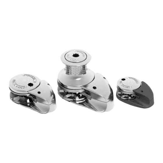
- Page 1 Lewmar V1-6 & Sport Windlass 65001201 Issue 2 Owner’s Installation, Operation & Basic Servicing Manual...
-
Page 2: Table Of Contents
• This product requires installation other use. by a suitably qualifi ed electrical engineer. Lewmar V1, V2, V3 & SPORT Windlass | 2... -
Page 3: Installation
For replacement parts, take up camber or sheer. please visit your dealer or the Lewmar • NOTE: If in doubt about the suitable web site. construction of the pad consult a 3.3 Gypsy Suitability... -
Page 4: V1-6 Deck Thickness
40-66 mm (1 ”- ”). 3. Model V6 • Lewmar recommends a minimum deck thickness of 40 mm (1 ”). M10 studs suit deck and packing thickness of 40-56 mm (1 ”- ”). Lewmar V1-6 & SPORT Windlass | 9... -
Page 5: V1-6 Bellow Deck Preparation
Chain from the roller should be fed horizontally back to the top of the gypsy and along its centre line within ±5˚. There must be suffi cient vertical fall for the chain when hauling in. Lewmar V1-6 & SPORT Windlass | 10... -
Page 6: V1-6 Above Deck Fi Tting
3. Assemble and tighten studs into base until they bottom out in their holes. Some studs have a fl at. Position the fl ats of the studs nearest the base of the windlass. Lewmar V1-6 & SPORT Windlass | 11... -
Page 7: V1-3 Under Deck Fi Tting
2. Open up the Fast Fit clamp and offer the gearbox up to the above deck unit, sliding the shaft into the gearbox. Ensure the drive key is in place. Lewmar V1-6 & SPORT Windlass | 12... -
Page 8: V4-5 Under Deck Fi Tting
M8 Nyloc nut. • NOTE: If using silicone or other rubbery type sealant, it is advisable to allow curing of the sealant before fi nal tightening of the mounting nuts. Lewmar V1-6 & SPORT Windlass | 13... -
Page 9: V6 Under Deck Fi Tting
Assemble the M10 bolts secure with Loctite ® threadlock to 43 Nm torque. • NOTE: Position the motor/gearbox away from the rope/chain pipe fall. Lewmar V1-6 & SPORT Windlass | 14... -
Page 10: V1-6 Loading Rope/Chain
5. Power load rest of anchor rope/ chain. • Model V6 chain only These models have the same loading procedure as above but do not have a control arm. Lewmar V1-6 & SPORT Windlass | 15... -
Page 11: Electrical Wiring
Wireless remote 5 button windlass and thruster • NOTE: Wireless remote also available. • NOTE: Wireless remote can only be used if a contactor is fi tted. See wireless remote instructions for 68000967 68000968 wiring details. Lewmar V1-6 & SPORT Windlass | 17... -
Page 12: V1-6 Wiring Diagram
12/24 VDC MOTOR MOTOR D2 MOTOR −V −V MOTOR MOTOR D1 −V MOTOR Contactor Contactor Contactor • NOTE: Motor connections D1 = F1 D2 = F2 • Switch wire thickness: 1.5 mm (16 AWG) Lewmar V1-6 & SPORT Windlass | 18... -
Page 13: Hydraulic System
A & B ports ½” BSP. directional valve is being used. • NOTE: Refer to your installed • NOTE: To permanently sustain a load hydraulic system manual for a Chain Stopper must be used. hydraulic drives. Lewmar V1-6 & SPORT Windlass | 20... -
Page 14: Operation
4. Adjust rate of fall with handle. Once paid out fully tighten gypsy drive cap. Gypsy/drum 5. Place a Lewmar handle into the drum top nut and operate as gypsy version above. WARNING! Always remove winch handle after use. -
Page 15: Power Up/Down
• NOTE: Remember, on models V1-3 the fall-safe does need to be disengaged before anchor can be let go again. • Once anchor is retrieved, ensure it is adequately secured to an independent strong point. Lewmar V1-6 & SPORT Windlass | 22... -
Page 16: V1-3 Manual Recovery
• Sport versions These units have no manual recovery. 1. Engage fall safe pawl. 2. Place a Lewmar winch handle into gypsy drive cap/drum top nut and rotate anti-clockwise by half a turn. 3. Remove handle and place into the bi-square in the cap and rotate clockwise. -
Page 17: V2-6 Independent Warping
2. Models V2-3 Engage fall safe pawl. Models V4-5 Check pawl is in disengaged position. 3. Place a Lewmar winch handle into top nut. Disengage clutch by turning anti-clockwise by half a turn. • Remove handle. 4. When safe, operate the drum. -
Page 18: Operating Tips
• Scope: As a guide it is recommended that the depth of chain to rope is 7 to 1 at anchor. Lewmar V1-6 & SPORT Windlass | 25... -
Page 19: V1-6 Gypsy Replacement/Service
2. Remove screw from inner edge of and remove drum assembly to get to fall-safe pawl. gypsy. • Lift off pawl and replace components. Lewmar V1-6 & SPORT Windlass | 27... -
Page 20: V1 Parts List
V Range Gypsy & Stripper Kit (000) 31(1), Magnet(1) 68000361 V Range Gypsy & Stripper Kit (001) 31a(1), Magnet(1) 68000362 V Range Gypsy & Stripper Kit (002) 31b(1), Magnet(1) 68000840 V Range Gypsy & Stripper Kit (006) 31c(1), Magnet(1) Lewmar V1-6 & SPORT Windlass | 29... -
Page 21: V2 & V3 Parts List
Assembly 12 V V3 M/O Ride Motor Gearbox 68000819 30(1), 36(1), 37(1) Assembly 24 V V3 M/O Ride Motor Gearbox 68000820 30(1), 36(1), 37(1) Assembly V2/3 Gypsy/Drum Manual 66840056 Not Shown Recovery Kit Lewmar V1-6 & SPORT Windlass | 30... -
Page 22: V4 & V5 Parts List
Hex Keys 4, 5 & 6 mm 66200076 Optional Sensor & Magnet Sensor(1), Magnet(1) & Housing(1) 'G' SHAFT 'GD' SHAFT 66810031 CONTROL ARM KIT 66200076 SENSOR & MAGNET KIT SENSOR MAGNET SENSOR HOUSING SENSOR Lewmar V1-6 & SPORT Windlass | 31... -
Page 23: V6 Parts List
66000678 Mainshaft (Gypsy/Drum) 14(1), 15(1), 16(1), 17(2) 66000677 R/H Chain Cover 13(1), 12(2) 66000676 L/H Chain Cover 11(1), 12(2) 66000675 Mounting 7(6), 8(1), 9(6), 10(6) 66000674 Base 1(1), 2(1), 3(1), 4(6), 5(1), 6(1) Lewmar V1-6 & SPORT Windlass | 32... - Page 24 10 mm ISO 4565 0.394 1.181 1.417 68000363 16 mm ( ”) ” Campbell S3 0.394 34.5 1.358 34.5 1.358 Gypsy No. 003 3 Strand and 8 Plait Lewmar 9.5mm G30/G40 0.374 1.102 1.260 Model Lewmar V1-6 & SPORT Windlass | 33...
- Page 25 34.5 1.358 34.5 1.358 12 mm ISO 4565 0.472 1.142 43.2 1.701 68000359 18-20 mm ( ”) Gypsy No. 204 3 Strand and 8 Plait 13 mm DIN 766 0.512 1.142 1.850 Model Lewmar V1-6 & SPORT Windlass | 34...
- Page 26 0.519 68000906 ” Gypsy Kit Lewmar 12 mm G30/G40 0.472 1.417 40.5 0.472 Lewmar 14 mm G30/G40 0.551 1.654 0.551 68000905 14 mm Gypsy Kit 14 mm DIN 766 0.551 1.614 0.511 Model Lewmar V1-6 & SPORT Windlass | 35...
-
Page 27: V1-6 Deck Template Guide
”) PCD 160 mm (6 ”) Ø5 mm ( ”) Ø77 mm (3”) PCD (45°) 120 mm (4 ”) Ø14 mm ( ”) 47.5 mm (1 ”) Ø12 mm ( ”) 55 mm (2 ”) Lewmar V1-6 & SPORT Windlass | 36... -
Page 28: Electric Specifi Cations
1000 V1 MO 1000 48.5 1433 48.5 1675 24.5 1000 1962 21.5 24.5 1000 1020 2248 21.5 1600 1360 2998 2000 1600 3528 2000 1860 4100 2000 2000 4410 2000 1800 3960 Lewmar V1-6 & SPORT Windlass | 37... -
Page 29: Trouble Shooting
1. No power to Commander • Refer to fault diagnostic charts in • Check unit is switched on the Commander manual. • Check electrical connections to Commander • Check fuses & safety cut-outs Lewmar V1-6 & SPORT Windlass | 38... - Page 30 Lewmar shall not be liable in any way for Product failure, or any state or country’s law, shall be limited to a period of one year from resulting loss or damage that arises from: the date of purchase by the end user.
Need help?
Do you have a question about the V1/Sport and is the answer not in the manual?
Questions and answers