Furuno TZTL12F Installation Manual
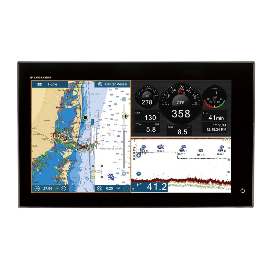
Multi function display
Hide thumbs
Also See for TZTL12F:
- Operator's manual (278 pages) ,
- Installation manual (69 pages) ,
- Software update procedure (12 pages)
Table of Contents
Advertisement
Installation Manual
Multi Function Display
Model TZTL12F/TZTL15F
SAFETY INSTRUCTIONS ................................................................................................ i
SYSTEM CONFIGURATION ........................................................................................... ii
EQUIPMENT LISTS........................................................................................................ iii
1. MOUNTING..............................................................................................................1-1
1.1 Mounting Considerations ...................................................................................................1-1
1.2 Flush Mounting ..................................................................................................................1-2
1.3 Retrofit Kit for TZTL12F (option) and Front Fixing Panel Kit for TZTL15F (option) ...........1-3
1.4 Desktop Mounting (option).................................................................................................1-4
1.5 Installation of Transducers.................................................................................................1-6
1.6 Installation of Sensors (option) ........................................................................................1-16
2. WIRING....................................................................................................................2-1
2.1 Interface Connections (Rear of Unit) .................................................................................2-1
2.2 How to Secure and Waterproof Connections.....................................................................2-2
2.3 MULTI Cable......................................................................................................................2-2
2.4 Network Connector ............................................................................................................2-5
2.5 Video In, Video Out and USB Connections .......................................................................2-5
2.6 CAN bus (NMEA2000 Connector) .....................................................................................2-6
2.7 Example NavNet TZtouch2 System Configurations.........................................................2-10
3. HOW TO SET UP THE EQUIPMENT......................................................................3-1
3.1 How to Set Time Zone and Language ...............................................................................3-3
3.2 How to Set Units of Measurement .....................................................................................3-4
3.3 Initial Setup ........................................................................................................................3-5
3.4 How to Set Up the Radar ...................................................................................................3-9
3.5 How to Set Up the Sounder .............................................................................................3-11
3.6 Wireless LAN Setting .......................................................................................................3-16
APPENDIX 1 INSTALLATION OF TEMPERATURE SENSORS ............................AP-1
PACKING LISTS ......................................................................................................... A-1
OUTLINE DRAWINGS ................................................................................................ D-1
INTERCONNECTION DIAGRAM ................................................................................ S-1
www.furuno.com
All brand and product names are trademarks, registered trademarks or service marks of their respective holders.
Advertisement
Table of Contents

Subscribe to Our Youtube Channel
Related Manuals for Furuno TZTL12F


Summary of Contents for Furuno TZTL12F
-
Page 1: Table Of Contents
EQUIPMENT LISTS......................iii 1. MOUNTING......................1-1 1.1 Mounting Considerations ....................1-1 1.2 Flush Mounting ........................1-2 1.3 Retrofit Kit for TZTL12F (option) and Front Fixing Panel Kit for TZTL15F (option) ...1-3 1.4 Desktop Mounting (option)....................1-4 1.5 Installation of Transducers....................1-6 1.6 Installation of Sensors (option) ..................1-16 2. - Page 2 (Elemental Chlorine Free) The paper used in this manual is elemental chlorine free. FURUNO Authorized Distributor/Dealer 9-52, Ashihara-cho, Nishinomiya, 662-8580, JAPAN A: JAN. 2015 All rights reserved. Printed in Japan Pub. No. IME-44870-A (GREG) TZTL12F/TZTL15F 00019007410...
-
Page 3: Safety Instructions
Connection of an incorrect power Steering Standard supply can cause fire or damage Model compass compass the equipment. 0.75 m 0.50 m TZTL12F 0.75 m 0.45 m TZTL15F... -
Page 4: System Configuration
FA-30/50 HUB -101 SC-30 FAX-30 GP-330B FUSION-Link Equipment* FI-5002 FI-50/70 NAVpilot-700 IF-NMEA2K1/2 Multi Function Display* Multi Function Display* TZTL12F TZTL12F Remote Controller Wide Monitor MCU-002 CCD Camera TZTL15F TZTL15F CCD Camera SD Card Unit SDU-001 Event SW Transducer External Buzzer... -
Page 5: Equipment Lists
EQUIPMENT LISTS Standard supply Name Type Code No. Remarks TZTL12F Multi Function Display TZTL15F CP19-01800 000-027-063 For TZTL12F Installation Materials CP19-01900 000-027-064 For TZTL15F Accessories FP19-02011 001-337-390 Spare Parts SP19-00601 001-023-040 Fuses (Type: FBG0-A 125V 5A PBF, Code: 000-155-853-10, 2 pcs.) - Page 6 Thru-hull type, plastic Temperature Sensor T-04MSB 000-026-893 Thru-hull type T-04MTB 000-026-894 Transom mount Bracket 12 OP19-13 001-337-410-00 For TZTL12F Bracket 15 OP19-14 001-337-420-00 For TZTL15F Retrofit Kit For VX2 OP19-15 001-337-430-00 For TZTL12F 10.4" Retrofit Kit For MDF12 OP19-16 001-337-440-00...
-
Page 7: Mounting
MOUNTING Mounting Considerations TZTL12F TZTL15F When selecting a mounting location for NavNet TZtouch2, keep the following in mind: • The temperature at the mounting location shall be between -15°C and +55°C. • The humidity at the mounting location shall be 93% or less at 40°C. -
Page 8: Flush Mounting
Note: Ensure the mounting location is flat, with no indents or protrusions, to allow a secure fit. 1. Prepare a cutout in the mounting location using the template (supplied) for the TZTL12F or TZTL15F. 2. Attach the flush mounting sponge, in the order indicated in the figure to... -
Page 9: Retrofit Kit For Tztl12F (Option) And Front Fixing Panel Kit For Tztl15F (Option)
Mounting panel Retrofit Kit for TZTL12F (option) and Front Fixing Panel Kit for TZTL15F (option) When upgrading to the TZTL12F or front-mounting the TZTL15F, use the kit which matches your old equipment. (Refer to the table below for details.) Optional kit Code No. -
Page 10: Desktop Mounting (Option)
Desktop Mounting (option) Follow the appropriate procedure below to mount the TZTL12F or TZTL15F. 1.4.1 How to mount the TZTL12F Use the optional kit Bracket12 (contents shown below), for mounting the TZTL12F. Type Code Contents Knob bolt 2 (Code No.: 100-365-900-10), Self-tapping... - Page 11 1. MOUNTING 1.4.2 How to mount the TZTL15F Use the optional kit Bracket15 (contents shown below), for mounting the TZTL15F. Type Code Contents Knob bolt 2 (Code No.: 100-346-502-10), Washer 2 OP19-14 001-337-420 (Code No.: 100-076-101-10), Self-tapping screws (SUS304 520) ...
-
Page 12: Installation Of Transducers
1. MOUNTING Installation of Transducers 1.5.1 How to mount a transducer through the hull Transducer mounting location The thru-hull mount transducer provides the best performance of all, since the transducer protrudes from the hull and the effect of air bubbles and turbulence near the hull skin is reduced. - Page 13 1. MOUNTING Installation procedure 1. With the boat hauled out of the water, mark the location chosen for mounting the transducer on the bottom of the hull. 2. If the hull is not level within 15° in any direction, fairing blocks made out of teak should be used between the transducer and hull, both inside and outside, to keep the transducer face parallel with the water line.
- Page 14 1. MOUNTING Transducer preparation Before putting your boat in water, wipe the face of the transducer thoroughly with a detergent liquid soap. This will lessen the time necessary for the transducer to have good contact with the water. Otherwise the time required for complete "saturation" will be lengthened and performance will be reduced.
- Page 15 1. MOUNTING 1.5.3 How to mount a transducer inside the hull The transducer may also be installed inside the hull on FRP boats. However, this installation method affects the ability to detect the bottom, fish and other objects because the ultrasound pulse is weakened when it passes through the hull. Note: This mounting method should not be used to mount the transducer that supports the ACCU-FISH and/or bottom discrimination display feature, since...
- Page 16 1. MOUNTING 2) Put the transducer into water-filled plastic bag. Press the transducer against the chosen site. Plastic bag 3) Tap (power switch) to turn the power on. 4) After the startup procedure completes (approx. 90 seconds), the last used display appears. Water Tap the [Home] icon ( ) to...
- Page 17 1. MOUNTING 5. Dry the face of the transducer and the hull. Coat the transducer face and mounting Transducer location with marine sealant. Hardening begins in approx. 15 to 20 minutes so do this step without delay. Marine sealant 6. Attach the transducer to the hull. Press the transducer firmly down on the hull and gently twist it back and forth to remove any air which may be trapped in...
- Page 18 1. MOUNTING 1.5.4 Triducer DO NOT over-tighten screws, to prevent damage to the transducer. 525STID-MSD The optional triducer 525STID-MSD is designed for thru-hull mounting. ø 79 133 2.00"-12 UN threads ø 51 Unit: mm 525STID-PWD The optional transom mount triducer 525STID-PWD can be installed by the thru-hull method or the inside-hull method.
- Page 19 1. MOUNTING Mounting location To ensure the best performance, the sensor must be submerged in aeration-free and turbulence-free water. Mount the sensor close to the centerline of your boat. On slower heavier displacement hulls, positioning it farther from the centerline is acceptable.
- Page 20 1. MOUNTING 5. Using the three #10 x 1-1/4” self-tapping screws, temporarily screw the bracket to the hull. DO NOT tighten the screws completely at this time. Follow the step 1-4 in "How to attach the sensor to the bracket", before proceeding with "Adjustments".
- Page 21 1. MOUNTING How to attach the sensor to the bracket 1. If the retaining cover near the top of the bracket is closed, open it by depressing the latch and rotating the cover downward. 2. Insert the sensor's pivot arms into the slots near Step 1 Step 2 the top of the bracket.
-
Page 22: Installation Of Sensors (Option)
1. MOUNTING Installation of Sensors (option) 1.6.1 Speed/temperature sensors ST-02MSB, ST-02PSB The speed/temperature sensors (ST-02MSB, ST-02PSB) are designed for thru-hull mounting. Install them as shown in this section. Mounting considerations Select a suitable mounting location, considering the following: • Select a location where the transducer will not be damaged in trailering, launching, hauling, and storage. -
Page 23: Wiring
WIRING Interface Connections (Rear of Unit) Rear of TZTL12F/TZTL15F Rear of TZTL12F/TZTL15F Composite 2 Composite 2 Composite 1 Composite 1 Composite 1 Ground wire (Local supply, IV-8sq.)* EMI Core* EMI Core* TO: Ship’s ground MULTI cable MULTI cable Network Network... -
Page 24: How To Secure And Waterproof Connections
2. WIRING How to Secure and Waterproof Connections Where the unit is exposed to water spray or moisture, Video out, USB, Video In, NMEA2000, LAN network and Multi cable connections to the NavNet TZtouch2 must have at least IPx2 waterproof rating. All unused cable ends should be covered for protection. - Page 25 2. WIRING 2.3.1 How to isolate and secure unused wires 1. Cut the outer and inner sheaths lengthwise. Take care not to cut the wires. 2. Fold back the outer sheath, then fold back the inner sheath, covering the outer sheath.
- Page 26 2. WIRING 2.3.3 How to connect the external buzzer Note: The external buzzer does not require menu settings. 1. Cut the XH connector at the end of the external buzzer cable to an appropriate length for your installation. 2. Referring to the figure below, place heat shrink tubes on the wires, then solder the connection point.
-
Page 27: Network Connector
9. Tap the [Close] icon at the top right of the screen to close the menus. Network Connector Like previous NavNet series equipment, the TZTL12F and TZTL15F may share Radar and Fish Finder images, and other information, across a TCP/IP Ethernet connection. -
Page 28: Can Bus (Nmea2000 Connector)
IDs are assigned to all the devices in the network, and the status of each sensor in the network can be detected. All the CAN bus devices can be incorporated into the NMEA2000 network. For detailed information about CAN bus wiring, see “FURUNO CAN bus Network Design Guide” (Type: TIE-00170) on Tech-Net. - Page 29 All DRS radar sensors have one CAN bus Resistor assembly port (Terminal Block connector). You can (120 OHM-1007#24-L50, directly connect FURUNO CAN bus supplied with DRS) sensors to the DRS radar without having to Twist and run another CAN bus cable up the mast. In...
- Page 30 2. WIRING 2.6.4 CAN bus (NMEA2000) input/output Input PGN Description 059392 ISO Acknowledgment 059904 ISO Request 060928 ISO Address Claim NMEA-Request Group Function 126208 NMEA-Command Group Function NMEA-Acknowledge Group Function 126992 System Time 126996 Product Information 127237 Heading/Track Control 127245 Rudder 127250 Vessel Heading...
- Page 31 2. WIRING Output PGN The CAN bus output PGN setting (found under the [Initial Setup] menu) is global to the network. Note that only one NavNet TZtouch2 will output CAN bus data on the network at a time: the NavNet TZtouch2 which is powered ON first. If that display is turned OFF, another will take its place to output the data.
-
Page 32: Example Navnet Tztouch2 System Configurations
12 or 24 VDC Matching Box MB-1100 600W Transducer Note 1: Matching Box MB-1100 required for some FURUNO transducers. See the INTERCONNECTION DIAGRAM at the back of this manual. Note 2: Radar Sensor DRS4DL connection available from Spring 2015. 2-10... - Page 33 CAN bus CAN bus drop cable HUB-101* drop cable Multi Function Display Multi Function Display Multi Function Display Multi Function Display TZTL12F/TZTL15F TZTL12F/TZTL15F TZTL12F/TZTL15F TZTL12F/TZTL15F USB Hub* USB Hub* 12 to 24 12 to 24 VDC 12 to 24 VDC...
- Page 34 2. WIRING This page is intentionally left blank. 2-12...
-
Page 35: How To Set Up The Equipment
HOW TO SET UP THE EQUIPMENT This chapter shows you how to set up your system according to the equipment you have connected. Touch control description The touch control depends on the screen type. The basic operations to use during the installation setup are in the following table. - Page 36 3. HOW TO SET UP THE EQUIPMENT How to operate the menus The following procedure shows how to use the menu system. 1. Tap (power switch) to turn the power on. 2. After the startup process completes, the last used display appears and a warning message is displayed.
-
Page 37: How To Set Time Zone And Language
3. HOW TO SET UP THE EQUIPMENT How to use the software keyboard Alphabet software keyboard Numeric software keyboard _ _ _ _ _ _ _ _ _ _ _ _ _ _ _ _ _ _ _ _ _ _ _ _ _ _ _ _ _ _ _ _ _ _ _ _ Description Cursor position is highlighted. -
Page 38: How To Set Units Of Measurement
3. HOW TO SET UP THE EQUIPMENT How to Set Units of Measurement 1. Tap the [Home] icon to show the home screen and display mode settings. 2. Tap [Settings] to show the [Settings] menu. 3. Drag the main menu to display [Units], then tap [Units]. 4. -
Page 39: Initial Setup
Select the source for each data to input to the system. If two or more sources are connected for a data, select one using the pull-down dialog box. The FURUNO products are shown at the upper part of the list. [Sensor List] Show the information for sensors connected to your equipment. - Page 40 3. HOW TO SET UP THE EQUIPMENT Menu Item Description Options (setting range) [Sky View] Show the condition of GPS and GEO (WAAS) satellites. Number, bear- ing and elevation angle of all GPS and GEO satellites (if applicable) in view of your GPS receiver appear. [Initial Setup] menu - [INTERNAL GPS SETUP] Menu Item Description...
- Page 41 3. HOW TO SET UP THE EQUIPMENT [Initial Setup] menu - [BROWSER INSTALLATION] Menu item Description Option (setting range) [FAX-30 Browser] Show the Facsimile Receiver FAX-30 display. [FA30 Browser] Show the AIS Receiver FA-30 display. [FA50 Browser] Show the AIS Receiver FA-50 display. [Initial Setup] menu (Other menu items) Menu item Description...
- Page 42 3. HOW TO SET UP THE EQUIPMENT [GRAPHIC INSTRUMENT SETUP] - [Propulsion Engine] or [Other Engine] Menu Item Description Options (setting range) [Max. RPM] Set the maximum rpm of your engine to 1 (rpm) to 20,000 (rpm) show on the RPM display. [Red Zone Oil Pressure] Set the starting value for the red zone area 0 (psi) to 59 (psi)
-
Page 43: How To Set Up The Radar
3. HOW TO SET UP THE EQUIPMENT How to Set Up the Radar 1. Tap the [Home] icon to show the home screen and display mode settings. 2. Tap [Radar] from the [Settings] menu. 3. Tap [Radar Source], then select the appropriate radar sensor. Note: If a DRS sensor is connected but does not appear in the [Radar Source] list, close the list and open it again. - Page 44 3. HOW TO SET UP THE EQUIPMENT Menu item Description Options (setting range) [Radar Optimization] Automatically adjust magnetron output and tuning for the connected radar. For service personnel only. Do not change these settings. [ARPA Advanced Settings] For service personnel only. Do not change these settings. [Set Hardware To Factory De- Resets the radar selected at [OK], [Cancel]...
-
Page 45: How To Set Up The Sounder
3. HOW TO SET UP THE EQUIPMENT How to Set Up the Sounder If you have a sounder (BBDS1 or DFF series), set up the sounder as shown in this section. Note: Some menu items are restricted to certain external depth sounders and that some menu items may not be available when using the internal depth sounder. - Page 46 3. HOW TO SET UP THE EQUIPMENT Options (setting Menu item Description range) [Auto Gain Offset If the auto gain offset is wrong, or there is a difference in [-5] to [5] the gain between the low and high frequencies, set an offset here to balance auto gain for the two frequencies.
- Page 47 [TDID] cally selected. • [Manual]: Manually set up the transducer. • [Model]: Select the appropriate transducer model (for FURUNO or AIRMAR transducers) • [TDID]: Select the TDID for the transducer (for AIRMAR transducers with a TDID) [Model Number] Select the appropriate model number from the list.
- Page 48 3. HOW TO SET UP THE EQUIPMENT Options Menu item Description (setting range) [Transducer Power LF] Set the transmission power for low frequency. [600], [1000] Note 1: This menu item is available only for DFF1, DFF1-UHD, BBDS1 and internal fish finder users.
- Page 49 3. HOW TO SET UP THE EQUIPMENT Motion sensor menu Note: Motion sensor setup is not required if [Fish Finder Source] in the [Sounder] menu is set to [Internal]. When you tap [Transducer Setup] from the [Sounder] menu, the [Motion Sensor] menu is shown beneath the [Transducer Setup] menu.
-
Page 50: Wireless Lan Setting
3. HOW TO SET UP THE EQUIPMENT Wireless LAN Setting 3.6.1 How to create a wireless LAN network Smart devices connected to this wireless network may also connect directly to the unit, allowing use of the NavNet TZtouch2 applications. 1. Tap the Home icon ( ) to show the home screen and display mode settings. -
Page 51: Appendix 1 Installation Of Temperature Sensors
APPENDIX 1 INSTALLATION OF TEMPERATURE SENSORS The installation instructions in this chapter are copied from the manufacturer's (AIRMAR Technology Corporation) installation guide, which is included with your sensor. The model numbers mentioned within the documentation should be read as follows: T42 =>... - Page 52 APPENDIX 1 INSTALLATION OF TEMPERATURE SENSORS AP-2...
- Page 53 APPENDIX 1 INSTALLATION OF TEMPERATURE SENSORS AP-3...
- Page 54 APPENDIX 1 INSTALLATION OF TEMPERATURE SENSORS AP-4...
- Page 55 APPENDIX 1 INSTALLATION OF TEMPERATURE SENSORS AP-5...
Need help?
Do you have a question about the TZTL12F and is the answer not in the manual?
Questions and answers