
Related Manuals for Smartwatch H20SWDVR4R

Summary of Contents for Smartwatch H20SWDVR4R
-
Page 1: Operation Manual
SmartWatch Digital Video Recorder H20SWDVR4R / H20SWDVR8 / H20SWDVR16 H20SWDVR16R / H20SWDVR32R Operation Manual... - Page 2 SmartWatch DVR Operation Manual Regulatory information FCC information FCC compliance: This equipment has been tested and found to comply with the limits for a digital device, pursuant to part 15 of the FCC Rules. These limits are designed to provide reasonable protection against harmful interference when the equipment is operated in a commercial environment.
- Page 3 SmartWatch DVR Operation Manual ® This manual is applicable to the SmartWatch H20SWDVR4R, H20SWDVR8, H20SWDVR16, H20SWDVR16R & H20SWDVR32R DVRs. ® The information in this manual is subject to change without notice. SmartWatch assumes no responsibility for any errors or omissions in this manual.
-
Page 4: Preventive And Cautionary Tips
SmartWatch DVR Operation Manual Preventive and Cautionary Tips Before connecting and operating your device, please be advised of the following tips: • Ensure unit is installed in a well-ventilated, dust-free environment. • Unit is designed for indoor use only. •... -
Page 5: Product Key Features
SmartWatch DVR Operation Manual Product Key Features General PAL/NTSC adaptive video inputs. H.264 video compression with high reliability and superior definition. Encoding at up to 960H resolution. Each channel supports dual-stream. Independent configuration for each channel, including resolution, frame rate, bit rate, image quality, etc. - Page 6 Operation, exceptions and log recording and searching. Import and export of device configuration information. Network Functions 1 self-adaptive 10M/100M network interface for H20SWDVR4R, H20SWDVR8 & H20SWDVR16. 1 self-adaptive 10M/100M/1000M network interface for H20SWDVR16R & H20SWDVR32R. IPv6 is supported.
-
Page 7: Table Of Contents
SmartWatch DVR Operation Manual TABLE OF CONTENTS Product Key Features ......................4 C H A P T E R 1 ........................10 Introduction ..........................10 1.1 Front Panel ......................... 11 1.2 IR Remote Control Operations ................... 14 1.3 USB Mouse Operation ....................16 1.4 Input Method Description .................. - Page 8 SmartWatch DVR Operation Manual 5.7 Configuring Redundant Record ................. 62 5.8 Configuring HDD Group for Record ................. 63 5.9 Files Protection ......................65 C H A P T E R 6 ........................68 Playback ..........................68 6.1 Playing Back Record Files ..................69 6.1.1 Playing Back by Channel ................
- Page 9 SmartWatch DVR Operation Manual 9.2.9 Configuring Server and HTTP Ports ............. 128 9.2.10 Configuring Email ..................128 9.3 Checking Network Traffic ..................131 9.4 Network Detection ....................132 9.4.1 Testing Network Delay and Packet Loss ............132 9.4.2 Exporting Network Packet ................132 9.4.3 Checking Network Status ................
- Page 10 SmartWatch DVR Operation Manual 13.3 Configuring DST Settings ..................168 13.4 Configuring More Settings ..................169 13.5 Managing User Accounts ..................170 13.5.1 Adding a User ..................... 170 13.5.2 Deleting a User .................... 172 13.5.3 Editing a User ....................173 13.5.4 Changing Password of Admin..............
-
Page 11: Chapter 1
SmartWatch DVR Operation Manual CHAPTER 1 Introduction... -
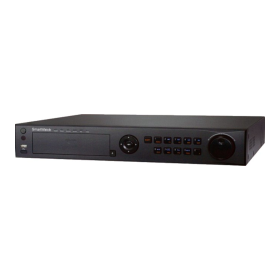
Page 12: Front Panel
SmartWatch DVR Operation Manual 1.1 Front Panel The front panel of the H20SWDVR4R, H20SWDVR8 & H20SWDVR16 are shown in Figure 1.1: Figure 1.1 Front panel of H20SWDVR4R, H20SWDVR8 & H20SWDVR16 Table 1.1 Description of H20SWDVR4R, H20SWDVR8 & H20SWDVR16 Front Panel Features... - Page 13 SmartWatch DVR Operation Manual control (with an address within 1~254) and keyboard at the same time and the SHIFT button is used as well; (b) when the DVR is controlled by an IR remote control (with an address within 1~254) and the SHIFT button is used.
- Page 14 SmartWatch DVR Operation Manual In PTZ control mode, the buttons can control the movement of the PTZ camera. Confirm selection in any of the menu modes. It can also be used to tick checkbox fields. In Playback mode, it can be used to play or pause the video.
-
Page 15: Ir Remote Control Operations
SmartWatch DVR Operation Manual 1.2 IR Remote Control Operations The device may also be controlled with the included IR remote control, shown in Figure 1.3. Batteries (2×AAA) must be installed before operation. Figure 1.3 Remote Control Table 1.3 Description of the IR Remote Control Buttons... - Page 16 SmartWatch DVR Operation Manual Name Description REC Button Entering the Manual Record settings menu. In PTZ control settings, press the REC button and then you can call a PTZ preset by pressing Numeric button. PLAY Button Entering the All-day Playback menu.
-
Page 17: Usb Mouse Operation
SmartWatch DVR Operation Manual 1.3 USB Mouse Operation A regular 3-button (Left/Right/Scroll-wheel) USB mouse can also be used with this device. To use a USB mouse: Plug USB mouse into one of the USB interfaces on the front panel of the device. -
Page 18: Rear Panel
SmartWatch DVR Operation Manual 1.5 Rear Panel The rear panels of the H20SWDVR4R, H20SWDVR8, H20SWDVR16 DVRs are shown in Figure 1.5, Figure 1.6 & Figure 1.7. Figure 1.5 Rear Panel of H20SWDVR4R Figure 1.6 Rear Panel of H20SWDVR8 Figure 1.7 Rear Panel of H20SWDVR16 Table 1.6 Description of H20SWDVR4R, H20SWDVR8 &... - Page 19 SmartWatch DVR Operation Manual and T- of PTZ receiver respectively. 12VDC power supply. POWER Switch for turning on/off the device. Ground (needs to be connected when DVR starts up). The rear panel of the H20SWDVR16R is shown in Figure 1.8 Figure 1.8 Rear Panel of H20SWDVR16R...
-
Page 20: Starting Up And Shutting Down The Device
SmartWatch DVR Operation Manual The rear panel of the H20SWDVR32R is shown in Figure 1.9 Figure 1.9 Rear Panel of H20SWDVR32R Table 1.8 Description of H20SWDVR32R Rear Panel Item Description BNC connectors for video output. VIDEO OUT AUDIO OUT RCA connector for audio output. - Page 21 SmartWatch DVR Operation Manual Menu > Shutdown Figure 1.10 Shutdown Menu Click the Shutdown button to enter the following dialog box: Figure 1.11 Dialog Box for Shutdown Click the Yes button. Turn off the power switch on the rear panel of DVR.
-
Page 22: Chapter 2
SmartWatch DVR Operation Manual CHAPTER 2 Getting Started... - Page 23 SmartWatch DVR Operation Manual The Setup Wizard can walk you through some important settings of the device. By default, the Setup Wizard starts once the device has loaded. Operating the Setup Wizard: Select the system language from the drop-down menu. The default resolution is 1280×1024/60Hz.
- Page 24 SmartWatch DVR Operation Manual Figure 2.3 Login Window Click the Next button to enter the Date and Time settings window, as shown in Figure 2.4. Set the time zone, date format, system date and system time. Figure 2.4 Date and Time Settings Click Next button which takes you back to the Network Setup Wizard window, as shown in Figure 2.5.
- Page 25 SmartWatch DVR Operation Manual Figure 2.5 Network Configuration The H20SWDVR4R, H20SWDVR8 & H20SWDVR16 models provide one 10M/100Mbps self-adaptive network interface, and the H20SWDVR16R & H20SWDVR32R models provide one 10M/100M/1000Mbps self-adaptive network interface. Click Next button to enter the HDD Management window, shown in Figure 2.6.
- Page 26 SmartWatch DVR Operation Manual Figure 2.7 Record Settings Click Copy to copy the record settings of the current camera to other camera (s) if needed, as shown in Figure 2.8. Figure 2.8 Copy Record Settings Click OK to return to the Record Settings window.
-
Page 27: Chapter 3
SmartWatch DVR Operation Manual CHAPTER 3 Live View... -
Page 28: Introduction Of Live View
SmartWatch DVR Operation Manual 3.1 Introduction of Live View Live view shows you the video image coming from each camera in real time. The device automatically enters Live View mode when powered on. It is also at the very top of the menu hierarchy, thus pressing the ESC many times (depending on which menu you’re on) brings you to the Live View mode. -
Page 29: Operations In Live View Mode
SmartWatch DVR Operation Manual 3.2 Operations in Live View Mode In live view mode, the following features are available: • Single Screen: shows only one screen on the monitor. • Multi-screen: shows multiple screens on the monitor simultaneously. • Auto-switch: the screen is auto switched from camera to camera. The dwell time must be set for each screen on the configuration menu before enabling auto-switch. -
Page 30: Using An Auxiliary Monitor
SmartWatch DVR Operation Manual Switch to multi-screen live view mode. Multi-screen The multi-screen icon varies according to the device models. Normal Record Start all-day normal recording for all channels. Motion Detection Start motion detection recording for all channels. Record Playback Play back recorded video. -
Page 31: Quick Setting Toolbar In Live View Mode
SmartWatch DVR Operation Manual switch to CVBS output as the main output. Steps: In the live view mode, use the mouse wheel to double-click on the HDMI/VGA output screen, and the following message box pops up: Figure 3.2 Main/Aux Monitor Switch Use the mouse wheel to double-click on the screen again to switch to the Aux output, or click Cancel to cancel the operation. - Page 32 SmartWatch DVR Operation Manual Digital Zoom Digital Zoom can zoom in on the selected area and make it full screen. You can left-click and draw to select the area for zooming in, as shown in Figure 3.4. Figure 3.4 Digital Zoom Image Settings Image Settings icon can be selected to enter the Image Settings menu.
- Page 33 SmartWatch DVR Operation Manual Adjust the image parameters including the brightness, contrast, saturation, hue, sharpness level and denoising level by moving the sliding bar or increasing/decreasing the value. The adjustable value range is 0~ 255 for the brightness, contrast, saturation and hue, 0~ 15 for the sharpness level and 0~5 for the denoising level.
-
Page 34: Adjusting Live View Settings
SmartWatch DVR Operation Manual 3.3 Adjusting Live View Settings Purpose: Live View settings can be customized according to different needs. You can configure the output interface, the dwell time for auto-switching, audio on/off etc. Steps: Enter the Live View Settings interface. - Page 35 SmartWatch DVR Operation Manual Figure 3.8 Live View- Camera Order To set the camera order: Click the View tab to enter the camera order settings interface. Select an output interface and select a screen layout. Click to select a screen in the right region and double-click to select a channel in the left region.
-
Page 36: Channel-Zero Encoding
SmartWatch DVR Operation Manual 3.4 Channel-zero Encoding Purpose: Channel-zero encoding decreases the bandwidth requirement without affecting image quality to enable remote real time viewing of multiple channels over a web browser / CMS (Client Management System) software. Steps: Enter the Live View Settings interface. -
Page 37: User Logout
SmartWatch DVR Operation Manual 3.5 User Logout Purpose: After logging out, the DVR will display live view mode. Steps: Enter the Shutdown menu. Menu>Shutdown Figure 3.10 Shutdown Click Logout. Once you have logged out of the system, menu operations will not be possible until you have... -
Page 38: Chapter 4
SmartWatch DVR Operation Manual CHAPTER 4 PTZ Controls... -
Page 39: Configuring Ptz Settings
SmartWatch DVR Operation Manual 4.1 Configuring PTZ Settings Purpose: Follow the procedure to set the parameters for PTZ. The configuring of the PTZ parameters should be carried out before you control the PTZ camera. Before you start: Check that the PTZ and the device are connected properly through the RS-485 interface. -
Page 40: Calling Presets
SmartWatch DVR Operation Manual Figure 4.2 PTZ- More Settings 2. Use the directional buttons to move the camera to the location where you want to set a preset. 3. Click the round icon before Save Preset. 4. Click the preset number to save the preset. -
Page 41: Customizing Patrols
SmartWatch DVR Operation Manual Figure 4.4 PTZ- Call Preset Choose the preset number. Call preset in live view mode: Steps: Click the PTZ Control icon in the quick setting bar to enter the PTZ setting menu in live view mode. - Page 42 SmartWatch DVR Operation Manual on to the next preset. The presets can be set following the steps above in Customizing Presets. Steps: Enter the PTZ Control interface. Menu>Camera>PTZ>More Settings Select patrol number. Select the under Patrol option box to add key points (presets) for the patrol.
-
Page 43: Calling Patrols
SmartWatch DVR Operation Manual Figure 4.8 KeyPoints Deletion 4.2.4 Calling Patrols Purpose: Calling a patrol makes the PTZ to move according to the predefined patrol path. Calling a patrol in the PTZ setting interface: Steps: In the PTZ setting interface. -
Page 44: Customizing Patterns
SmartWatch DVR Operation Manual Steps: 1. Press PTZ control on the IR remote, or click PTZ Control icon on the quick setting toolbar, to show the PTZ control toolbar. 2. Choose Patrol on the control bar. 3. Click the patrol you want to call. -
Page 45: Calling Patterns
SmartWatch DVR Operation Manual Figure 4.11 PTZ- Pattern 3. Click , and use your mouse to drag the image or click the eight directional buttons in the control box under the image to move the PTZ camera. The movement of the PTZ is recorded as the pattern. -
Page 46: Ptz Control Toolbar
SmartWatch DVR Operation Manual 3. Double click the pattern number you want to call, or you can select the pattern number and click call the pattern. Figure 4.13 PTZ Toolbar- Pattern 4.3 PTZ Control Toolbar In the Live View mode, you can press the PTZ Control button on the IR remote control, or choose the PTZ Control icon to enter the PTZ toolbar. - Page 47 SmartWatch DVR Operation Manual The speed of the PTZ Light on/off Wiper on/off movement Image 3D-Zoom Preset Centralization Patrol Pattern Menu Start Previous item Next item pattern/patrol Stop the patrol Minimize or pattern Exit windows movement...
-
Page 48: Chapter 5
SmartWatch DVR Operation Manual CHAPTER 5 Record Settings... -
Page 49: Configuring Encoding Parameters
SmartWatch DVR Operation Manual 5.1 Configuring Encoding Parameters Purpose: By configuring the encoding parameters you can define the transmission stream type, the resolution and so on. Before you start: 1. Make sure that the HDD has already been installed. If not, please install a HDD and initialize it. - Page 50 SmartWatch DVR Operation Manual Select the camera for configuration. Configure the following parameters for the Main Stream (Normal) and the Main Stream (Event): • Stream Type: Set the stream type to be Video or Video & Audio. • Resolution: Set recording at resolution of WD1 (960H), 4CIF, 2CIF, CIF or QCIF.
-
Page 51: Configuring Record Schedule
SmartWatch DVR Operation Manual You can click the Restore button to restore the current main stream settings to the default parameters. Set encoding parameters for sub-stream Click the Substream tab to enter the Substream settings interface. Figure 5.5 Encoding Parameters-Sub-stream Configure the parameters for the sub-stream. - Page 52 SmartWatch DVR Operation Manual Figure 5.6 Record Schedule Choose the camera you want to configure. Check the check box after the Enable Schedule item. There are two ways to configure the record schedule. Task 1: Edit the Schedule Steps: Click Edit.
- Page 53 SmartWatch DVR Operation Manual other days, click Copy. Figure 5.8 Copy Schedule to Other Days The Holiday option is available in the Schedule dropdown list when you have enabled holiday schedule in Holiday Settings. Refer to Chapter 5.5 Configuring Holiday Record.
- Page 54 SmartWatch DVR Operation Manual Figure 5. 10 Draw the Schedule 3) You can repeat the above steps to set a schedule for other channels. Click Copy to enter the Copy Camera interface and then choose the channels to which you want to copy.
-
Page 55: Configuring Motion Detection Record
SmartWatch DVR Operation Manual 5.3 Configuring Motion Detection Record Purpose: Follow the steps to set the motion detection parameters. In the live view mode, once a motion detection event takes place, the device can analyze it and perform actions as a response. Enabling motion detection function can trigger certain channels to start recording, or trigger full screen monitoring, audio warning, notify the surveillance center and so on. - Page 56 SmartWatch DVR Operation Manual Figure 5.14 Motion Detection Handling 5) Select the channels which you want the motion detection event to trigger recording on. 6) Click Apply to save the settings. 7) Click OK to return to the upper level menu.
- Page 57 SmartWatch DVR Operation Manual 4) Set the Type as Motion. 5) To schedule an all-day recording, check the checkbox after the All Day item. Figure 5.17 Edit Schedule- All Day 6) To arrange another schedule, leave the All Day checkbox blank and set the Start/End time.
-
Page 58: Configuring Alarm Triggered Record
SmartWatch DVR Operation Manual 5.4 Configuring Alarm Triggered Record Purpose: Follow the procedure to configure alarm triggered recording or capture. Steps: Enter the Alarm setting interface. Menu> Configuration> Alarm Figure 5.20 Alarm Settings Click Alarm Input tab. Figure 5.21 Alarm Settings- Alarm Input Select Alarm Input No. -
Page 59: Configuring Manual Record
SmartWatch DVR Operation Manual Choose the alarm triggered recording/capture channel. Check the checkbox to select channel. Click Apply to save settings. Click OK to return to the upper level menu. Click Apply in the Alarm Input interface to save the settings. -
Page 60: Configuring Holiday Record
SmartWatch DVR Operation Manual Steps: Enter the Manual settings interface. Menu> Manual Figure 5.25 Manual Record Enable recording for camera (s). Click the status button beside each camera number to change , or you can enable recording for all cameras by clicking the status button before Analog to change it to Set recording mode to manual. - Page 61 SmartWatch DVR Operation Manual Choose Holiday on the left bar. Figure 5.27 Holiday Settings Click to enter the Edit interface Figure 5.28 Edit Holiday Settings 1) Check the checkbox after Enable. 2) Select Mode from the dropdown list. There are three different modes for the date format to configure holiday schedule.
- Page 62 SmartWatch DVR Operation Manual Figure 5.29 Edit Schedule- Holiday 5) Select Motion or Normal from the Type dropdown list. 6) If you need all day recording, check the All Day checkbox. Otherwise leave it blank. 7) Set start/end time for holiday schedule.
-
Page 63: Configuring Redundant Record
SmartWatch DVR Operation Manual 5.7 Configuring Redundant Record Purpose: Enabling redundant recording will save the recorded files not only in the R/W (read/write) HDD but also in the redundant HDD, and will effectively enhance data safety and reliability. You must set the Storage mode in the HDD advanced settings to Group before you set the HDD property to Redundant. -
Page 64: Configuring Hdd Group For Record
SmartWatch DVR Operation Manual Figure 5.32 Encoding Record 2) Select Camera you want to configure. 3) Check the checkbox of the Redundant Record. 4) Click Apply to save settings and return to the upper level menu. Repeat the above steps (2-4) for configuring other channels. - Page 65 SmartWatch DVR Operation Manual Figure 5.34 HDD-Advanced 2) Choose Group number in the dropdown list of Record on HDD Group. 3) Check the channels you want to save in this group. 4) Click Apply to save settings. After having configured the HDD groups, you can configure the Recording settings following...
-
Page 66: Files Protection
SmartWatch DVR Operation Manual 5.9 Files Protection Purpose: You can lock the recorded files or set the HDD property to Read-only to protect the recorded files from being overwritten. Protect file by locking the recorded files: Steps: Enter Playback setting interface. - Page 67 SmartWatch DVR Operation Manual Click to change it to to unlock the file so that it is not protected. Figure 5.37 Unlocking Attention Protect file by setting HDD property to Read-only To edit this HDD property, you need to set the storage mode of the HDD to Group. See Chapter 10.4 Managing HDD Group.
- Page 68 SmartWatch DVR Operation Manual If there is only one HDD and it is set to Read-only, the device won’t be able to record any files. Only live view mode will be available. If you set the HDD to Read-only when the device is writing files to it, the file will be saved in the next...
-
Page 69: Chapter 6
SmartWatch DVR Operation Manual CHAPTER 6 Playback... -
Page 70: Playing Back Recorded Files
SmartWatch DVR Operation Manual 6.1 Playing Back Recorded Files 6.1.1 Playing Back by Channel Purpose: Play back the recorded video files of a specific channel in the live view mode. Channel switch is supported. Instant playback by channel: Steps: Choose a channel in live view mode using the mouse and click the button in the quick setting toolbar. - Page 71 SmartWatch DVR Operation Manual Pressing numerical buttons will switch playback to the corresponding channels during the playback process. Playback management. The toolbar in the bottom part of the Playback interface can be used to control playing progress, as shown in Figure 6.3.
-
Page 72: Playing Back By Time
SmartWatch DVR Operation Manual : There is recorded file(s) in this day (not current day). : There is only event recorded file(s) in this day (not current day). : Mouse cursor is located above date. Figure 6.5 Toolbar of All-day Playback Table 6.1 Detailed Explanation of All-day-playback Toolbar... - Page 73 SmartWatch DVR Operation Manual Figure 6.6 Record Information Click Back to return to the playback interface. Set search conditions and click the Playback button to enter the Playback interface. Figure 6.7 Video Search by Time In the Playback interface: The toolbar on the bottom part of Playback interface can be used to control playback, as shown in Figure 6.9.
-
Page 74: Playing Back By Normal Video Search
SmartWatch DVR Operation Manual Figure 6.9 Toolbar of Playback by Time Table 6.2 Detailed Explanation of Playback-by-time Toolbar Button Operation Button Operation Button Operation Button Operation Audio Start/Stop clipping 30s forward on/Mute reverse Add default Add customized Speed management down... - Page 75 SmartWatch DVR Operation Manual Figure 6.10 Normal Video Search Choose a recorded file to play back. If there is only one channel in the search results, clicking button takes you to Full-screen Playback interface of this channel. If there is more than one channel in the search results, clicking button takes you to step 3 and step Figure 6.11 Result of Normal Video Search...
- Page 76 SmartWatch DVR Operation Manual Figure 6. 13 4-ch Synchronous Playback Interface The hidden list of recorded files appears by moving the mouse to the right of the playback interface. Figure 6. 14 4-ch Synchronous Playback Interface with Video List Figure 6. 15 Toolbar of Normal Playback Table 6.3 Detailed Explanation of Normal Playback Toolbar...
-
Page 77: Playing Back By Event Search
SmartWatch DVR Operation Manual play/Reverse play/Play/Single- play/ Single- frame play frame reverse play Video Previous file Next file Exit search Video type Hide toolbar Progress bar 1. Playback progress bar: use the mouse to click any point of the progress bar or drag the progress bar to locate special frames. - Page 78 SmartWatch DVR Operation Manual Figure 6.17 Video Search by Motion Detection Select the camera (s) for searching of motion detection triggered recorded files or select the alarm input (s) for the alarm triggered record files. Click Search button to enter the Search Result interface.
- Page 79 SmartWatch DVR Operation Manual Figure 6.19 Event Details Or you can directly click the button of each file item to enter its playback interface. The toolbar in the bottom part of Playback interface can be used to control playback. Figure 6.20 Interface of Playback by Event (1)
- Page 80 SmartWatch DVR Operation Manual Figure 6.21 Interface of Playback by Event (2) Figure 6.22 Toolbar of Playback by Event Table 6.4 Detailed Explanation of Playback-by-event Toolbar Button Operation Button Operation Button Operation Button Operation Start/Stop Audio on/Mute 30s forward clipping...
-
Page 81: Playing Back By Tag
SmartWatch DVR Operation Manual 2. Video type bar colourings: represents normal recording (manual or schedule); represents event recording; represents smart search recording. 6.1.5 Playing Back by Tag Purpose: Video tag allows you to add information to a defined period of time during playback e.g. event name, person name etc. - Page 82 SmartWatch DVR Operation Manual Figure 6.24 Tag Management Interface Steps: Enter Playback interface. Menu>Playback Click Tag tab to enter Playback by Tag interface. Choose channels, tag type and time, and click Search to enter Search Result interface. Two tag types are selectable: All and Tag Keyword. Input keyword if you choose Tag Keyword.
- Page 83 SmartWatch DVR Operation Manual Figure 6.26 Result of Video Search by Tag Playback by tag. Choose a tag and click button to play back the related recorded file. Figure 6.27 Interface of Playback by Tag The hidden list of tags will appear by moving the mouse to the right of the playback interface.
- Page 84 SmartWatch DVR Operation Manual Figure 6.28 Interface of Playback by Tag with Video List Figure 6.29 Toolbar of Playback by Tag Table 6.5 Detailed Explanation of Playback-by-tag Toolbar Button Operation Button Operation Button Operation Button Operation Audio Start/Stop clipping 30s forward...
-
Page 85: Playing Back By System Log
SmartWatch DVR Operation Manual Video type bar colourings: represents normal recording (manual or schedule); represents event recording; represents smart search recording. 6.1.6 Playing Back by System Log Purpose: Play back recorded file(s) associated with channels after searching system logs. Steps: Enter Log Search interface. - Page 86 SmartWatch DVR Operation Manual If there is no recorded file at the time point of the log, the message box “No result found” will pop The toolbar in the bottom part of Playback interface can be used to control playback.
-
Page 87: Auxiliary Functions Of Playback
SmartWatch DVR Operation Manual 6.2 Auxiliary Functions of Playback 6.2.1 Playing Back Frame by Frame Purpose: Play video files frame by frame for close analysis. Steps: • Using a Mouse: Go to the Playback interface. Click button until the speed changes to Single frames and one click on the playback screen represents playback of one frame. - Page 88 SmartWatch DVR Operation Manual Figure 6.33 Playback Interface Right-click on the mouse and select Smart Search to draw and select the required target search area. Figure 6.34 Right-click Menu in All-day Playback and Normal Playback Interface 3. You can click button to set the full screen as the target search area.
- Page 89 SmartWatch DVR Operation Manual Figure 6.35 Draw Area of Smart Search Different video type bars are marked in different colors: : Normal record file; : Event record file; : Smart search record file. The hidden list of recorded files appears by moving the mouse to the right of the playback interface.
-
Page 90: Digital Zoom
SmartWatch DVR Operation Manual Figure 6.37 Toolbar of Smart Search Playback Table 6.6 Detailed Explanation of Smart-search-playback Toolbar Button Operation Button Operation Button Operation Button Operation Start/Stop Audio on/Mute 30s forward clipping reverse Add default Add customized Slow management down... - Page 91 SmartWatch DVR Operation Manual Figure 6.38 Draw Area for Digital Zoom Figure 6.39 Right-click Menu in Playback Mode Right-click menu: This menu differs slightly from one playback interface to another. Table 6.7 Detailed Explanation of Right-click Menu under Playback Button...
-
Page 92: Chapter 7
SmartWatch DVR Operation Manual CHAPTER 7 Backup... -
Page 93: Backing Up Recorded Files
SmartWatch DVR Operation Manual 7.1 Backing up Recorded Files Before you start: Please insert the backup device(s) into the device. 7.1.2 Backing up by Normal Video Search Purpose: The recorded files can be backed up to USB devices (USB flash drives, USB HDDs, USB writer) and DVDs on models which include a DVD-R drive. - Page 94 SmartWatch DVR Operation Manual Figure 7.2 Result of Normal Video Search for Backup Export the recorded files. Click the Export button to start backup. If the inserted device is not recognized: • Click the Refresh button. • Reconnect device. •...
- Page 95 SmartWatch DVR Operation Manual Figure 7. 4 Export by Normal Video Search using USB Writer Stay in the Exporting interface until all recorded files are exported and a window pops up saying “Export finished”. Figure 7.5 Export Finished Check backup result.
-
Page 96: Backing Up By Event Search
SmartWatch DVR Operation Manual Figure 7.6 Checkup of Export Result using USB Flash Drive Figure 7. 7 Checkup of Export Result using USB Writer 7.1.3 Backing up by Event Search Purpose: Back up event-related recorded files using USB devices (USB flash drives, USB HDDs, USB writer) and DVDs on models which include a DVD-R drive. - Page 97 SmartWatch DVR Operation Manual The following steps show how to backup recorded files triggered by motion detection. The same procedure applies to recorded files triggered by alarm inputs. Set the start time and end time in which you want to search.
- Page 98 SmartWatch DVR Operation Manual Figure 7.10 Event Details Interface Export the selected recorded files. Click the Export button and start backing up. If the inserted USB device is not recognized: • Click the Refresh button. • Reconnect device. • Check compatibility of the device with your dealer.
-
Page 99: Backing Up Video Clips
SmartWatch DVR Operation Manual “Export finished”. Figure 7.12 Export Finished Check backup result. Choose the recorded file in Export interface and click button to check it. The Player player.exe will be exported automatically to your backup device during file export. - Page 100 SmartWatch DVR Operation Manual Exit the Playback interface after finishing clipping and you will then be prompted to save the clips. A maximum of 30 clips can be selected for each channel. Figure 7.14 Interface of Playback by Time Click Yes to save video clips and enter the Export interface, or click No to quit and do not save the video clips.
- Page 101 SmartWatch DVR Operation Manual Figure 7.16 Export Video Clips Using USB Flash Drive Stay in the Exporting interface until all recorded files are exported and a window pops up saying “Export finished”. Figure 7.17 Export Finished Check backup result. The Player player.exe will be exported automatically to your backup device during file export.
-
Page 102: Managing Backup Devices
SmartWatch DVR Operation Manual Figure 7.18 Checkup of Video Clips Export Result Using USB Flash Drive 7.2 Managing Backup Devices Management of USB flash drive, USB HDD and eSATA HDD. The eSATA HDD is supported by H20SWDVR16R & H20SWDVR32R models only. - Page 103 SmartWatch DVR Operation Manual Figure 7.20 Result of Normal Video Search for Backup Backup device management. Click New Folder button if you want to create a new folder in the backup device. Select a recorded file or folder in the backup device and click button if you want to delete it.
- Page 104 SmartWatch DVR Operation Manual Management of USB writers and DVD-R/W Enter Search Result interface of recorded files. Menu>Export>Normal Set search condition and click the Search button to enter the Search Results interface. At least one channel must be selected. Figure 7.22 Normal Video Search for Backup Select recorded files you want to back up.
- Page 105 SmartWatch DVR Operation Manual • Click the Refresh button. • Reconnect device. • Check device compatibility with your dealer. Figure 7.24 USB Writer Management...
-
Page 106: Chapter 8
SmartWatch DVR Operation Manual CHAPTER 8 Alarm Settings... -
Page 107: Setting Motion Detection
SmartWatch DVR Operation Manual 8.1 Setting Motion Detection Steps: Enter Motion Detection interface and choose a camera you want to set motion detection up on. Menu> Camera> Motion Figure 8.1 Motion Detection Setup Interface Set motion detection area and sensitivity. - Page 108 SmartWatch DVR Operation Manual Set up arming schedule of the channel. Select Arming Schedule tab to set the channel’s arming schedule. Up to 8 time periods can be set up for each day of the week. Click Apply to save the arming settings for the selected day.
-
Page 109: Setting Sensor Alarms
SmartWatch DVR Operation Manual It is not possible to copy the “Trigger Channel” action. Figure 8.6 Copy Settings of Motion Detection 8.2 Setting Sensor Alarms Purpose: Configure response to sensor alarms. Steps: Enter Alarm Settings interface and select an alarm input. - Page 110 SmartWatch DVR Operation Manual Figure 8.8 Alarm Input Settings Interface 3. Click Trigger Channel tab and select one or more channels which will start to record or enter full-screen mode when an external alarm is triggered. Click Apply to save the settings.
- Page 111 SmartWatch DVR Operation Manual Figure 8.10 Set PTZ Linking of Alarm Input 7. If you want to configure another alarm input, repeat the above steps or just copy the above settings to the new input by clicking Copy in the Alarm Input Settings interface.
-
Page 112: Detecting Video Loss
SmartWatch DVR Operation Manual 8.3 Detecting Video Loss Purpose: Detect video loss on a channel and take alarm response action(s). Steps: Enter Video Loss interface of Camera Management. Menu> Camera> Video Loss Figure 8.12 Video Loss Setup Interface Select a channel on which you want to detect video loss. -
Page 113: Detecting Video Tampering
SmartWatch DVR Operation Manual 8.4 Detecting Video Tampering Purpose: Trigger alarm when the lens is covered and take alarm response action(s). Steps: 1. Enter Video Tampering interface of Camera Management. Menu> Camera> Video Tampering Detection Figure 8.14 Video Tampering Detection Setup Interface 2. -
Page 114: Handling Exceptions
SmartWatch DVR Operation Manual 8.5 Handling Exceptions Purpose: Exception settings refer to the handling method of various exceptions, e.g., • HDD Full: The HDD is full. • HDD Error: Writing HDD error, unformatted HDD, etc. • Network Disconnected: Disconnected network cable. -
Page 115: Setting Alarm Response Actions
SmartWatch DVR Operation Manual 8.6 Setting Alarm Response Actions Purpose: The alarm response actions will be activated when an exception occurs, including Full Screen Monitoring, Audible Warning, Notify Surveillance Center, and Send Email. Full Screen Monitoring When an alarm event (motion detection/video tampering detection/video loss detection) is triggered, the local monitor (HDMI/VGA or BNC monitor) will display the video image from the alarming channel in full screen. - Page 116 SmartWatch DVR Operation Manual Figure 8.17 Alarm Output Settings Interface Set arming schedule of the alarm output. Click to set the arming schedule of alarm output. Up to 8 time periods can be set for each day of the week.
- Page 117 SmartWatch DVR Operation Manual Figure 8.19 Copy Settings of Alarm Output...
-
Page 118: Triggering Or Clearing Alarm Output Manually
SmartWatch DVR Operation Manual 8.7 Triggering or Clearing Alarm Output Manually Purpose: Sensor alarms can be triggered or cleared manually. If Manually Clear is selected in the dropdown list of dwell time of an alarm output, the alarm can be cleared only by clicking Clear button in the following interface. -
Page 119: Chapter 9
SmartWatch DVR Operation Manual CHAPTER 9 Network Settings... -
Page 120: Configuring General Settings
Network settings must be properly configured before you can operate the device over a network. Steps: Enter the Network Settings interface. Menu > Configuration > Network Figure 9.1 General Network Settings of H20SWDVR4R, H20SWDVR16 & H20SWDVR32 Figure 9.2 General Network Settings of H20SWDVR16R & H20SWDVR32R Select the General tab. In the General Settings interface: You can configure the following settings: NIC Type, IPv4 Address, IPv4 Gateway, MTU and DNS Server. -
Page 121: Configuring Advanced Settings
SmartWatch DVR Operation Manual The valid value range of MTU is 500 ~ 1500. After having configured the general settings, click the Apply button to save the settings. 9.2 Configuring Advanced Settings 9.2.1 Configuring PPPoE Settings Purpose: Your device also allows access by Point-to-Point Protocol over Ethernet (PPPoE). - Page 122 SmartWatch DVR Operation Manual Enter the Network Settings interface. Menu > Configuration > Network Select the DDNS tab to enter the DDNS Settings interface. Figure 9.5 DDNS Settings Interface Check the DDNS checkbox to enable this feature. Select DDNS Type. Five different DDNS types are selectable: IPServer, DynDNS, PeanutHull, NO- IP and hkDDNS.
- Page 123 SmartWatch DVR Operation Manual Figure 9.8 Peanut Hull Settings Interface • NO-IP: Enter the account information in the corresponding fields. Refer to the DynDNS settings. 1) Enter Server Address for NO-IP. 2) In the Device Domain Name text field, enter the domain obtained from the NO-IP website (www.no-ip.com).
-
Page 124: Configuring Ntp Server
SmartWatch DVR Operation Manual Figure 9.11 Register an Account In the DDNS Management System interface, click the Device Management tab on the left menu bar and then click to register the device. Figure 9.12 Register the Device Only lower-case English alphabet, numeric and ‘-’ can be used in the alias of the device and the alias must be started with letters of the lower-case English alphabet. -
Page 125: Configuring Snmp
SmartWatch DVR Operation Manual Check the Enable NTP checkbox to enable this feature. Configure the following NTP settings: • Interval: Time interval between the two synchronizing actions with NTP server. The unit is measured in minutes. • NTP Server: IP address of NTP server. -
Page 126: Configuring Upnp
SmartWatch DVR Operation Manual information via SNMP port. By setting the Trap Address, the device is allowed to send the alarm event and exception message to the surveillance center. 9.2.5 Configuring UPnP™ Purpose: UPnP™ permits the device to seamlessly discover the presence of other network devices on the network and establish functional network services for data sharing, communications, etc. -
Page 127: Configuring Remote Alarm Host
The Alarm Host IP refers to the IP address of the remote PC on which the CMS (Client Management System) software (e.g. SmartWatch System Manager) is installed, and the Alarm Host Port must be the same as the alarm monitoring port configured in the software (default port is 7200). -
Page 128: Configuring Multicast
SmartWatch DVR Operation Manual Figure 9.20 Configure Alarm Host Click the Apply button to save and exit the interface. 9.2.7 Configuring Multicast Purpose: A multicast address spans the Class-D IP range of 224.0.0.0 to 239.255.255.255. It is recommended to use the IP address ranging from 239.252.0.0 to 239.255.255.255. -
Page 129: Configuring Server And Http Ports
SmartWatch DVR Operation Manual Figure 9.22 RTSP Settings Interface Enter the RTSP port in the text field of RTSP Service Port. The default RTSP port is 554, and you can change it according to different requirements. Click the Apply button to save and exit the menu. - Page 130 SmartWatch DVR Operation Manual maintains an SMTP mail server. The network must also be connected to either an intranet or the Internet depending on the location of the e-mail accounts to which you want to send notification. Steps: Enter the Network Settings interface.
- Page 131 SmartWatch DVR Operation Manual Select Receivers: Select the receiver. Up to 3 receivers can be configured. Receiver: The name of user to be notified. Receiver’s Address: The Email address of user to be notified. Enable Attached Pictures: Check the checkbox of Enable Attached Picture if you want to send email with attached alarm images.
-
Page 132: Checking Network Traffic
SmartWatch DVR Operation Manual 9.3 Checking Network Traffic Purpose: You can check the network traffic to obtain real-time information on the device such as linking status, MTU, sending/receiving rate, etc. Steps: Enter the Network Traffic interface. Menu > Maintenance > Net Detect Figure 9.28 Network Traffic Interface... -
Page 133: Network Detection
SmartWatch DVR Operation Manual 9.4 Network Detection Purpose: You can obtain network connection status of device through the network detection function, including network delay, packet loss, etc. 9.4.1 Testing Network Delay and Packet Loss Steps: Enter the Network Traffic interface. -
Page 134: Checking Network Status
SmartWatch DVR Operation Manual fails to detect the backup device, please check whether it is compatible with the device. You can format the backup device if the format is incorrect. Figure 9.31 Export Network Packet Click the Export button to start exporting. - Page 135 SmartWatch DVR Operation Manual Figure 9.33 Checking Network Status If the network is normal the following message box pops up. Figure 9.34 Network Status Checking Result If the message box pops up with different information, you can click Network button to show the interface for quick setting of network parameters.
-
Page 136: Checking Network Statistics
SmartWatch DVR Operation Manual 9.4.4 Checking Network Statistics Purpose: You can check the network statistics to obtain real-time information on the device. Steps: Enter the Network Statistics interface. Menu > Maintenance> Net Detect Click the Network Stat. tab to enter the Network Statistics menu. -
Page 137: Chapter 1 0
SmartWatch DVR Operation Manual CHAPTER 10 HDD Management... -
Page 138: Initializing Hdds
SmartWatch DVR Operation Manual 10.1 Initializing HDDs Purpose: A newly installed hard disk drive (HDD) must be initialized before it can be used with your device. Steps: Enter the HDD Information interface. Menu > HDD>General Figure 10.1 HDD Information Interface Select the HDD to be initialized. - Page 139 SmartWatch DVR Operation Manual Figure 10. 3 Start Initialization After the HDD has been initialized, the status of the HDD will change from Uninitialized to Normal. Figure 10.4 HDD Status Changes to Normal Initializing the HDD will erase all data on it.
-
Page 140: Managing Network Hdd
SmartWatch DVR Operation Manual 10.2 Managing Network HDD Purpose: You can add a NAS or disk of IP SAN to the device, and use it as a network HDD. Steps: Enter the HDD Information interface. Menu > HDD > General Figure 10.5 HDD Information Interface... - Page 141 SmartWatch DVR Operation Manual Configure the NAS or IP SAN settings. • Add NAS disk: 1) Enter the NetHDD IP address in the text field. 2) Enter the NetHDD Directory in the text field. 3) Click the OK button to add the configured NAS disk.
- Page 142 SmartWatch DVR Operation Manual After having successfully added the NAS or IP SAN disk, return to the HDD Information menu. The added NetHDD will be displayed in the list. If the added NetHDD is uninitialized, please select it and click the Init button for initialization.
-
Page 143: Managing Hdd Group
SmartWatch DVR Operation Manual 10.3 Managing HDD Group 10.3.1 Setting HDD Groups Purpose: Multiple HDDs can be managed in groups. Video from specified channels can be recorded onto a particular HDD group through HDD settings. Steps: Enter the Storage Mode interface. -
Page 144: Setting Hdd Property
SmartWatch DVR Operation Manual Figure 10.12 Local HDD Settings Interface Select the Group number for the current HDD. The default group No. for each HDD is 1. Click the OK button to confirm the settings. Figure 10. 13 Confirm HDD Group Settings In the pop-up Attention box, click the Yes button to finish the settings. - Page 145 SmartWatch DVR Operation Manual Figure 10.14 Set HDD Property Set the HDD property to R/W, Read-only or Redundancy. Click the OK button to save the settings and exit the interface. In the HDD Information menu, the HDD property will be displayed in the list.
-
Page 146: Configuring Quota Mode
SmartWatch DVR Operation Manual 10.4 Configuring Quota Mode Purpose Each camera can be configured with an allocated quota for the storage of recorded files. Steps Enter the Storage Mode interface. Menu > HDD > Advanced Set the Mode to Quota. -
Page 147: Checking Hdd Status
SmartWatch DVR Operation Manual 10.5 Checking HDD Status Purpose: You can check the status of the installed HDDs. Checking HDD Status in HDD Information Interface Steps: Enter the HDD Information interface. Menu > HDD>General Check the status of each HDD which is displayed on the list. -
Page 148: Checking S.m.a.r.t. Information
SmartWatch DVR Operation Manual 10.6 Checking S.M.A.R.T. Information Purpose: The S.M.A.R.T. (Self-Monitoring, Analysis and Reporting Technology) is a monitoring system for HDDs to detect and report on various indicators of reliability in the hope of anticipating failures. Steps: Enter the S.M.A.R.T. Settings interface. -
Page 149: Detecting Bad Sector
SmartWatch DVR Operation Manual 10.7 Detecting Bad Sector Purpose: The bad sectors of a HDD may cause the system to slow down when reading or writing data. You can detect the bad sectors of the HDD using this tool. Steps: Enter the Bad Sector Detection interface. -
Page 150: Configuring Hdd Error Alarms
SmartWatch DVR Operation Manual 10.8 Configuring HDD Error Alarms Purpose: You can configure HDD error alarms when the HDD status is Uninitialized or Abnormal. Steps: Enter the Exception interface. Menu > Configuration > Exceptions Set the Exception Type to HDD Error from the dropdown list. -
Page 151: Chapter 11
SmartWatch DVR Operation Manual CHAPTER 11 Camera Settings... -
Page 152: Configuring Osd Settings
SmartWatch DVR Operation Manual 11.1 Configuring OSD Settings Purpose: You can configure the OSD (On-screen Display) settings for cameras, including date /time, camera name, etc. Steps: Enter the OSD Configuration interface. Menu > Camera > OSD Select the camera to configure OSD settings. -
Page 153: Configuring Privacy Mask
SmartWatch DVR Operation Manual 11.2 Configuring Privacy Mask Purpose: Up to 4 four-sided privacy mask zones can be configured. Steps: Enter the Privacy Mask Settings interface. Menu > Camera > Privacy Mask Select the camera to set privacy mask. Click the checkbox of Enable Privacy Mask to enable this feature. -
Page 154: Configuring Video Parameters
SmartWatch DVR Operation Manual Please refer to step 7 of Chapter 11.1 Configuring OSD Settings. Click the Apply button to save the settings. You can also click the Restore button to restore the current OSD settings to the default parameters. -
Page 155: Chapter 1 2
SmartWatch DVR Operation Manual CHAPTER 12 Device Management and Maintenance... -
Page 156: Viewing System Information
SmartWatch DVR Operation Manual 12.1 Viewing System Information 12.1.1 Viewing Device Information Steps: Enter the System Information interface. Menu > Maintenance > System Info Click the Device Info tab to enter the Device Information menu to view the device name, model, serial No. -
Page 157: Viewing Alarm Information
SmartWatch DVR Operation Manual Steps: Enter the System Information interface. Menu > Maintenance > System Info Click the Record tab to enter the Record Information menu to view the recording status and encoding parameters of each camera. Figure 12.3 Record Information Interface 12.1.4 Viewing Alarm Information... -
Page 158: Viewing Network Information
SmartWatch DVR Operation Manual 12.1.5 Viewing Network Information Steps: Enter the System Information interface. Menu > Maintenance > System Info Click the Network tab to enter the Network Information menu to view the network information. Figure 12.5 Network Information Interface 12.1.6 Viewing HDD Information... -
Page 159: Searching & Exporting Log Files
SmartWatch DVR Operation Manual 12.2 Searching & Exporting Log Files Purpose: The operation, alarm, exception and information of the device can be stored in log files, which can be viewed and exported at any time. Steps: Enter the Log Search interface. - Page 160 SmartWatch DVR Operation Manual Figure 12.8 Log Search Results 5. You can click the button of each log or double click it to view its detailed information. And you can also click the button to view the related video files if available.
-
Page 161: Importing/Exporting Configuration Files
SmartWatch DVR Operation Manual Figure 12.10 Log Export Interface Check checkbox to select the HDD and click Export to enter the export interface. Figure 12.11 Export Log Files Select the backup device from the dropdown list of Device Name. Click the Export to export the log files to the selected backup device. - Page 162 SmartWatch DVR Operation Manual Figure 12.12 Import/Export Config File Click the Export button to export configuration files to the selected local backup device. To import a configuration file, select the file from the selected backup device and click the Import button.
-
Page 163: Upgrading System
SmartWatch DVR Operation Manual 12.4 Upgrading System Purpose: The firmware on your device can be upgraded using a USB device or remote FTP server. 12.4.1 Upgrading by USB Device Steps: Connect the USB device where the updated firmware file is located to the DVR. - Page 164 SmartWatch DVR Operation Manual Figure 12.14 FTP Upgrade Interface Enter the FTP Server Address in the text field. Click the Upgrade button to start upgrading. After the upgrading is complete, reboot the device to activate the new firmware.
-
Page 165: Restoring Default Settings
SmartWatch DVR Operation Manual 12.5 Restoring Default Settings Steps: Enter the Default interface. Menu > Maintenance > Default Figure 12.15 Restore Factory Default Click the OK button to restore the default settings. With the exception of the network parameters (including IP address, subnet mask, gateway, MTU and... -
Page 166: Chapter 1 3
SmartWatch DVR Operation Manual CHAPTER 13 Others... -
Page 167: Configuring General Settings
SmartWatch DVR Operation Manual 13.1 Configuring General Settings Purpose: You can configure the BNC output standard, VGA/HDMI output resolution, mouse pointer speed, etc. Steps: Enter the General Settings interface. Menu > Configuration > General Select the General tab. Figure 13.1 General Settings Interface Configure the following settings: •... - Page 168 SmartWatch DVR Operation Manual • Transparent Channel: Connect a serial device directly to the device. The serial device will be controlled remotely by the PC through the network. Steps: Enter the RS-232 Settings interface. Menu > Configuration > RS-232 Figure 13.2 RS-232 Settings Interface Configure RS-232 parameters, including baud rate, data bit, stop bit, parity, flow control and usage.
-
Page 169: Configuring Dst Settings
SmartWatch DVR Operation Manual 13.3 Configuring DST Settings Steps: Enter the General Settings interface. Menu >Configuration>General Choose DST Settings tab. Figure 13.3 DST Settings Interface You can check the checkbox before the Auto DST Adjustment item. Or you can manually check the Enable DST checkbox, and then set the date of the DST period. -
Page 170: Configuring More Settings
SmartWatch DVR Operation Manual 13.4 Configuring More Settings Steps: Enter the General Settings interface. Menu > Configuration > General Click the More Settings tab to enter the More Settings interface. Figure 13.4 More Settings Interface Configure the following settings: •... -
Page 171: Managing User Accounts
SmartWatch DVR Operation Manual 13.5 Managing User Accounts Purpose: There is a default account in the device: Administrator. The default Administrator user name is admin and the default password is 12345. The Administrator has the permission to add and delete users and configure user parameters. - Page 172 SmartWatch DVR Operation Manual • Operator: The Operator user level has permission to carry out Local Log Search in Local Configuration, Remote Log Search and Two-way Audio in Remote Configuration and all operating permissions in Camera Configuration. • Guest: The Guest user has permission to carry out Local Log Search in Local Configuration, Remote Log Search in Remote Configuration and only has the local/remote playback in the Camera Configuration.
-
Page 173: Deleting A User
SmartWatch DVR Operation Manual • Local Advanced Operation: Operating HDD management (initializing HDD, setting HDD property), upgrading system firmware, clearing I/O alarm output. • Local Shutdown /Reboot: Shutting down or rebooting the device. Remote Configuration • Remote Log Search: Remotely viewing logs that are saved on the device. -
Page 174: Editing A User
SmartWatch DVR Operation Manual Figure 13.9 Delete a User Click the icon to delete the selected user. 13.5.3 Editing a User Steps: Enter the User Management interface. Menu > Configuration > User Select the user to be edited from the list. -
Page 175: Changing Password Of Admin
SmartWatch DVR Operation Manual Figure 13.11 Edit User Interface Edit the user information, including user name, password, level and MAC address. Click the OK button to save the settings and exit the menu. 13.5.4 Changing Password of Admin Purpose: The password for the admin user account can be changed in the User Management menu. - Page 176 SmartWatch DVR Operation Manual Figure 13.13 Change Password Enter the old password, check checkbox, enter new password and confirm password on the menu. Click to save the settings and exit the menu.
-
Page 177: Logging Out/Shutting Down/Rebooting Device
SmartWatch DVR Operation Manual 13.6 Logging out/Shutting down/Rebooting Device Steps: Enter the Shutdown interface. Menu > Shutdown Figure 13.14 Shutdown Menu Click the Logout button to log out, or Click the Shutdown button to shut down the device, or Click the Reboot button to reboot the device. -
Page 178: Chapter 1 4
SmartWatch DVR Operation Manual CHAPTER 14 Appendix... -
Page 179: Glossary
SmartWatch DVR Operation Manual Glossary • Dual Stream: Dual stream is a technology used to record high resolution video locally while transmitting a lower resolution stream over the network. • DVR: Acronym for Digital Video Recorder. A DVR is device that is able to accept video signals from analog cameras, compress the signal and store it on its hard drives. -
Page 180: Faq
SmartWatch DVR Operation Manual • Why does my device make a beeping sound after booting? The possible reasons for the warning beep on the device are as follows: There is no HDD installed in the device. The HDD is not initialized. - Page 181 SmartWatch DVR Operation Manual...
Need help?
Do you have a question about the H20SWDVR4R and is the answer not in the manual?
Questions and answers