Table of Contents
Advertisement
Quick Links
Download this manual
See also:
User Manual
IN1608 Series • Setup Guide
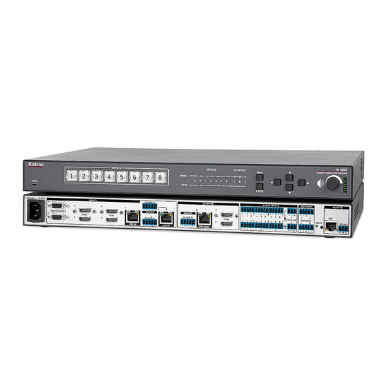
The Extron IN1608 Scaling Presentation Switcher is an eight input, HDCP-compliant
video scaler that accepts a wide variety of audio and video formats. This guide allows
an experienced user to set up and configure IN1608, IN1608 SA, and IN1608 MA
scalers. It covers how to perform basic operations using the front panel controls and
selected Simple Instruction Set (SIS™) commands.
NOTE:
For full installation, configuration, menus, connector wiring, and
operation details, see the IN1606 and IN1608 Series User Guide, at
www.extron.com.
Installation
Rear Panel Features
a
b
100-240V ~ 1.0 A MAX
1
3
CONFIGURABLE
2
HDMI
4
50-60 Hz
IN1608 Series Shared Rear Panel Connectors
Figure 1.
Power and Input Connections
a
AC power connector
b
Configurable analog 15-pin HD (VGA) connectors (inputs 1 and 2)
c
HDMI input connectors (inputs 3 through 6)
d
DTP input and corresponding RS-232/IR Over DTP connectors
(inputs 7 and 8)
e
Analog audio input connectors (associated with inputs 1 through 6)
f
Mic/Line audio input connectors and adjacent phantom power LEDs
Mounting and Cabling
Step 1 — Mounting
a.
Turn off or disconnect all equipment power sources.
b.
Mount IN1608 scalers to a rack using the pre-installed rack ears or use an optional
mounting kit for under-the-desk mounting. The IN1608 comes in a 1U, full rack width
enclosure. The IN1608 SA and IN1608 MA come in 2U, full rack width enclosures.
Step 2 — Connecting Inputs
a.
Connect analog video sources to the VGA connectors (see
Connect digital HDMI or DVI (with an appropriate adapter) sources to the HDMI
b.
c
connectors (see
c.
Connect a DTP transmitter to the DTP input connectors (see
and recommendations, see
on page 2.
Signal LED — Lights green when the unit is receiving an active video signal from a DTP
transmitter.
Link LED — Lights amber when a valid link is established to a DTP transmitter.
d.
To pass serial, infrared data, or other control signals, as for serial control of a source,
connect the control device to the RS-232 and IR Over DTP captive screw connectors
RS-232 and IR Over DTP Wiring
(see
e.
Connect analog audio input sources to the 5-pole captive screw connectors
e
(see
above). For audio wiring, see
f.
Connect Mic/Line audio input sources to the 3-pole captive screw connectors
f
(see
above).
c
d
INPUTS
RS-232
IR
5
7
8
Tx Rx
G
Tx Rx
SIG
LINK
SIG
OVER DTP
HDMI
RS-232
IR
6
DTP IN
DTP IN
Tx Rx
G
Tx Rx
above).
Twisted Pair Recommendations for DTP Communication
on page 2).
Audio Wiring
O
OUTPUTS
1
2
VARIABLE
L
R
g
h
OUTPUTS
C
A
LINK
SIG
LINK
L
OVER DTP
HDMI
RS-232
IR
L
B
Tx Rx
G
Tx Rx
DTP OUT
Output Connections
g
DTP output connector and
corresponding RS-232/IR Over
DTP connector (output C)
h
HDMI output connectors
(outputs A and B)
i
Analog audio output connectors
j
Amplified audio output connectors
(IN1608 SA and IN1608 MA only)
b
above).
d
above). For cable wiring
on page 2.
AMPLIFIED OUTPUT
2x25W(8Ω)/2x50W(4Ω)
L
R
OUTPUTS
O
10
1
CLASS 2 WIRING
REMOTE
LAN
VARIABLE
RESET
RS-232
L
Tx Rx
G
IN1608 SA
e
f i
AUDIO INPUTS
OUTPUTS
OUTPUTS
1
1
2
1
R
L
3
R
L
5
R
+48V
MIC/LINE
VARIABLE
2
R
L
4
R
L
6
R
2
L
R
+48V
Control Connections
k
LAN connector
l
RS-232 connector
Rack Ears
Rack Mounting
Mounting Screws
(2) Places
Each Side
#8 Screw
(4) Places
MBU 149
Each Side
Mounting Bracket
Furniture Mounting
AMPLIFIED OUTPUT
70V - 100W
2
CLASS 2 WIRING
REMOTE
LAN
RESET
R
RS-232
Tx Rx
G
IN1608 MA
k l
REMOTE
IN1608
LAN
RESET
RS-232
Tx Rx
G
1
Advertisement
Table of Contents

Related Manuals for Extron electronics in1608 series


Summary of Contents for Extron electronics in1608 series
-
Page 1: Rear Panel Features
RESET RESET RS-232 RS-232 NOTE: For full installation, configuration, menus, connector wiring, and Tx Rx Tx Rx operation details, see the IN1606 and IN1608 Series User Guide, at www.extron.com. Installation IN1608 SA IN1608 MA Rear Panel Features OUTPUTS REMOTE 100-240V ~ 1.0 A MAX... -
Page 2: Twisted Pair Recommendations For Dtp Communication
IN1608 Series • Setup Guide (Continued) Step 3 — Connecting outputs Connect a DTP receiver to the DTP output connector (see on page 1). For cable wiring and recommendations, see Twisted Pair Recommendations for DTP Communication below. Signal LED — Lights green when the IN1608 is outputting active video to a DTP receiver. -
Page 3: Front Panel Overview
Front Panel Overview Extron IN1608 INPUTS INPUTS OUTPUTS SCALING PRESENTATION SWITCHER MENU 1 2 3 4 5 6 7 8 SIGNAL CONFIG HDCP VOLUME ENTER Front Panel Features Figure 2. Front panel configuration port — Connect a host device to the mini USB B port for device configuration, control, and firmware upgrades. Input selection buttons (1-8) —... -
Page 4: Firmware Upgrades
Extron USA - West: +1.714.491.1500 FAX: +1.714.491.1517 +1.800.633.9876 (Inside USA/Canada Only) Extron USA - East: +1.919.850.1000 FAX: +1.919.850.1001 © 2013 Extron Electronics — All rights reserved. All trademarks mentioned are the property of their respective owners. www.extron.com 68-1916-50 Rev. A 06 13...
Need help?
Do you have a question about the in1608 series and is the answer not in the manual?
Questions and answers