Table of Contents
Advertisement
Quick Links
Advertisement
Table of Contents

Related Manuals for AXIOMTEK VTA-7570T


Summary of Contents for AXIOMTEK VTA-7570T
- Page 1 VTA-7570T ○ 5.7” QVGA Windows CE-based SCADA HMI User’s Manual...
- Page 2 AXIOMTEK assumes no responsibility for any inaccuracies that may be contained in this document. AXIOMTEK makes no commitment to update or to keep current the information contained in this manual. AXIOMTEK reserves the right to make improvements to this document and/or product at any time and without notice.
-
Page 3: Safety Approvals
Safety Approvals CE Marking FCC Class A FCC Compliance This equipment has been tested and complies with the limits for a Class A digital device, pursuant to Part 15 of the FCC Rules. These limits are designed to provide reasonable protection against harmful interference in a residential installation. -
Page 4: Safety Precautions
Safety Precautions Before getting started, read the following important cautions. 1. The VTA-7570T does not come equipped with an operating system. An operating system must be loaded first before installing any software into the computer. 2. Be sure to ground yourself to prevent static charge when installing the internal components. - Page 5 Trademarks Acknowledgments AXIOMTEK is a trademark of AXIOMTEK Co., Ltd. IBM, PC/AT, PS/2, VGA are trademarks of International Business Machines Corporation. Intel and Pentium are trademarks of Intel Corporation. MS-DOS, Microsoft C and Quick BASIC are trademarks of Microsoft Corporation.
- Page 6 This page does not contain any information.
-
Page 7: Table Of Contents
Table of Contents Disclaimers ...............ii Safety Approvals..............iii FCC Compliance..............iii Safety Precautions ............iv CHAPTER 1 INTRODUCTION ..........1 General Description ..........1 Specifications............2 1.2.1 Main CPU board..........2 1.2.2 I/O System ............2 1.2.3 System Specification........3 1.2.4 Software Specification........3 Dimensions ............ - Page 8 3.12 Load Optimized Defaults........33 3.13 Set Supervisor/User Password ......34 3.14 Save & Exit Setup ..........35 3.15 Exit Without Saving........... 36 CHAPTER 4 HMI RUNTIME USER GUIDE......38 Table of Contents viii...
-
Page 9: Chapter 1 Introduction
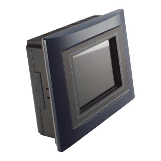
Dimensions I/O Outlets Package List General Description The VTA-7570T is a 5.7” fanless TFT QVGA touch panel computer. It is equipped with CISI-based low power consumption processor, AMD LX800. By supporting the option of external battery set, the VTA-7570T can continue system operation if a main power shortage ever happens. -
Page 10: Specifications
VTA-7570T User’s Manual Specifications 1.2.1 Main CPU board n CPU: AMD LX800 500MHz n System Chipset: AMD LX + CS5536AD n BIOS: Phoenix-Award 4Mbit with RPL/PXE Ethernet Boot ROM, Smartview and customer CMOS backup. n System Memory: One 184-pin DDR DIMM Maximum up to 1GB 1.2.2... -
Page 11: System Specification
VTA-7570T User’s Manual 1.2.3 System Specification 5.7” QVGA TFT LCD Disk drive housing: − Compact Flash Type II Socket DC 24V power supply Heat dispensing design Net weight: − 2.0 Kgs Dimension (main body size): − 208.5 x 167.3 x 66.5 mm Operating temperature: −... - Page 12 VTA-7570T User’s Manual Introduction...
-
Page 13: I/O Outlets
VTA-7570T User’s Manual I/O Outlets The following figure shows the I/O locations of the VTA-7570T. Power Switch DC power connector USB 2.0 x 2 COM 2 (RS-232) Line-out COM 1 (RS-232/422/485) CompactFlash card PC/104 slot Introduction... -
Page 14: Package List
VTA-7570T User’s Manual Package list When you receive the VTA-7570T, there are following items in the package. If you can not find it, please contact AXIOMTEK distributors. 1. VTA-7570T x 1 2. Panel mount kit x 6 3. Driver CD x1... -
Page 15: Chapter 2 Hardware Installation
VTA-7570T User’s Manual CHAPTER 2 HARDWARE INSTALLATION The VTA-7570T provides rich I/O ports and flexible expansions for you to meet different demand such as PCMCIA, WLAN module and so on. The chapter will show you how to install the hardware. It includes:... -
Page 16: Pc/104 Installation
1. Remove the rubber cover at left-side. 2. Install CompactFlash card in the VTA-7570T. PC/104 Installation The VTA-7570T offers a convenient expansion for users to install PC/104 module such as PCMCIA, WLAN, COM port card and so on. Hardware Installation... -
Page 17: Serial Port Interface
VTA-7570T User’s Manual Please follow the steps: 1. Unscrew screws to remove the bracket. 2. Install PC/104 module. Serial Port Interface VTA-7570T onboard serial ports, COM1 (RS-232/422/485) & COM2 (RS-232). Hardware Installation... -
Page 18: Ethernet
3-5, 4-6 RS-422 3-4, 7-8 1-3, 2-4 1-3, 2-4 RS-485 5-6, 7-8 1-3, 2-4 1-3, 2-4 COM2 COM1 Ethernet The VTA-7570T provides an NE2000 compatible Ethernet (RJ-45) interface. For network connection, just plug in one cable end of the Hardware Installation... -
Page 19: Mounting Way : Panel Mount
Rx- (Data reception negative) RJ-45 RJ45 termination RJ45 termination Mounting Way : Panel mount The VTA-7570T is designed for panel mount application. To mount the VTA-7570T, the standard set of mounting kit (included in the system packaging) is needed. Hardware Installation... -
Page 20: Chapter 3 Phoenix-Award Bios Utility
VTA-7570T User’s Manual CHAPTER 3 PHOENIX-AWARD BIOS UTILITY The Phoenix-Award BIOS provides users with a built-in Setup program to modify basic system configuration. All configured parameters are stored in a battery-backed-up RAM (CMOS RAM) to save the Setup information whenever the power is turned off. -
Page 21: Control Keys
VTA-7570T User’s Manual Control Keys Move cursor to the previous item Up arrow Move cursor to the next item Down arrow Move cursor to the item on the left hand Left arrow Move to the item in the right hand... -
Page 22: The Main Menu
VTA-7570T User’s Manual The Main Menu Once you enter the Award BIOS CMOS Setup Utility, the Main Menu appears on the screen. In the Main Menu, there are several Setup functions and a couple of Exit options for your selection. Use arrow keys to select the Setup Page you intend to configure then press <Enter>... -
Page 23: Standard Cmos Setup Menu
VTA-7570T User’s Manual 3.5 Standard CMOS Setup Menu The Standard CMOS Setup Menu displays basic information about your system. Use arrow keys to highlight each item, and use <PgUp> or <PgDn> key to select the value you want in each item. - Page 24 VTA-7570T User’s Manual l IDE Primary Master/Primary Slave These items identify the types of each IDE channel installed in the computer. There are 45 predefined types (Type 1 to Type 45) and 2 user’s definable types (Type User) for Enhanced IDE BIOS. Press <PgUp>/<+>...
- Page 25 VTA-7570T User’s Manual l Halt On This item determines whether the system will halt or not, if an error is detected while powering up. The system booting will halt on any errors detected. No errors (default) Whenever BIOS detects a non-fatal error, the All errors system will stop and you will be prompted.
-
Page 26: Advanced Bios Features
VTA-7570T User’s Manual Advanced BIOS Features This section allows you to configure and improve your system, to set up some system features according to your preference. l First/Second/Third Boot Device These items let you select the 1 , and 3 devices that the system will search for during its boot-up sequence. -
Page 27: Gate A20 Option
VTA-7570T User’s Manual l Gate A20 Option The default value is “Fast”. Normal The A20 signal is controlled by keyboard controller or chipset hardware. Fast Default: Fast. The A20 signal is controlled by Port 92 or chipset specific method. l Typematic Rate Setting This item determines the typematic rate of the keyboard. -
Page 28: Security Option
VTA-7570T User’s Manual l Security Option This item allows you to limit access to the system and Setup, or just to Setup. The default value is “Setup”. If a wrong password is entered at the prompt, the system System will not boot, the access to Setup will be denied, either. -
Page 29: Advanced Chipset Features
VTA-7570T User’s Manual 3.7 Advanced Chipset Features This section contains completely optimized chipset’s features on the board that you are strongly recommended to leave all items on this page at their default values unless you are very familiar with the technical specifications of your system hardware. -
Page 30: Flat Panel Configuration
VTA-7570T User’s Manual have to change the specifications of the installed DRAM or CPU. l Video Memory Size The available options are “8M”, “16M”, “32M”, “64M”, “128M” and “254M” l Output Display This item allows you to choose the output for your system display. -
Page 31: Integrated Peripherals
VTA-7570T User’s Manual Ø VSYNC Polarity Active The available options are “HI” and “LOW”. Ø SHFCLK Active Period Select the shift clock (SHFCLK) to be either free running, or active only during the display period. Some TFT panels recommend keeping the shift clock running during the retrace time. - Page 32 VTA-7570T User’s Manual l Super IO Device Scroll to this item and press <Enter> to view the sub menu Super IO Device. Ø Onboard Serial Port 1/2/3 Select an address and corresponding interrupt for the serial port. Options: 3F8/IRQ4, 2F8/IRQ3, 3E8/IRQ10, 2E8/IRQ11, 338/IRQ5, 238/IRQ7, Auto and Disabled.
- Page 33 VTA-7570T User’s Manual l IDE Function Setup Scroll to this item and press <Enter> to view the sub menu IDE Function Setup. Ø Master/Slave Drive PIO Mode The four IDE PIO (Programmed Input/Output) fields let you set a PIO mode (0-4) for each of the four IDE devices that the onboard IDE interface supports.
-
Page 34: Onboard Device
VTA-7570T User’s Manual block read/writes per sector the drive can support. Press <Esc> to return to the Integrated Peripherals page. l Onboard Device Scroll to this item and press <Enter> to view the sub menu Onboard Device. Ø Onboard Audio Use this item to enable or disable the onboard Audio function. - Page 35 VTA-7570T User’s Manual l ITE8888 Configure Scroll to this item and press <Enter> to view the sub menu ITE8888 Configure. Press <Esc> twice to return to the Main Menu page. PHOENIX-AWARD BIOS UTILITY...
-
Page 36: Power Management Setup
VTA-7570T User’s Manual 3.9 Power Management Setup The Power Management Setup allows you to save energy of your system effectively. It will shut down the hard disk and turn OFF video display after a period of inactivity. l ACPI Function This item allows you to enable/disable the Advanced Configuration and Power Management (ACPI). -
Page 37: Suspend Mode
VTA-7570T User’s Manual l Suspend Mode After a selected period of system inactivity (1 minute to 1 hour), all devices except the CPU shut off. The default value is “Disabled”. Disabled The System will never enter the SUSPEND mode. 1/2/4/6/8/10/2... -
Page 38: Pnp/Pci Configuration Setup
VTA-7570T User’s Manual 3.10 PnP/PCI Configuration Setup This section describes the configuration of PCI (Personal Computer Interconnect) bus system, which allows I/O devices to operate at speeds close to the CPU speed while communicating with other important components. This section covers very technical items that only experienced users could change default settings. -
Page 39: Irq Resources
VTA-7570T User’s Manual boot and Plug and Play-compatible devices. If you select Auto, all interrupt request (IRQ), DMA assignment, and Used DMA fields disappear, as the BIOS automatically assigns them. The default value is “Manual”. l IRQ Resources When resources are controlled manually, assign each system interrupt to... -
Page 40: Pc Health Status
VTA-7570T User’s Manual 3.11 PC Health Status This section supports hardware monitoring that lets you monitor those parameters for critical voltages, temperatures and fan speed of the board. l Current SYSTEM Temp Show you the current system temperature. l Current CPU Temp The current system CPU temperature will be automatically detected by the system. -
Page 41: Load Optimized Defaults
VTA-7570T User’s Manual 3.12 Load Optimized Defaults This option allows you to load your system configuration with default values. These default settings are optimized to enable high performance features. To load CMOS SRAM with SETUP default values, please enter “Y”. If not, please enter “N”. -
Page 42: Set Supervisor/User Password
VTA-7570T User’s Manual 3.13 Set Supervisor/User Password You can set a supervisor or user password, or both of them. The differences between them are: Supervisor password: You can enter and change the options on the setup menu. User password: You can just enter, but have no right to change the options on the setup menu. -
Page 43: Save & Exit Setup
VTA-7570T User’s Manual 3.14 Save & Exit Setup This section allows you to determine whether or not to accept your modifications. Type “Y” to quit the setup utility and save all changes into the CMOS memory. Type “N” to bring you back to the Setup utility. -
Page 44: Exit Without Saving
VTA-7570T User’s Manual 3.15 Exit Without Saving Select this option to exit the Setup utility without saving changes you have made in this session. Type “Y”, and it will quit the Setup utility without saving your modifications. Type “N” to return to the Setup utility. - Page 45 VTA-7570T User’s Manual MEMO PHOENIX-AWARD BIOS UTILITY...
-
Page 46: Chapter 4 Hmi Runtime User Guide
VTA-7570T User’s Manual CHAPTER 4 HMI RUNTIME USER GUIDE The AXIOMTEK HMI series is a PC-based industrial flat panel computer with a high luminance LCD and touch screen for most HMI applications. The HMI series products equipped with powerful processors feature low power consumption and low heat emissions especially for industrially rugged environments. - Page 47 VTA-7570T User’s Manual Run-time Shell introduction 1.Startup Screen HMI RUNTIME USER GUIDE...
- Page 48 VTA-7570T User’s Manual 2. Click Network button to setup the Ethernet setting HMI RUNTIME USER GUIDE...
- Page 49 VTA-7570T User’s Manual 3. Click Screen button to do the calibration of the touch screen HMI RUNTIME USER GUIDE...
- Page 50 VTA-7570T User’s Manual 4. Project Setting – manipulate the runtime project Click the “Project Backup” button to backup your runtime project into USB or internal storage. HMI RUNTIME USER GUIDE...
- Page 51 VTA-7570T User’s Manual Click the “Project Restore” to resort the backup project from internal storage or USB disk. HMI RUNTIME USER GUIDE...
- Page 52 VTA-7570T User’s Manual c.) Click the “Startup Setting” to setup the autorun application. You can setup the GDS parameter and loaded GPX project. HMI RUNTIME USER GUIDE...
- Page 53 VTA-7570T User’s Manual 5. Click the “Update” then the "Update Option” dialog will popup a.) Update OS – Copy the USB NK.bin into \HDD to update the CE OS. It is only useful in x86 based HMI. b.) Update App – Click this button to upgrade the WINPC32Pro runtime application.
- Page 54 VTA-7570T User’s Manual 6. Click the “Time Setting” to setup the system time. The system time is stored in RTC device. HMI RUNTIME USER GUIDE...
- Page 55 VTA-7570T User’s Manual 7. Click the “Utility” button, the Utility Option dialog will appear. Here are six functions. HMI RUNTIME USER GUIDE...
- Page 56 VTA-7570T User’s Manual System Setup – click this button to enter the SysSetup application shown as following. Configuration: you can setup the language, resolution, wallpaper and OS environment. WINPC32 Setup: you can setup the autorun project and parameter. RS-232: Test the COM-Ports utility...
- Page 57 VTA-7570T User’s Manual Click the “Register” to process the registration. Please send the Registration key back to supporter or get the unlock form the Registration Web Site. HMI RUNTIME USER GUIDE...
- Page 58 VTA-7570T User’s Manual c.) Click the “Save setting” button to store the registry setting into HDD. If you change the autorun setting and OS environment, you should press this button to save the setting. The same function is also implemented in SysSetup.exe and Register.exe.
- Page 59 VTA-7570T User’s Manual d.) Click the “Control Panel” to enter the OS control panel. HMI RUNTIME USER GUIDE...
- Page 60 VTA-7570T User’s Manual e.) Click the “Command Line” to enter the console mode. User can use the CE utility in this console. For example, the ping.exe tests the network. f.) Click the “Reboot” to reboot the HMI device. HMI RUNTIME USER GUIDE...
- Page 61 VTA-7570T User’s Manual HMI RUNTIME USER GUIDE...
- Page 62 VTA-7570T User’s Manual 8. Click the “OS” to enter WinCE OS. It requires the root account password. In general, this function is provided for power user and maintainer. HMI RUNTIME USER GUIDE...
- Page 63 VTA-7570T User’s Manual 9. Click “LaunchApp” to run exist project HMI RUNTIME USER GUIDE...
- Page 64 VTA-7570T User’s Manual HMI RUNTIME USER GUIDE...
- Page 65 VTA-7570T User’s Manual Windows CE Utility Windows CE utilities provided by AXIOMTEK including SystemSetup, GDS, GPX, Simulate Browser (have been included), GDS, GPX, WordPad and SystemSetup already have shortcut on desktop. Or, user can through Startà ProgramàWINPC32 Pro to access WINPC32 PRO CE run time application and utilities.
- Page 66 VTA-7570T User’s Manual The GDE Server (Global Data Exchange Server) is the WINPC32 Pro system run-engine. It operates the communicating PLCs, reading and writing the hardware signals and updating the memory status. GDS has several setting for different hardware. The setting consists of Run Type, CLK Type, hardware IRQ and hardware port address.
- Page 67 VTA-7570T User’s Manual In GPX Run-Mode, user can use (ATL+U) / (ATL + F4) to quit the GPX. User Program Auto Startup Setting In Windows CE, user can use System Setup (SysSetup.exe) utility to setting auto run program. HMI RUNTIME USER GUIDE...
- Page 68 VTA-7570T User’s Manual For example, we want to show a PowerPoint slice when system startup. Please press “Add” button and select Application file path. (PPT Viewer was located in \windows\presviewer.exe). HMI RUNTIME USER GUIDE...
- Page 69 VTA-7570T User’s Manual Specific full file path argument of PowerPoint data file. Press “OK”. HMI RUNTIME USER GUIDE...
- Page 70 VTA-7570T User’s Manual User can see presviewer.exe already been added in this List, press OK to Exit. Before we restart the Windows CE device, do not forget “Save Setting” to save the modification. HMI RUNTIME USER GUIDE...
- Page 71 VTA-7570T User’s Manual After system reboot, we can see the presentation document. HMI RUNTIME USER GUIDE...
Need help?
Do you have a question about the VTA-7570T and is the answer not in the manual?
Questions and answers