
Related Manuals for AXIOMTEK GOT810


Summary of Contents for AXIOMTEK GOT810
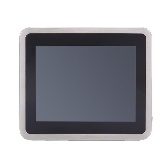
- Page 1 GOT810-845 10.4” XGA TFT Touch Panel Computer User’s Manual IP69K certification distinguishes the highest level of reliability...
-
Page 2: Disclaimers
Axiomtek does not make any commitment to update the information in this manual. Axiomtek reserves the right to change or revise this document and/or product at any time without notice. -
Page 3: Safety Precautions
Turn OFF the system power before cleaning. Clean the system using a cloth only. Do not spray any liquid cleaner directly onto the screen. The GOT810-845 may come with or w/o a touchscreen. Although the touchscreen is chemical resistant, it is recommended that you spray the liquid cleaner on a cloth first before wiping the screen. -
Page 4: Table Of Contents
USB Port ......................10 2.1.4 DC Power Jack w/ M12 connector ..............10 Water-proof Cables ..............11 2.2.1 Power cable ..................... 11 2.2.2 Power adapter for GOT810-845 ..............12 2.2.3 COM ......................... 13 2.2.4 USB cables ...................... 13 Mounting Method ..............14 2.3.1 VESA mounting .................... - Page 5 3.4.2 South Bridge ....................28 Security Menu ................29 Boot Menu ................. 30 Save & Exit Menu ..............31 CHAPTER 4 Drivers Installation ..........33 System ..................33 4.1.1 Win 7 ........................ 33 4.1.2 Win 8/8.x ......................34 Touch Screen ................35 4.2.1 Specification .....................
- Page 6 This page is intentionally left blank.
-
Page 7: Chapter 1 Introduction
Package List General Description The GOT810-845 is a fan-less and compact-size touch panel computer, equipped with a 10.4” XGA TFT LCD display and an Intel® Pentium® Processor N3060 (2M Cache, 1.60 GHz), providing excellent computing performance and thermal resistance. This fanless platform is especially designed for space-limited applications in food and beverage industry. -
Page 8: Specifications
GOT810-845 User’s Manual Specifications 1.2.1 Main CPU Board Intel® Pentium® Processor N3060 (2M Cache, 1.60 GHz) onboard System Memory One 204-pin DDR3L SO-DIMM socket Maximum memory up to 8GB BIOS AMI UEFI BIOS ... -
Page 9: System Specification
Vibration 2G / 10 ~ 500Hz / operation (SSD/mSATA, random) 1. All specifications and images are subject to change without notice. 2. The GOT810-845 is suited on serious environment; please choose the wide temperature DRAM and SSD. Note ℃... -
Page 10: Dimensions
GOT810-845 User’s Manual Dimensions This diagram shows you dimensions and outlines of the GOT810-845. Introduction... -
Page 11: I/O Outlets
GOT810-845 User’s Manual I/O Outlets Please refer to the following illustration for I/O locations of the GOT810-845. Function Backlight ON/OFF Brightness Adjust Power Switch(ATX) Ventilation valve DC power connector (A-coded) COM1(configure RS422/485, default RS-232, A-code) COM2(RS232 Only, A-code) USB2.0 × 2 (A-code) -
Page 12: Antenna Installation (Optional)
GOT810-845 User’s Manual Antenna installation (optional) If you have the optional wireless module, you will find the antenna in the accessory box. The installation instructions are as follows Introduction... -
Page 13: Package List
Water-proof Power / USB / LAN / RS-232 cables (optional) Water-proof Antenna for Wifi or UMTS/HSPA+ (optional) VESA ARM(optional) If you can not find the package or any items are missing, please contact Axiomtek distributors immediately. Introduction... - Page 14 GOT810-845 User’s Manual This page is intentionally left blank. Introduction...
-
Page 15: Chapter 2 System Configurations
GOT815-834 User’s Manual CHAPTER 2 System Configurations The GOT810-845 provides rich I/O ports and flexible expansions for you to meet different demand, for example, CF. The chapter will show you how to install the hardware. It includes: I/O Pin Assignment ... -
Page 16: Ethernet
GOT810-845 User’s Manual 2.1.2 Ethernet The GOT810-845 is equipped with a high performance Plug and Play Ethernet interface, full compliant with IEEE 802.3 standard, and can be connected with a M12 X-CODE LAN connector. Please refer to detailed pin assignment list below:... -
Page 17: Water-Proof Cables
GOT-800 series uses specific M12 connector for water-proof. Therefore you will order each cable base on application. There are four kind cables of GOT810, by the optional, if you will apply the USB, COM or Etherent then you can select a cable for the package. -
Page 18: Power Adapter For Got810-845
GOT810-845 User’s Manual 2.2.2 Power adapter for GOT810-845 If you order the power adapter, you should choose the power cord type for your location. The power adapter is +24VDC(90W), 110-240V which is combined M12 connector. The power adapter is +24VDC(60W), 110-240V which is combined M12 connector. -
Page 19: Com
GOT815-834 User’s Manual 2.2.3 COM There are two COM cables which are combined M12 connector. Also, you can refer 2.1.1 for the Series port pin assignement. 2.2.4 USB cables The USB cable is combined M12 connector for water-proof. It is extended two USB ports for applicaton. -
Page 20: Mounting Method
GOT810-845 User’s Manual Mounting Method There are two mounting ways for the GOT810-845. One is suspension, the other is VESA mount. 2.3.1 VESA mounting The GOT810 can accept VESA 100. System Configurations... -
Page 21: Vesa-Arm Mounting
GOT815-834 User’s Manual 2.3.2 VESA-ARM Mounting Step 1 Find out the 4 screws as marked on the back side of chassis. Step 2 Assemble the VESA-ARM to the back side of the chassis, and fix the screws. Step 3 VESA mounting Installation completed. System Configurations... - Page 22 GOT810-845 User’s Manual This page is intentionally left blank. System Configurations...
-
Page 23: Chapter 3 Ami Bios Setup Utility
GOT815-834 User’s Manual CHAPTER 3 AMI BIOS Setup Utility This Section provides users with detailed descriptions about how to set up basic system configurations through the AMI BIOS setup utility. Navigation Keys The BIOS setup/utility uses a key-based navigation system called hot keys. Most of the hot keys for the BIOS setup utility can be used at any time during the setup navigation process. -
Page 24: Main Menu
GOT810-845 User’s Manual Main Menu Figure 3-1 Main menu System Date / Time Use this option to change the system time and date. Highlight System Time or System Date using the up/ down/ left and right arrow keys (see Figure 3-1). Enter new values through the keyboard. -
Page 25: Advanced Menu
GOT815-834 User’s Manual Advanced Menu Figure 3-2 Advanced Menu The Advanced menu allows users to set configurations of the CPU and other system devices. Select any item on the left to go to the sub-menus (as shown in Figure 3-2). ►... -
Page 26: Nct6106D Super Io Configuration
GOT810-845 User’s Manual 3.3.1 NCT6106D Super IO Configuration The ‘NCT6106D Super IO Configuration’ page is to change the value of the Super IO Configuration. The description of the selected item will appear on the right side of the screen (as shown in Figure 3-3). For items marked with “”, please press <Enter> for further options (as shown in Figure 3-4). -
Page 27: Hardware Monitor
GOT815-834 User’s Manual COM Port Type This option is used to select COM Port Type: RS-232/422/ or 485. Figure 3-4 ‘NCT6106D Super IO Configuration’ -> ‘Serial Port 1 (COM1)’ 3.3.2 Hardware Monitor Figure 3-5 shows a screen reflecting the health status of the hardware in real time. Figure 3-5 Entering ‘Hardware Monitor’... - Page 28 GOT810-845 User’s Manual selected option. A description of the selected item appears on the right side of the screen. ACPI Sleep State This item allows users to select the Advanced Configuration and Power Interface (ACPI) state to be used for system suspension. There are two choices under this selection: Suspend Disable and S3 (Suspend to RAM) (as shown in Figure 3-6).
-
Page 29: Cpu Configuration
GOT815-834 User’s Manual 3.3.4 CPU Configuration Figure 3-7 shows a page of CPU configuration with item Intel Virtualization Technology [enable/disable] highlighted. Figure 3-7 Entering ‘CPU Configuration’ AMI BIOS Setup Utility... -
Page 30: Sata Configuration
GOT810-845 User’s Manual 3.3.5 SATA Configuration This screen allows users to select options for SATA Configuration, and change the value of the selected option (see Figure 3-8). SATA Controller Highlight this item to set up SATA Controller to be Enable or Disable. -
Page 31: Usb Configuration
GOT815-834 User’s Manual 3.3.6 USB Configuration Please see Figure 3-9 to see what items can be set up under the page of USB Configuration. Figure 3-9 Entering ‘USB Configuration’ 3.3.7 Utility Configuration Figure 3-10 shows the page once entering Utility Configuration. Figure 3-10 Entering ‘Utility Configuration’... -
Page 32: Pcie/Msata Mini Card Configuration
GOT810-845 User’s Manual 3.3.8 PCIE/mSATA Mini Card Configuration Highlighting item PCIE/mSATA Mini Card Configuration under the Advanced Menu, hit <Enter> to enter a sub-screen as shown in Figure 3-11. There are two choices for Mino Card Mode: PCIE and mSATA. -
Page 33: Chipset Menu
GOT815-834 User’s Manual Chipset Menu The Chipset menu gives memory information about the North Bridge and TXE information about the South Bridge (see Figure 3-12). Figure 3-12 Chipset Menu 3.4.1 North Bridge Memory information about the North Bridge is show in Figure 3-13. Figure 3-13 Entering ‘North Bridge’... -
Page 34: South Bridge
GOT810-845 User’s Manual 3.4.2 South Bridge TXE information about the South Bridge is show in Figure 3-14. Figure 3-14 Entering ‘South Bridge’ AMI BIOS Setup Utility... -
Page 35: Security Menu
GOT815-834 User’s Manual Security Menu Figure 3-15 Security Menu AMI BIOS Setup Utility... -
Page 36: Boot Menu
GOT810-845 User’s Manual Boot Menu The Boot menu allows users to change boot options of the system. Users can highlight any of the items on the left frame of the screen to go to any particular sub menus (as shown in Figure 3-16). -
Page 37: Save & Exit Menu
GOT815-834 User’s Manual Save & Exit Menu Save & Exit Menu Figure 3-17 AMI BIOS Setup Utility... - Page 38 GOT810-845 User’s Manual This page is intentionally left blank AMI BIOS Setup Utility...
-
Page 39: Chapter 4 Drivers Installation
CHAPTER 4 Drivers Installation System GOT810-845 supports W indows 7, W indows 8/8.1,W ES 7 and W E8S. To facilitate the installation of system driver, please car efully read the instructions in this chapter before start installing. 4.1.1 Win 7 Insert Driver CD and select the “\Drivers”. -
Page 40: Win 8/8.X
GOT810-845 User’s Manual 4.1.2 Win 8/8.x Insert Driver CD and select the “\Drivers”. Select all files and follow the installing procedure. If you didn’t install graphics driver, it only can be resumed via V GA display when VGA and DP go to sleep mode. -
Page 41: Touch Screen
Active: 24.6mA / Idle Mode: 13.4mA 4.2.2 Driver Installation- Windows 7/8.x The GOT810-845 provides a touch screen driver that users can install it under the operating system W indows 7/8.x. To facilitate installation of the touch screen driver, you should read the instructions in this chapte r carefully before you attempt installation. - Page 42 GOT810-845 User’s Manual Select the “Standard Calibrate” tab. Calibration: To adjust the display with touch panel, click “Calibration” and follow the calibrate point to do calibration; there are five points on screen for calibration. Press OK. Drivers Installation...
-
Page 43: Embedded O.s
GOT815-834 User’s Manual Embedded O.S. The GOT810-845 provides the W ES 7 and W E8S Embedded. The O.S. is supported devices which are listed below. 4.3.1 WES 7 & WE8S Here are supported onboard devices: Onboard Multi I/O SATA HDD ... - Page 44 GOT810-845 User’s Manual This page is intentionally left blank. Drivers Installation...
Need help?
Do you have a question about the GOT810 and is the answer not in the manual?
Questions and answers