
Related Manuals for Mellanox Technologies SX10XX


Summary of Contents for Mellanox Technologies SX10XX
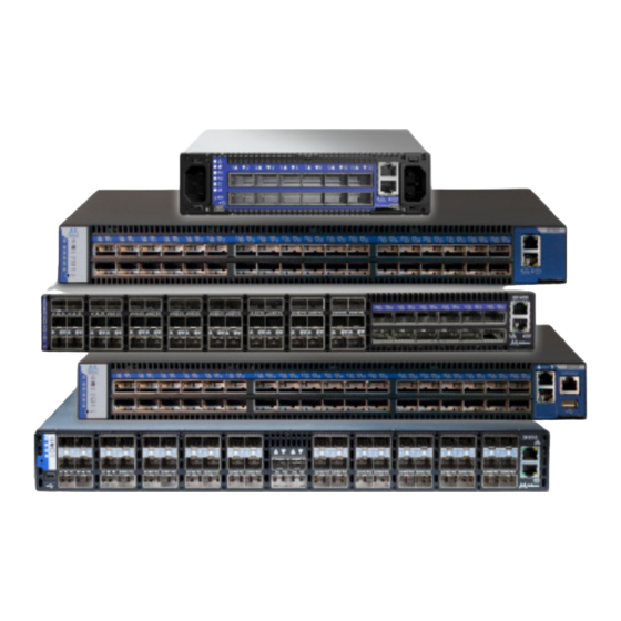
- Page 1 Mellanox SX10XX/SX1X00 1U Switch Systems Hardware User Manual Rev. 1.1 www.mellanox.com...
- Page 2 KIND AND SOLELY FOR THE PURPOSE OF AIDING THE CUSTOMER IN TESTING APPLICATIONS THAT USE THE PRODUCTS IN DESIGNATED SOLUTIONS. THE CUSTOMER'S MANUFACTURING TEST ENVIRONMENT HAS NOT MET THE STANDARDS SET BY MELLANOX TECHNOLOGIES TO FULLY QUALIFY THE PRODUCTO(S) AND/OR THE SYSTEM USING IT. THEREFORE, MELLANOX TECHNOLOGIES CANNOT AND DOES NOT GUARANTEE OR WARRANT THAT THE PRODUCTS WILL OPERATE WITH THE HIGHEST QUALITY.
-
Page 3: Table Of Contents
About this Manual ............3 Chapter 1 Introduction to Mellanox SX10XX/SX1X00 Systems ....5 1.1 Overview . - Page 4 E.10 Avvertenze di sicurezza per l’installazione (italiano) ....97 E.11 Montaj Güvenlik Uyarıları (Türkçe) ......102 Mellanox Technologies...
- Page 5 Figure 36: Pull-out Tab ............49 Mellanox Technologies...
- Page 6 Figure 39: RJ45 to DB9 Harness Pinout ..........67 Mellanox Technologies...
- Page 7 RJ-45 I2C Pinout ............66 Mellanox Technologies...
-
Page 8: Revision History
Revision History Table 1 - Revision History Table Date Revision Description January 2015 Minor formatting edits January 2015 First release of the new edition Mellanox Technologies... -
Page 9: About This Manual
For possible hardware issues see the switch support product page. This Hardware Release Notes document can be found on the support web page for this product. MLNX-OS® User Manual This document contains information regarding configuring and manag- ing MLNX-OS software- see http://www.mellanox.com/page/mlnx_os. Mellanox Technologies... - Page 10 This icon makes recommendations to the user. This icon indicates information that is helpful to the user. This icon indicates a situation that can potentially cause personal injury or damage to hardware or software. Risk of electrick shock! Mellanox Technologies...
-
Page 11: Chapter 1 Introduction To Mellanox Sx10Xx/Sx1X00 Systems
Introduction to Mellanox SX10XX/SX1X00 Systems Overview Mellanox Ethernet System Family delivers the highest performance and port density with a com- plete chassis and fabric management solution enabling converged data centers to operate at any scale while reducing operational costs and infrastructure complexity. This family includes a broad portfolio of Top-of-Rack (TOR) systems that range from 12 to 64 ports, and support 10/40/ 56Gb/s per port. -
Page 12: Management Interfaces And Frus
Introduction to Mellanox SX10XX/SX1X00 Systems Management Interfaces and FRUs Table 4 lists the various management interfaces and available replacement parts per system model. Table 4 - Management Interfaces and FRUs System Replaceable Replaceable Ports Ports Console Model Qty. Location SX1012... -
Page 13: Features
• Link Aggregation/LACP (802.3ad) • Flow Control • Global flow control (802.3a) • Priority based Flow Control (802.1Qbb) • DCBx 1.4.3 IP Features (L3) • Static Routes • OSPF • ECMP • VLAN interface for routing • DHCP Relay Mellanox Technologies... -
Page 14: Certifications
Introduction to Mellanox SX10XX/SX1X00 Systems • BGP Certifications The list of certifications (such as EMC, Safety and others) per system for different regions of the world is located on the Mellanox website at: http://www.mellanox.com/page/environmental_compliance Ordering Information the following table lists ordering information for the available systems. Please pay attention to the airflow direction when ordering your system. - Page 15 2 Power Supplies (AC), x86 quad core, standard depth, P2C airflow, Rail kit, RoHS6 MSX1700-BS2R2 SwitchX®-2 based 40GbE, 1U Open Ethernet Switch with MLNX-OS, 36 QSFP+ ports, 2 Power Supplies (AC), x86 quad core, standard depth, C2P airflow, Rail kit, RoHS6 Mellanox Technologies...
-
Page 16: Chapter 2 Installation
(Romanian),” on page 90. For Safety Warnings in Croatian see Section E.9, “Sigurnosna upozorenja za instaliranje (Croa- tian),” on page 94. For Safety Warnings in Italian see Section E.10, “Avvertenze di sicurezza per l’installazione (italiano),” on page 97. Mellanox Technologies... -
Page 17: Air Flow
Table 6 provides an air flow label color legend and respective OPN designations, Table 6 - Air Flow Label Legend Label Direction Description Designation Connector side inlet to power side outlet. Red labels are placed on the power inlet side. Mellanox Technologies... -
Page 18: Figure 2: Air Flow Direction Marking - Connector Side Inlet To Power Side Outlet
Blue labels are placed on the power inlet side. Figure 2: Air Flow Direction Marking - Connector Side Inlet to Power Side Outlet Figure 3: Air Flow Direction Marking - Power Side Inlet to Connector Side Outlet Mellanox Technologies... -
Page 19: Package Contents
• 1 – Power cable for each power supply unit – Type C13-C14 • 1 – Harness: HAR000028 – Harness RS232 2M cable – DB9 to RJ-45 • 1 – Quick Start Guide If anything is damaged or missing, contact your sales representative at support@mella- nox.com. Mellanox Technologies... -
Page 20: Mounting Options
• Two system slides • 16 recessed flat head screws (with extras) • 10 caged nuts • 10 pan head screws (M6) Figure 4: Rack Rail Kit Parts System slide x2 Rail x2 Rail slide x2 Nuts and bolts Screws Mellanox Technologies... -
Page 21: Figure 5: Screwing On The Rail
If using a torque screwdriver to tighten the screws, set it to 0.85Nm. Clip the caged nuts into the holes in the rack on the side of the rack you will be sliding the sys- Step 3. tem into. Mellanox Technologies... -
Page 22: Figure 6: Inserting The Caged Nuts
Figure 7: Slide the Rail into the Rail Slide This side of the rail kit goes on the side of the rack you will slide the system into. This is the same side of the system that will be next to the vertical support. Mellanox Technologies... -
Page 23: Figure 8: Installing The Slides
Figure 8: Installing the Slides Slide the system into the rails. Step 6. Place the system and screw the bolts into the nuts. Tighten the bolts to 9.2 Nm or 81.5 pound Step 7. inches. Mellanox Technologies... -
Page 24: Figure 9: System Placement In The Rack
Installation Figure 9: System Placement in the Rack Figure 10: Installation Completed Mellanox Technologies... -
Page 25: Side-By-Side
The installation kits come with enough system mounted rails and flat head screws to install two systems. The 2 system frames will fit into racks with from 21” (533mm) to 34” (864mm) between the ver- tical supports. Figure 11: Installation Kit Parts for a Side by Side Installation Mellanox Technologies... -
Page 26: Figure 12: Screw On The System Mounted Rails
Screw the two systems mounted rails to the system, using six flat head screws per rail. Step 2. Figure 12: Screw on the System Mounted Rails Install the two system frame into the rack. Slide the frame slides into the frame. Step 1. Mellanox Technologies... -
Page 27: Figure 13: Two Systems Frame
Place the frame in the rack. Both sides of the frame must be on the inside of the rack. Step 2. Figure 14: Placement of Frame in the Rack Take the 10 spacer bushings and use them to adapt the square openings in the vertical support. Step 3. Mellanox Technologies... -
Page 28: Figure 15: Placing The Spacer In The Rack
Use the 10 M5 pan head screws. Do not tighten the screws to the frame. Step 4. Using the Spacer Bushings Step 5. Slide the system into the frame, and screw in the capture bolts into the frame. Step 6. Mellanox Technologies... -
Page 29: Figure 16: Insert System Into Frame
Included in the box is a bag with 4 rubber stick-on feet for table top installation. Table Top Installation Peel and stick the four rubber bumpers into the bottom of the system. Place them in the round Step 1. circles. Mellanox Technologies... -
Page 30: Figure 17: Placing The Bumpers
Figure 17: Placing the Bumpers Bottom of the system Place on a flat surface. Make sure the system sits solid on the surface. Step 2. Connect the power cord. Step 3. Connect the data transfer cables. Step 4. Mellanox Technologies... -
Page 31: Grounding
Test the ground using an Ohm meter. Some national and/or local codes may require IT components to be bonded and exter- nally grounded (not including the power cord ground). You must follow all national and local codes when installing this equipment. Mellanox Technologies... -
Page 32: Cable Installation
When using this feature you should login into the MLNX-OS® CLI and configure the individual ports to be ‘split-2’ or ‘split-4’. Mellanox Technologies... -
Page 33: Figure 19: Breakout Or Fanout Cable
In this switch, all ports can be split to 4x10GbE, no limitation. 2.6.1.2 SX1024/SX1400 Figure 20: SX1024/SX1400 Port Splitting Options This port can be split into 4 or 2 10Gb/s SFP+ This port is unmapped according to the Port Splitting Table Mellanox Technologies... -
Page 34: Figure 21: Sx1036 Port Splitting Options
Yes, disables port 24 Yes, disables port 12 Yes, disables port 30 Yes, disables port 7 Yes, disables port 25 Yes, disables port 13 — Yes, disables port 31 Yes, disables port 18 — Yes, disables port 36 Mellanox Technologies... -
Page 35: Figure 22: Examples Of Port Mapping Assignment
= 00 10GbE ports + 00 40GbE ports THESE PORTS 12 x 40GbE ports split to 4 10GbE ports = 48 10GbE ports 12 x 40GbE ports used as 40GbE ports = 12 40GbE ports Total = 48 x 10GbE and 12 x 40GbE Mellanox Technologies... -
Page 36: Sfp+ Removal Tool
Yes, disables port 35 SFP+ Removal Tool There is a special tool to remove SFP+ cables from switches (such as SX1016 and SX1024/ SX1400) with 3 rows of SFP+ ports. To remove SFP+ cables follow the instruction in the figure below. Mellanox Technologies... -
Page 37: Figure 24: Sfp+ Removal And Insertion Tool
Figure 24: SFP+ Removal and Insertion Tool Mellanox Technologies... -
Page 38: Initial Power On
Mellanox representative for assistance. Check the System Status LEDs and confirm that all of the LEDs show status lights consistent Step 4. with normal operation, as shown in Figure 25 below. For more information, refer to “LEDs” on page 43. Mellanox Technologies... -
Page 39: Figure 25: System Status Leds 5 Minutes After Power On
Einhieten spannungs- ensure a powered down state “Alimentation Stabilise’e”. frei zu machen sind die inside of the switch platform. Pour isoler completement le Netzstecker aller Netzteile module en cause, Il faut zu entfernen de’brancher toutes les alimen- tations stabilise’es. Mellanox Technologies... -
Page 40: System Bring-Up
Login as admin and use admin as password. On the first login, the MLNX-OS configuration Step 3. wizard will start. To configure network attributes and other initial parameters to the system, follow the configu- Step 4. ration wizard as shown in Table Mellanox Technologies... -
Page 41: Table 11: Configuration Wizard Session - Dhcp
<enter> to save changes and exit. To re-run the configuration wizard, run the command “configura- Choice: <Enter> tion jump-start” in Config mode. Configuration changes saved. The table below shows an example of static IP configuration for mgmt0 interface. Mellanox Technologies... -
Page 42: Table 12: Configuration Wizard Session - Static Ip Configuration
To change an answer, enter the step number to return to. Otherwise hit <enter> to save changes and exit. Choice: Configuration changes saved. To return to the wizard from the CLI, enter the “configuration jump-start” command from configure mode. Launching CLI... > Mellanox Technologies... -
Page 43: Remote Connection
Set up an Ethernet connection between the system and a local network machine using a stan- Step 1. dard RJ45 connector. Start a remote secured shell (SSH) using the command: “ssh -l <username> <IP_address>”, Step 2. # ssh -l <username> <ip address> Mellanox Technologies... -
Page 44: Fru Replacements
Grasping the handle with your right hand, push the latch release with your thumb while pulling Step 2. the handle outward. As the power supply unit unseats, the power supply unit status LEDs will turn off. Remove the power supply unit. Step 3. Mellanox Technologies... -
Page 45: Figure 27: Power Supply Unit Extraction
Insert the other end of the power cord into an outlet of the correct voltage. Step 5. The green power supply unit indicator should light. If not, repeat the whole procedure to extract the power supply unit and re-insert it. Mellanox Technologies... -
Page 46: Figure 29: Fan Module Latches
The green Fan Status LED should light. If not, extract the fan unit and reinsert it. After system two unsuccessful attempts to install the fan unit, power off the before attempt- ing any system debug. Mellanox Technologies... -
Page 47: Chapter 3 Interfaces
RS232 serial port used for initial configuration and debugging. Upon first installation of the system, you need to connect a PC to this interface and configure network parameters for remote connections. Refer to Section 2.9.1 to view the full pro- Mellanox Technologies... -
Page 48: Management
3.1.6 The I2C connector is located either on the power supply side (banana connector), or on the front side (RJ45 connector). The I2C interface is used for debugging and is intended for Mellanox debug person- nel only. Mellanox Technologies... -
Page 49: Reset Button
• Port LEDs The Status LEDs are located to the left side of the front panel and on the power side at the far right. The port LEDs are located on top of the data ports- see Section 3.2. Mellanox Technologies... -
Page 50: Figure 30: System Status Leds - Front And Rear Sides
Both of the System Status LEDs (front and back) supply identical information. It may take up to five minutes to turn on the system. If the System Status LED shows red after five minutes, unplug the system and call your Mellanox representative for assistance. Mellanox Technologies... -
Page 51: Figure 31: Fan Status Led - Front And Rear Sides
Figure 31: Fan Status LED - Front and Rear sides Mellanox ® This is a two color LED Table 15 - Fan Status LED Assignments Description Action Required Behavior Solid Green All fans are up and running (normal condition). Mellanox Technologies... -
Page 52: Figure 32: Power Status Led
Each power supply unit has a single 2 color LED on the right side of the unit, that indicates the status of the unit. In SX1024 and SX1400 PS1 and PS2 are combined into one LED. Figure 33: Rear Side Panel Power Supply Unit Mellanox Technologies... -
Page 53: Table 16: Power Supply Unit Status Led Assignments
3.2.1.5 UID LED The UID LED is a debug feature, that, upon user configuration, lights a blue LED for ease in finding a particular system within a cluster. This is a future feature that is not yet available. Mellanox Technologies... -
Page 54: Figure 34: Sfp+ Port Led Assignment
The SFP+ ports come three rows to a column. The LEDs refer to the ports according to the color coding in Figure 34. Figure 34: SFP+ Port LED Assignment 43 44 45 47 48 Figure 35: Port LEDs Mellanox Technologies... -
Page 55: Inventory Pull-Out Tab
The system’s inventory parameters (such as serial number, part number and MAC address) can be extracted from the Inventory pull-out tab on the lower right side of the front panel. SX1016 does not contain an inventory pull-out tab. Figure 36: Pull-out Tab Mellanox Technologies... -
Page 56: Chapter 4 Software Management
SwitchX®-2 based managed systems. MLNX-OS® includes a CLI, WebUI, SNMP, system management software and IB management software (OpenSM). The Ethernet ports for remote management connect to Ethernet systems. These sys- tems must be configured to 100Mb/1 Gb auto-negotiation. Mellanox Technologies... -
Page 57: Chapter 5 Troubleshooting
Check that the FAN is fully inserted and nothing blocks the airflow. • Replace the FAN FRU if needed. PSU Status LED is red This state is indicative of a problem with the PSU. • Check/replace the power cable. • Replace the PSU if needed. Mellanox Technologies... - Page 58 PCIE1: successfully set as root-complex 01 00 15b3 bd34 0c06 00 Net: ppc_4xx_eth0, ppc_4xx_eth1 Hit Ctrl+B to stop autoboot: 0 Mellanox MLNX-OS Boot Menu: 1. SX_PPC_M460EX 3.3.5006-dev-HA 2013-04- 10 12:02:49 ppc 2. SX_PPC_M460EX 3.3.5006-dev-HA 2013-04- 11 14:05:39 ppc 3. U-Boot prompt Choice: Mellanox Technologies...
- Page 59 Press enter to boot the selected image or 'p' to enter a password to unlock the next set of features. Highlighted entry is 0: " • Select previous image to boot by pressing an arrow key and choosing the appropriate image. Mellanox Technologies...
-
Page 60: Specificationssx1012 Series
Input Voltage: 100 - 240 VAC 50-60Hz Max Consumption: Passive cables: 136W Active Cables: 163W Optical Cables: 168W Typical (ATIS score under "snake" topology): With passive cables: 49.13W CPU and Switch CPU: PPC460EX Switch: Mellanox SwitchX® Switching Capacity: 1.34 Tb/s non-blocking Mellanox Technologies... -
Page 61: Sx1016 Series
Power Input Voltage: 100 - 240 VAC 50-60Hz Max Consumption: Active Cables: 239.53 Passive cables: 156.84 Typical (ATIS score under "snake" topology): With passive cables: 63.99W Main Devices CPU: PPC460EX Switch: Mellanox SwitchX Switching Capacity: 1.28 Tb/s non-blocking Mellanox Technologies... -
Page 62: Chapter 6 Sx1024 Series
Input Voltage: 100 - 240 VAC 50-60Hz Max Consumption: Passive cables: 175 W Active Cables: 263 W Optical cables: 267 W Typical (ATIS score under "snake" topology): With passive cables: 73.15 Main Devices CPU: PPC460EX Switch: Mellanox SwitchX® Switching Capacity: 1.92 Tb/s non-blocking Mellanox Technologies... -
Page 63: Sx1400 Series
Temperature: Operating: 0° to 45°C Storage: -40° to 70°C Altitude: Operating: 3200m Storage: 3200m Power 100-240VAC Input Voltage: Typical (ATIS score under "snake" topology): With passive cables: 83.3 Main Devices CPU: Intel CORE I7-3612QE (x86) Switch: Mellanox SwitchX® Mellanox Technologies... -
Page 64: Sx1036 Series
Input Voltage: 100 - 240 VAC 50-60Hz Max Consumption: Active Cables: 224W – 6.2 W/port Passive cables: 119W – 3.3W/port Typ Consumption: Active Cables: 182W – 5W/port Passive cables: 100W – 2.8W/port Main Devices CPU: PPC460EX Switch: Mellanox SwitchX® Switching Capacity: 4.03 Tb/s non-blocking Mellanox Technologies... -
Page 65: Sx1700 Series
Mounting: 19” Rack mount Weight: System with 1PSU: 7.90kg/17.41lbs System with 2PSUs: 8.80kg/19.40lbs Speed: 40/56GbE per port Connector cage: 36 QSFP+ Environmental Altitude: Operating: 3200m Storage: 3200m Power Input Voltage: 100-240VAC Main Devices CPU: Intel CORE I7-3612QE (x86) Switch: Mellanox SwitchX® Mellanox Technologies... -
Page 66: Appendix A Accessory And Replacement Parts
1U systems to be mounted into standard depth racks MTUSB-1 C DB9 or RJ-45 to USB adapter (located in EVB products only) HAR000028 Harness RS232 2M cable – DB9 to RJ-45 (for managed switches only) ACC000501 Power cord Type C13-C14 Mellanox Technologies... -
Page 67: Appendix B Thermal Threshold Definitions
When the SwitchX® device crosses this temperature, the firmware will automatically shut down the device. 3.Emergency – 130C In case the firmware fails to shut down the SwitchX® device upon crossing the Critical thresh- old, the SwitchX® device will auto-shutdown upon crossing the Emergency (130C) threshold. Mellanox Technologies... -
Page 68: Appendix C Interface Specifications
Vcc Tx +3.3 V Power supply transmitter Vcc 1 +3.3 V Power Supply LPMode Low Power Mode Ground Tx3p Transmitter Non-Inverted Data Input Tx3n Transmitter Inverted Data Input Ground Tx1p Transmitter Non-Inverted Data Input Tx1n Transmitter Inverted Data Input Mellanox Technologies... - Page 69 Figure 37: QSFP Connector Male and Female Views 18.35 View into Rear of Connector 8.50 18.35 View into Front of Cage 8.50 Mellanox Technologies...
-
Page 70: Sfp+ Interface
SFP+ Interface 56.50 13.90 Mellanox Technologies 11.85 13.60 14.80 13.70 MTSFPP-SR Module 1.55 0.50 8.50 0.60 2.55 1.80 44.95 Figure 38: Rear View of Module With Pin Placement 13.70 8.50 Symbol Name Description VeeT Transmitter Ground (Common with Receiver Ground) TX_Fault Transmitter Fault. - Page 71 MOD_ABS pulls line low to indicate module is plugged in. e. LOS is open collector output. Should be pulled up with 4.7kΩ – 10kΩ on host board to a voltage between 2.0V and 3.6V. Logic 0 indicates normal operation; logic 1 indicates loss of signal. Mellanox Technologies...
-
Page 72: Rj-45 Console And I2C Interface
Looking into the Socket Bl/W RXD- RJ-45_RXD Br/W Table 28 - RJ-45 I2C Pinout Connection Signal Pin# Color TXD+ RJ-45_SDA TXD- RXD+ TXD+ Pin 1 TXD- RJ45_SDA Bl/W RXD+ RXD- RJ-45_SCL RXD- RJ45_SCL Br/W Pin 8 Looking into the Socket Mellanox Technologies... -
Page 73: C.4 Rj45 To Db9 Harness Pinout
RJ45 to DB9 Harness Pinout In order to connect a host PC to the Console RJ45 port of the system, a RS232 harness cable (DB9 to RJ45) is supplied. Figure 39: RJ45 to DB9 Harness Pinout Mellanox Technologies... -
Page 74: Appendix D Disassembly And Disposal
(EEE) should be collected separately and not disposed of with regular household waste. Dispose of this product and all of its parts in a responsible and environmentally friendly way. Follow the instructions found at http://www.mellanox.com/page/dismantling_procedures for proper disassembly and disposal of the switch, according to the WEEE directive. Mellanox Technologies... -
Page 75: Appendix E Safety Warnings (Multiple Languages)
45°C (113°F). Moreover, to guarantee proper , allow at least 8cm (3 inches) of clearance around the ventilation openings. 5. Stacking the Chassis The chassis should not be stacked on any other equipment. If the chassis falls, it can cause bodily injury and equipment damage. Mellanox Technologies... - Page 76 11. Equipment Installation This equipment should be installed, replaced, and/or serviced only by trained and qual- ified personnel. 12. Equipment Disposal Disposal of this equipment should be in accordance to all national laws and regula- tions. Mellanox Technologies...
- Page 77 Cables for connecting to the unit RS232 and Ethernet Interfaces must be UL certified type DP-1 or DP-2. (Note- when residing in non LPS circuit) 19. Overcurrent Protection: A readily accessible Listed branch circuit overcurrent protective device rated 20 A must be incorporated in the building wiring. Mellanox Technologies...
-
Page 78: 安裝安全性警告 (Chinese)
This unit is intended for connection to a TN power system and an IT power system of Norway only. 安裝安全性警告 (Chinese) 1. 安裝指示 本設備附有備援電源供應器或在適當位置配有空白蓋板。 2. 因重量導致的人身受傷 為了安全起見,請安排足夠的人員以合力抬起本產品。 <40 lbs 70 - 121 lbs >121 lbs 40 - 70 lbs <18 kgs 32 - 55 kgs >55 kgs 18 - 32 kgs Mellanox Technologies... - Page 79 4. 溫度過高 本設備不應在超過所建議的最高環境溫度的區域中運作:45°C (113°F)。此外, 為了保證氣流的流通正常,請在通風口旁保留至少 8 公分 (3 英吋 ) 的間距。 5. 堆疊機箱 機箱不應堆疊在任何其他設備上。如果機箱掉落,可能造成人員受傷與設備損 壞。 6. 複式電源連接時的電擊危險 本設備附有備援電源供應器或在適當位置配有空白蓋板。如果是電源供應器空 白蓋板,在空白蓋板已取下或未牢牢固訂的情況下,請勿操作本產品。 7. 多電源輸入座 電擊與能源危害的危險。 所有 PSU 均各自獨立。 將所有電源供應器斷電,確保交換器平台內部在電源關閉狀態。 8. 閃電時的電擊危險 在閃電期間,不要使用本設備或連接或拔下纜線。 9. InfiniBand 銅纜連接 / 拔下 InfiniBand 銅纜很重且沒有彈性,因此必須小心裝在連接器上或自連接器上拔 下。如需相關的特殊警告 / 指示,請洽詢纜線製造商。 Mellanox Technologies...
- Page 80 16. UL 列名和 CSA 認證電源線 北美地區在接上電源時,請選用獲得 UL 列名和 CSA 認證、三個導體、[16 AWG] 附成型插頭,額定值為 125 V、[13 A],長度至少 1.5 公尺 [ 六英尺 ],但 不超過 4.5 公尺的電源線。 歐洲地區在接上電源時,請選用國際協調式且標示有 <HAR> 字樣、三個導體、 標稱截面至少 1.0 平方公厘,額定值為 300 V,採用 PVC 絕緣的電源線。電源 線需有成型插頭,額定值為 250 V, 10 A。 Mellanox Technologies...
- Page 81 連接至 RS232 設備和乙太網路介面的纜線必須是 UL 認證類型 DP-1 或 DP-2。 ( 請注意位於非 LPS 電路時 ) 過電流保護:準備好使用的列名分支電路過電流保護裝置最大額定值 20 A 必須 整合在配線中。 19. 切換開關不可用作機架或工作空間 小心:滑軌 / 導軌安裝設備不可用作機架或工作空間。導軌不適用於將設備滑 出機架使用。僅限永久安裝在最後安置區域時使用,不可用於維修和保養。 20. WEEE 指令 根據 WEEE 指令 2002/96/EC,所有廢棄的電氣與電子設備 (EEE),應分開集 中,而且不應與一般家庭廢棄物一起棄置。 請以負責和環保的方式棄置本產品及其所有零件。 21. 挪威國家電源限制 本設備僅限連接至挪威的 TN 電源系統和 IT 電源系統。 Mellanox Technologies...
- Page 82 22. China CCC Warning Statement Mellanox Technologies...
-
Page 83: Avertissements De Sécurité Pour L'installation (French)
6. Connexion de l'alimentation redondante : danger d'électrocution Ce produit est équipé d'une alimentation redondante ou d'un cache si elle est absente. Dans ce dernier cas, ne pas faire fonctionner le produit si le cache est retiré ou mal fixé. Mellanox Technologies... - Page 84 12. Mise au rebut de l'équipement La mise au rebut de cet équipement doit se faire conformément à toutes les lois et réglementations nationales. 13. Codes électriques locaux et nationaux Cet équipement doit être installé conformément aux codes électriques locaux et nation- aux. Mellanox Technologies...
- Page 85 Cet appareil doit être installé conformément à la version la plus récente des codes élec- trique nationaux. En Amérique du Nord, l'équipement doit être installé en respectant les exigences de l'US National Electrical Code et du Code canadien de l'électricité. Mellanox Technologies...
-
Page 86: Installation Sicherheitshinweise(German)
2. Verletzungsgefahr wegen des Gewichts Um das Produkt sicher anzuheben, genügend Personen einsetzen. <40 lbs 70 - 121 lbs >121 lbs 40 - 70 lbs <18 kgs 32 - 55 kgs >55 kgs 18 - 32 kgs Mellanox Technologies... - Page 87 9. Rack-Montage und Wartung Wenn dieses Produkt in einem Rack montiert oder gewartet wird, sind besondere Vor- sichtsmaßnahmen zu ergreifen, um die Stabilität des Systems zu gewährleisten. Im Allgemeinen sollten Sie das Gestell von unten nach oben mit Geräten füllen. Mellanox Technologies...
- Page 88 3 - Leiter, mindestens 0,75 mm2 Draht, bewertet mit 300 V, mit einem PVC-Mantel isoliert. Das Kabel muss eine angespritztem Stecker bewertet bei 250 V, 10 A. " 16. Hoher Ableitstrom WARNUNG: Hohe Ableitstrom; Earth Verbindung, bevor Sie die Verbindung von wesentlicher Bedeutung werden. Mellanox Technologies...
-
Page 89: Advertencias De Seguridad De Instalación (Spanish)
Dieses Produkt und alle seine Teile in verantwortungsvoller und umweltfreundlicher Art und Weise entsorgen. Advertencias de seguridad de instalación (Spanish) 1. Instrucciones de instalación Antes de conectar el equipo a la fuente de alimentación, leer todas las instrucciones de instalación. Mellanox Technologies... - Page 90 7. Tomas de alimentación múltiples Riesgo de descarga eléctrica y peligro de corriente. Todas las fuentes de alimentación son independientes. Desconecte todas las fuentes de alimentación, para asegurar que no haya corriente alguna dentro de la plataforma de conmutación. Mellanox Technologies...
- Page 91 Este dispositivo se debe instalar conforme a la versión más reciente de los códigos eléctricos nacionales del país en cuestión. En América del Norte, el equipo se debe instalar de acuerdo con las disposiciones vigentes del Código Eléctrico Nacional de los EE.UU. y del Código Eléctrico de Canadá. Mellanox Technologies...
- Page 92 La finalidad de los rieles no es deslizar la unidad hacia afuera del bastidor. Sirven solo para la instalación permanente en el lugar de destino final, no para fines de servicio o mantenimiento Mellanox Technologies...
-
Page 93: Предупреждения По Технике Безопасности При Установке
НЕ вставлять инструменты или части тела в углубление вентиляторного модуля. 4. Перегрев Не эксплуатировать это оборудование в помещении с температурой окружающей среды, превышающей максимально рекомендуемое значение: 45 °C (113 °F). Более того, для надлежащей вентиляции следует обеспечить зазор вокруг вентиляционных отверстий не менее 8 см (3 дюйма). Mellanox Technologies... - Page 94 10. Установка или обслуживание в стойке При установке или обслуживании этого изделия в стойке следует обеспечить устойчивость системы. Как правило, стойка заполняется оборудованием снизу вверх. 11. Установка оборудования Устанавливать, заменять и/или обслуживать это оборудование должен только подготовленный и квалифицированный персонал. Mellanox Technologies...
- Page 95 сечением жилы не менее 1,0 мм², рассчитанного на номинальное напряжение 300 В, с ПВХ оболочкой. Шнур должен иметь литую вилку, рассчитанную на 250 В, 10 А. 17. Высокий ток утечки Осторожно! Высокий ток утечки. Заземлить перед подключением к электропитанию. Mellanox Technologies...
-
Page 96: Avertismente Privind Siguranţa La Instalare (Romanian)
электронного оборудования должны собираться и утилизироваться отдельно от обычных бытовых отходов. Следует утилизировать это изделие и все его части ответственным и экологически безопасным способом. Avertismente privind siguranţa la instalare (Romanian) 1. Instrucţiuni de instalare Citiţi toate instrucţiunile de instalare înainte de a conecta Mellanox Technologies... - Page 97 îndepărtat sau nu este fixat în mod sigur. 7. Multiple mufe electrice Risc de şoc electric şi pericol electric. Toate aparatele cu alimentare de la reţea sunt independente. Deconectaţi toate sursele de alimentare cu energie pentru a asigura decuplarea în inte- riorul platformei de comutare. Mellanox Technologies...
- Page 98 Acest dispozitiv trebuie să fie instalat în conformitate cu ultima versiune a codurilor electrice naţionale ale ţării în cauză. Pentru America de Nord, echipamentul trebuie să fie instalat conform cerințelor aplicabile din Codul electric naţional al SUA şi Codul electric canadian. Mellanox Technologies...
- Page 99 Atenţie: Echipamentul montat pe o linie de alunecare/şină nu va fi utilizat ca raft sau spaţiu de lucru. Scopul şinelor nu este de a glisa unitatea de pe rack. Acestea sunt des- tinate instalării permanente numai la punctul final de oprire şi nu vor fi folosite pentru depanare şi întreţinere Mellanox Technologies...
-
Page 100: Sigurnosna Upozorenja Za Instaliranje (Croatian)
45°C (113°F). Osim toga, kako bi se osig- urao odgovarajući protok zraka, omogućite najmanje 8 cm (3 inča) razmaka oko otvora ventilatora. 5. Slaganje kućišta Kućište se ne bi trebalo slagati na drugu opremu. Ako kućište padne, može izazvati tjelesne ozljede i oštećenje opreme. Mellanox Technologies... - Page 101 11. Instaliranje opreme Ovu bi opremu trebalo instalirati, zamjenjivati i/ili servisirati samo obučeno i kvalifici- rano osoblje. 12. Odlaganje opreme Odlaganje opreme trebalo bi se vršiti sukladno nacionalnim zakonima i propisima. Mellanox Technologies...
- Page 102 Upozorenje: Veliko curenje struje; Prije spajanja napajanja nužno je spojiti uzem- ljenje. 18. Instalacijski kodovi Ovaj se uređaj mora instalirati sukladno najnovijoj verziji nacionalnih električnih kodova države. U Sjevernoj Americi oprema se mora instalirati sukladno važećim zahtjevima navedenim u US National Electrical Code i Canadian Electrical Code. Mellanox Technologies...
-
Page 103: Avvertenze Di Sicurezza Per L'installazione (Italiano)
Ovaj je uređaj namijenjen samo za spajanje na električni sustav s TN uzemljenjem i na električni sustav s IT uzemljenjem države Norveške. E.10 Avvertenze di sicurezza per l’installazione (italiano) 1. Istruzioni di installazione Leggere tutte le istruzioni di installazione prima di collegare l’apparecchiatura all’alimentazione. Mellanox Technologies... - Page 104 7. Prese di alimentazione multiple Rischio e pericolo di scosse elettriche. Gli alimentatori sono tutti indipendenti. Scollegare tutti gli alimentatori per assicurarsi che il commutatore non sia sotto tensione Mellanox Technologies...
- Page 105 Questo dispositivo va installato in conformità con l’ultima versione dei codici elettrici nazionali del Paese. Per il Nord America, l’apparecchiatura va installata in conformità con i requisiti applicabili del “codice elettrico nazionale USA” e del “codice elettrico canadese”. Mellanox Technologies...
- Page 106 Attenzione: un’apparecchiatura scorrevole o montata su binari non va utilizzata come scaffale o piano di lavoro. I binari non sono progettati per far scorrere e allontanare l’unità dal rack. Essi sono destinati all’installazione permanente solo nel luogo di lavoro e non vengono utilizzati per assistenza e manutenzione Mellanox Technologies...
- Page 107 Secondo la direttiva RAEE 2002/96/EC, tutti i rifiuti da apparecchiature elettriche ed elettroniche (RAEE) vanno raccolti separatamente e non smaltiti nei normali rifiuti domestici. Smaltire questo prodotto e tutte le sue parti in modo responsabile e rispettoso dell’ambiente Mellanox Technologies...
-
Page 108: Montaj Güvenlik Uyarıları (Türkçe)
45 °C (113 °F). Ayrıca, düzgün hava akışı sağlamak için havalandırma deliklerinin etrafında en az 8 cm (3 inç) açıklık bırakılmalıdır. 5. Şasi İstif Şasinin diğer herhangi bir ekipmanın üzerine istiflenmemesi gerekir. Şasi düşerse, fiziksel yaralanmalara ve ekipmanda hasara neden olabilir. Mellanox Technologies... - Page 109 özel önlemler alınmalıdır. Genelde, ekipmanları iskeleye aşağıdan yukarı doğru doldurmanız gerekir. 11. Ekipman Montajı Ekipmanın yalnızca eğitimli ve nitelikli personel tarafından monte edilmesi, değiştirilmesi ve/veya bakımının yapılması gerekir. 12. Ekipmanın Atılması Bu ekipmanın imhasında tüm ulusal yasalara ve düzenlemelere uyulması gerekir. Mellanox Technologies...
- Page 110 RS232 ünitesini ve Ethernet Arabirimlerini bağlayacak olan kabloların UL onaylı DP-1 veya DP-2 tipi olması gerekir. (Not- LPS olmayan devreye aitse) Aşırı Akım Koruması: Kolayca erişilebilecek 20 V Kayıtlı devre parçası aşırı akım koruma cihazının bina elektrik şebekesinde kurulu olması gerekir. Mellanox Technologies...
- Page 111 (EEE) ayrı olarak toplanmalı ve evsel atıklarla birlikte çöpe atılmamalıdır. Bu ürün ve tüm parçaları çevreye dost ve sorumlu bir şekilde imha edilmelidir. 22. Norveç Güç Kısıtlamaları Bu ünite, bir TN güç sistemine ve sadece Norveç'in IT güç sistemine bağlanmak içindir. Mellanox Technologies...
Need help?
Do you have a question about the SX10XX and is the answer not in the manual?
Questions and answers