
Related Manuals for DBL Technology GoIP


Summary of Contents for DBL Technology GoIP
- Page 1 GoIP User Manual GoIP User Manual VoIP GSM Gateways -Models- GoIP GoIP-4/4I GoIP-8/8I GoIP-16 GoIP-32 Revision: 1.4B 2014/3/04 http://www.dbltek.com Sales: sales@dbltek.com Support: support@dbltek.com...
-
Page 2: Table Of Contents
GoIP User Manual Content General................................3 Introduction............................3 Protocols..............................4 Hardware Features..........................4 Software Features..........................4 Package Content.............................5 LED Indicators............................6 Installation..............................7 Configuration..............................9 HTTP WEB Server Login........................9 Status..............................10 3.2.1 Summary............................10 3.2.2 General............................. 11 3.2.3 GSM..............................13 3.2.4 SIM Call Forward..........................14 Configuration............................15... - Page 3 GoIP User Manual 3.4.9 Reboot..............................52 Appendix A. Special SMS Commands.......................53 Appendix B. SMS To VoIP.......................... 54 Appendix C. Custom Network Tones....................... 58 Appendix D. GSM Group Mode......................... 59 Appendix E. CID Call Forward........................60 Appendix F. Volume Adjustment......................61 http://www.dbltek.com...
-
Page 4: General
As a result, local and worldwide voice communications are more convenience, lower cost, and broader coverage. You can now make a call from anywhere in the world via a VoIP network and then terminate the call via a GoIP to the local telephone network (PSTN). -
Page 5: Protocols
GoIP User Manual 1.2 Protocols TCP/IP V4 (IP V6 automatic adaptive) Dual VoIP protocols: ITU-T H.323 V4, IETF SIP V2.0 Multiple Codecs: ITU-T G.711 Alaw/ULaw, G.729A, G.729AB, G.723.1 and GSM H.2250 V4 H.245 V7 ... -
Page 6: Package Content
GoIP User Manual Call Management and Routing 1.5 Package Content Use care when unpacking the device package in order to avoid damage to the main unit and the packing materials. Retain the packing materials in case the unit is to be transported in the future. -
Page 7: Led Indicators
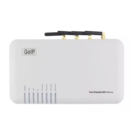
1 x Ethernet CAT5 Cable (2M) 1.6 LED Indicators LED indicators (shown above for GoIP-8) are used to show the current status of the device. They are often used to determine if the GoIP is working normally or not. Description... -
Page 8: Installation
The power is removed by either disconnecting the power to the GoIP or shutting each GSM module individually via its built-in web interface. 1. SIM card slots are located either at the bottom (for old hardware) or at the back (for new hardware) of the main unit. - Page 9 Please only use the AC/DC adapter provided. Adapter with different rating or vendor may damage the device or affect its performance. 5. The Reset button is recessed inside the GoIP cabinet. You need to use a sharp pointer to access the reset button.
-
Page 10: Configuration
When you connect it to a network with a DHCP host, it will obtain an IP address from the DHCP host automatically. Via the GoIP’s GSM channel(s), there are two ways to find out the IP address that is assigned to this port. -
Page 11: Status
The current VoIP and GSM statuses are listed in the Summary page as shown below (extracted from GoIP-8) . They are very essential to display the operation status of the GoIP in order to determine if it is working properly or not. -
Page 12: General
GoIP User Manual d. DIALING <phone number> - This occurs when the GoIP is dialing out a phone number via the corresponding GSM channel or The DIALING status shows that a number is being dialed out via the corresponding GSM channel or a VoIP line. -
Page 13: Gsm
DNS server may solve the problem. g) VPN Status - This shows the current VPN connection status. It only appears when VPN is enabled. 3. Call Management section summarizes the both GoIP and GSM configurations and their corresponding status. - Page 14 7. Carrier - This shows the name of the current GSM carrier. 8. GSM BSC mode - This shows the current setting for the GSM BSC mode which determines how the GoIP selects a base station. For more information, please refers to the section 3.3.15.
- Page 15 GoIP User Manual 1. Module - The model number of the GSM module. 2. Firmware Ver - The version number of the firmware installed in the module. 3. SIM Number - The GSM number that is assigned to the SIM card. User must enter this number manually.
-
Page 16: Sim Call Forward
GoIP User Manual 3.3 Configuration Click “Configuration” on the left hand column to display the Configuration page and the following submenu. 1. Preference 2. Network 3. Basic VoIP 4. Advance VoIP 5. Media 6. Call Out 7. Call Out Auth. - Page 17 GoIP User Manual 3.3.1Preference The preference page shown above consists of the following system level parameters and options as shown in the table below. Default Value Parameter Description (Preference) English 1. Language This sets the webpage and voice prompts language.
- Page 18 GoIP User Manual 4. Auto-provision The auto provision is optional. When this option is enabled, the device downloads its configuration from the Auto Provision Server at start up or at the time interval specified by the Provision Interval. The configuration file name is <Serial Number>.cfg which is just a text file (not encrypted).
- Page 19 Enabling this feature allows the SIM Cards to be installed in a SIM Bank rather than in the on-board SIM slots. GoIP can either register to a SIM Bank or a SIM Server. Please refer to the SIM Bank User Manual for more information.
- Page 20 GoIP User Manual traffics for the device installed when all lines are used simultaneously. In order to get external network access, the LAN port must be configured according to the network environment to be connected. LAN Port There are 3 access methods available to configure the LAN port.
- Page 21 As more features are added, SIP and H.323 VoIP protocols are supported in two different firmware versions. Except GoIP-1, all other models are now shipped with the SIP protocol firmware as a factory default. H.323 protocol is required, the firmware of the device can be changed to the one that supports H.323 protocol.
- Page 22 GoIP User Manual a) All Routing Prefixes are set - Try to match the number received for making an outgoing call against the Routing Prefix of each channel. If only one match is found, the corresponding channel is used to make the outgoing call.
- Page 23 Prefix is a text string which consists of digits, alphabets, and special characters. The maximum length of the Routing Prefix is 120 characters. 2. Config. By Line (for all models except GoIP-1) Mode This mode is only applicable for multi-line models.
- Page 24 Clicking this button after Line 1 is configured will automatically configure other lines with the Line 1 settings with the changes displayed in the following message box. 3. Config. By Group (for all models except GoIP-1) This mode is basically a combination of Single Server mode and Config. By Line mode.
- Page 25 GoIP User Manual 4. Trunk Gateway Mode (for all models except GoIP-1) This mode offers a seamless interface with the SIP Trunk configuration in a SIP server. In general, SIP registration is not required in this mode; this is an advantage for a SIP system that requires a license per registration.
- Page 26 GoIP User Manual Gateway3) specified and then dial out the call via an Idle channel that is used the least (in terms of the number of calls dialed). The last part of the SIP Trunk Gateway IP addresses can be specified as "X" or "x"...
- Page 27 GoIP User Manual The table below summaries all the parameters defined in this section. Parameter Description Default Value (Advanced VoIP) SIP Listening Port Mode SIP Local port defines the network port number that the device listens for incoming SIP messages. This port number is sent to the SIP Sever/Proxy during SIP registration.
- Page 28 GoIP User Manual receive audio packets. Since it may take a few to over 10 seconds for a ringback tone is returned from the GSM network, the caller may hear a long silent period Call OUT Auth. Mode This setting defines how incoming VoIP calls are authenticated when the device is configured for using SIP registration(s).
- Page 29 Stun Server – An external Stun Server is required. This allows the device to obtain the public IP of the network used. Relay Proxy – This is a proprietary method developed by DBL Technology. DBL’s Relay Proxy server must be used. A free copy of the Relay Proxy can be download from DBL’s website (www.dbltek.com).
- Page 30 GoIP User Manual 3.3.5 http://www.dbltek.com...
- Page 31 GoIP User Manual 3.3.6Media This section allows the user to program various settings for media (voice) transmission and format. Depending on your network environment and condition, you may or may not need to change these settings. Please see the parameter table below for more information.
- Page 32 Stun Server – An external Stun Server is required. This allows the device to obtain the public IP of the network used. Relay Proxy – This is a proprietary method developed by DBL Technology. DBL’s Relay Proxy server must be used. A free copy of the Relay Proxy can be download from DBL’s website (www.dbltek.com).
- Page 33 GoIP User Manual 5. G.729AB ~39K (with Silence Compression and Voice Activity Detection (VAD) 6. G.723.1 5.3K / 6.4K ~26K / 27K Note: Time per packet = 30ms is used for all bandwidth calculations. For more calculations with other conditions, please visit the VoIP Bandwidth Calculator website http://www.bandcalc.com/...
- Page 34 The typical application is to terminate VoIP calls via the GSM network. This setting If this parameter is specified, GoIP dials this phone number via the corresponding GSM channel whenever an incoming VoIP call is received for this line. This is a fixed forwarding method and has the highest priority.
- Page 35 Group mode since SIP registration is required. If this parameter is blank and the Callee Number does not equal to the SIP Number defined for this line, GoIP dials out the Caller Number according to the Dial Plan defined. Forwarding to GSM...
- Page 36 If the Callee Number is 913601234567, the actual number dialed is 8613601234567. Restricted Dial Plan This option forces the GoIP to only dial out the phone numbers that match the rules defined in the dial plan. Sleep Interval in between This setting defines an idle interval in between calls.
- Page 37 GoIP User Manual 3.3.9Call IN This page defines how incoming calls to each GSM channel are handled. GSM incoming calls can either be answered and prompted for second dial or forwarded to a phone extension or IVR in the VoIP network connected.
- Page 38 It could be an extension number or an E.164 number. Example: 98765432>108|>101| In this example, GoIP first try to match the incoming GSM caller ID with the number 98765432. If it is a match, GoIP dial the number 108. If the first rule does not match, it will continue to the second rule.
- Page 39 GSM call via GSM call forwarding. Please note that each GoIP cannot have more than one Host channel assigned. Sharing of GSM channels between two Hunt Groups is supported.
-
Page 40: Call In Auth
Setting this parameter enables Hunt Group Sharing feature. This parameter must set the IP of the GoIP which contains the Host channel of the other Hunt Group. Client- This assigns the selected channel to be a client in Hunt Group mode. -
Page 41: Sim
GoIP User Manual Whitelist + Password – Both Whitelist and password are used to authenticate incoming GSM calls. Blacklist – Calls with caller IDs that are listed on the Blacklist are not answered by the channel selected. Whitelist / Blacklist Call screen list can be set to Whitelist or Blacklist. - Page 42 GoIP User Manual The parameters for this section are described in details in the table below. Parameter Description Default Value (SIM Card) 1. GPRS Registration This enables the GPRS registration mode for all GSM channels. Enable 2. SIP Registration when...
-
Page 43: Sim Forward
GoIP User Manual 10. Billing Increment (s) This is a call duration measurement unit expressed in seconds. Depending on your service provider, some services are measured and billed in sixty second increments (one minute) or the billing increment may be in durations of six or even ten seconds. -
Page 44: Imei
GoIP User Manual 1. Unconditional Call Forward all incoming calls unconditionally to the number specified. Not Set Forward Forward Num This specifies the phone number to receive forwarded calls under this condition. 2. Call Forward Busy Forward calls when the GSM Channel is in use. -
Page 45: Sms
GoIP User Manual 3.3.14 SMS This page covers parameters that are related to SMS. The top parameter (SMS to VoIP) is a general setting for all channels. This defines how received SMS messages are used for Call Back or Forward functions which are described in details in the table below. - Page 46 Once the SMS Server is installed and in operation. The following parameters are require to enable the GoIP to register to the SMS Server. Please note that each channel must be programmed individually in order to register to the SMS Server.
-
Page 47: Gsm Carrier
GSM service provider based on the default preference set by the SIM card . When a GoIP is installed at a location that is close to a country border, it is possible that the default service provider is not selected based on the base station signal strength. - Page 48 GoIP User Manual Three modes for base station selection are available: 1. Auto - This mode uses the default GSM base selection mechanism. 2. Poll - This mode limits the number and the list of base stations (BTS) that could be selected.
-
Page 49: Tools
GoIP User Manual 3.4 Tools Click “Tools” on the left hand menu to access the submenu as shown below. Please note the available options under the Tools menu. 3.4.1Online Upgrade Click [Online Upgrade] to upgrade the device firmware. The current version is displayed as well as the last upgrade time. -
Page 50: Change Password
GoIP User Manual Contact us or your local agent/supplier for the latest firmware version. Enter the firmware link (URL) and then click “Start” to begin firmware upgrade. Once the firmware upgrade is completed, the device will reboots itself automatically. Please wait patiently as this process may take a few minutes. -
Page 51: Send Sms
GoIP User Manual The procedures to send an USSD command are: a) Select the Line (GSM channel) that you want to send an USSD command to the service provider. The line status and the SIM (GSM) number are displayed. The last option "All Lines" means that all channels are selected and the same USSD command is sent via all channels provided that they are in the Login Status. -
Page 52: Sms In Box
GoIP User Manual The procedures to send a SMS are: Select the Line (GSM channel) that you want to send a SMS. The line status and the SIM (GSM) number are displayed. The last option "All Lines" means that all channels are selected and the same SMS is sent via all channels provided that they are in the Login Status. -
Page 53: Backup / Restore
GoIP User Manual 3.4.7Backup / Restore The device configuration can be backup or restore via this page. Click [Backup / Resotre Confguration] to access the page shown below. To backup the device configuration, just click [Save] in the Backup Configuration section. -
Page 54: Reboot
GoIP User Manual 3.4.9 Reboot Click [Reboot] to restart the device. Click [OK] in the pop up window shown below to confirm this action. The reboot process will take couple of mins. http://www.dbltek.com... -
Page 55: Appendix A. Special Sms Commands
GoIP User Manual Appendix A. Special SMS Commands In order to manage the device, special SMS commands can be sent to anyone of the GSM channel in order to read the LAN IP, reset the device and reboot the device. The table below summarizes the SMS command syntax. -
Page 56: Appendix B. Sms To Voip
GoIP User Manual Appendix B. SMS To VoIP The device receives SMS messages from both GSM and VoIP networks and they are handled according to the modes defined below. 1. Call Function – In this mode, a received SMS is used to implement the “Call Back” function. The concept is to establish a phone call between the called party and the calling party. - Page 57 GoIP User Manual the Call OUT via GSM parameter of the device must be enabled and the Forward Number associated with this parameter is set to the phone number of the SMS sender. To achieve the Call Back function, the SIP server calls the called party via its phone network and then calls the SIP number.
- Page 58 GoIP User Manual Allow: INVITE, ACK, BYE, CANCEL, OPTIONS, NOTIFY, REFER, REGISTER, MESSAGE, INFO, SUBSCRIBE Content-Type: application/sdp Content-Length: 226 2. Forward Function – This mode supports SMS forwarding from GSM to SIP and from SIP to GSM. Received GSM SMS messages are forwarded to both SIP and GSM depending on the settings of the SMS Forward Number and SMS Forward GSM Number.
- Page 59 GoIP User Manual format. The first line must contain a valid GSM number and then the text message begins at the second line and must meet the restrictions imposed by a normal GSM SMS. A sample of a SIP MESSAGE sent from SIP device is shown below.
-
Page 60: Appendix C. Custom Network Tones
GoIP User Manual Appendix C. Custom Network Tones This section describes how to define custom network tones. The “Custom” selection allows the following tones to be defined as shown on the right. 1. Dial Tone – When an incoming call is answered, this tone is generated to indicate to the caller to dial a number. -
Page 61: Appendix D. Gsm Group Mode
GSM number of the Server channel. The diagram below demonstrates this concept with only single channel GoIPs. In fact, GoIP with multiple channels can also be used. Only one "Server" in a group and all the other channels must be set to "Client" individually. http://www.dbltek.com... -
Page 62: Appendix E. Cid Call Forward
GoIP User Manual Appendix E. CID Call Forward For incoming GSM calls, the phone number of the caller can be displayed at the called party (SIP terminal). The device supports the following two methods. Unfortunately, not all SIP servers support one or both methods. -
Page 63: Appendix F. Volume Adjustment
GoIP User Manual Appendix F. Volume Adjustment The volume adjustment of the device can be accessed via the URL below. http://<device address>/en_US/gaim.html The <device address> is the IP address or domain name of the device. The volume levels of the audio streams from VoIP to GSM and GSM to VoIP are controlled by the input gain and the output gain respectively.
Need help?
Do you have a question about the GoIP and is the answer not in the manual?
Questions and answers