Table of Contents
Advertisement
Advertisement
Table of Contents

Related Manuals for DBL Technology GoIP-1


Summary of Contents for DBL Technology GoIP-1
- Page 1 DBL Technology Co., Ltd. GoIP User Manual www.dbltek.com Technical Support: support@dbltek.com GoIP User Manual VoIP GSM Gateways Models: GoIP GoIP-4/4i GoIP-8/8i, WoIP-8 GoIP-16 GoIP-32 Revision: 1.5 2016/6/24 https://arttel.ru/shop/gsm-shlyuzy/gsm-shlyuz-goip-4...
-
Page 2: Table Of Contents
DBL Technology Co., Ltd. GoIP User Manual www.dbltek.com Technical Support: support@dbltek.com Content Summary ............................... 4 Special Notes ..............................4 General ................................. 4 Introduction ............................4 Protocols .............................. 5 Hardware Features ..........................6 Software Features ..........................6 Package Content ..........................6 LED Indicators ............................. - Page 3 DBL Technology Co., Ltd. GoIP User Manual www.dbltek.com Technical Support: support@dbltek.com 5.4.11 Backup / Restore ..........................59 5.4.12 Reset ..............................60 5.4.13 Reboot ..............................60 Appendix A. Special SMS Commands ......................61 Appendix B. SMS To VoIP ..........................62 Appendix C.
-
Page 4: Summary
DBL Technology Co., Ltd. GoIP User Manual www.dbltek.com Technical Support: support@dbltek.com Summary This User Manual now covers the updates made in the following firmware versions. Please upgrade your device firmware in order to be able to use the new features described in this manual. -
Page 5: Protocols
DBL Technology Co., Ltd. GoIP User Manual www.dbltek.com Technical Support: support@dbltek.com Internet / Intranet VoIP GoIP GoIP4 Service GoIP8 Provider Local Local Telephone VoIP GSM Network Network VoIP World Phone Telephone Network Telephone Telephone Cellphone You can now make a call from anywhere in the world via a VoIP network and then terminate the call via a GoIP / WoIP to the local telephone network (PSTN). -
Page 6: Hardware Features
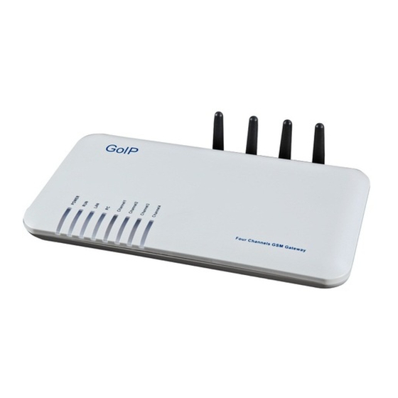
DBL Technology Co., Ltd. GoIP User Manual www.dbltek.com Technical Support: support@dbltek.com Dynamic Host Configuration Protocol (DHCP) Domain Name System (DNS) User Account Authentication (via MD5) Proprietary Relay Protocol (Avoiding VoIP Blockings) 3.3 Hardware Features ... - Page 7 DBL Technology Co., Ltd. GoIP User Manual www.dbltek.com Technical Support: support@dbltek.com Item Appearance Description 1 x Main Unit GoIP (1-Channel) GoIP-4 (4-Channel) GoIP-8 (8-Channel) WoIP-8 (8-Channel) GoIP-16 (16-Channel) GoIP-32 (32-Channel) AC/DC Power Adapter: GoIP1: 12V/500mA https://arttel.ru/shop/gsm-shlyuzy/gsm-shlyuz-goip-4...
-
Page 8: Led Indicators
DBL Technology Co., Ltd. GoIP User Manual www.dbltek.com Technical Support: support@dbltek.com GoIP4: 12V/2A GoIP8: 12V/3A GoIP16: 12V/4A GoIP32: 12V/4.5A 1 x Ethernet CAT5 Cable (2M) 3.6 LED Indicators LED indicators (shown above for GoIP-8) are used to show the current status of the device. They are often used to determine if the device is working normally or not. -
Page 9: Installation
DBL Technology Co., Ltd. GoIP User Manual www.dbltek.com Technical Support: support@dbltek.com Each cellular channel has its own status LED and its color is green. It blinks at a rate of every 100ms (Fast blink) when the corresponding cellular channel is not yet registered to a GSM network. - Page 10 DBL Technology Co., Ltd. GoIP User Manual www.dbltek.com Technical Support: support@dbltek.com For GoIP-16, the SIM card insertion orientation is shown in the figure below. The cut corner is pointing downward with the metal contacts facing the front of the GoIP.
- Page 11 DBL Technology Co., Ltd. GoIP User Manual www.dbltek.com Technical Support: support@dbltek.com 2. The RJ-45 port, labelled “LAN”, is intended for intranet or internet connection. Depending on your network environment, it can be connected various type of network equipment, such as network router, network switch / Hub, xDSL/Cable modem, etc.
-
Page 12: Configuration
DBL Technology Co., Ltd. GoIP User Manual www.dbltek.com Technical Support: support@dbltek.com 5 Configuration The device can be configured via its built-in http web server or via an Auto Provision Server. Auto Provision Server is a free utility supporting both Window and Linux OS. This utility is developed for the sole purpose of automating the configuration of our products. -
Page 13: Status
DBL Technology Co., Ltd. GoIP User Manual www.dbltek.com Technical Support: support@dbltek.com 5.2 Status When you first login to the device webpage, the window below is shown. Please note that there are now 4 new items on the top right hand corner. - Page 14 DBL Technology Co., Ltd. GoIP User Manual www.dbltek.com Technical Support: support@dbltek.com Here are the list of the device parameters shown in this page. CH – This column allows selection of channels for Reset functions. Selection can be done by clicking each box individually or the box for all channels.
-
Page 15: General
DBL Technology Co., Ltd. GoIP User Manual www.dbltek.com Technical Support: support@dbltek.com the Talk Time Limit, the remaining talk time reaches zero. is the icon for resetting the SMS count to zero. is the icon for resetting the ACD and ASR to zero. -
Page 16: Gsm
DBL Technology Co., Ltd. GoIP User Manual www.dbltek.com Technical Support: support@dbltek.com Web Access Records a) Last Client IP – This shows the IP address of the PC for the last web access. b) Last Login Time – The shows the time when the last web access occurred. -
Page 17: Sim Call Forward
DBL Technology Co., Ltd. GoIP User Manual www.dbltek.com Technical Support: support@dbltek.com The top table shows a number of GSM parameters which are useful to determine if the GSM channels in the gateway are working properly. Remote SIM - This tells if Remote SIM function is used or not. "DISABLE" means using the local SIM cards that are inserted to the device. -
Page 18: Configuration
DBL Technology Co., Ltd. GoIP User Manual www.dbltek.com Technical Support: support@dbltek.com 5.3 Configuration Click “Configuration” on the left hand column to display the Configuration page. Under this section, there are 16 items in the submenu as shown below. 5.3.1 Preference... - Page 19 DBL Technology Co., Ltd. GoIP User Manual www.dbltek.com Technical Support: support@dbltek.com The preference page shown above consists of the following system level parameters and options as shown in the table below. Default Value Parameter Description (Preference Page) English 1. Language This sets the webpage and voice prompts language.
- Page 20 DBL Technology Co., Ltd. GoIP User Manual www.dbltek.com Technical Support: support@dbltek.com Access from LAN Enable Set it to “Enable” allows access to the device web via the LAN port. IP Address 1 This specifies the first IP address that is allowed to access the device web. If the device is installed behind a router, you will have to enable DMZ or port forward to the device.
-
Page 21: Network
DBL Technology Co., Ltd. GoIP User Manual www.dbltek.com Technical Support: support@dbltek.com Net Protocol This Specifies the network protocol (UDP or TCP) is used for Remote SIM communications. Encryption Key This specifies the encryption key used for the SIM data communications between the SIM Server and the GoIP. - Page 22 DBL Technology Co., Ltd. GoIP User Manual www.dbltek.com Technical Support: support@dbltek.com to be connected. LAN Port There are 3 access methods available to configure the LAN port. 1. Static IP – This mode applies to both public and private IP network environment. In the LAN port configuration shown on the left, select “Static IP”...
-
Page 23: Basic Voip
As more features are added, SIP and H.323 VoIP protocols are supported in two different firmware versions. Except GoIP-1, all other models are now shipped with the SIP protocol firmware as a factory default. If H.323 protocol is required, the firmware of the device can be changed to the one that supports H.323 protocol. - Page 24 DBL Technology Co., Ltd. GoIP User Manual www.dbltek.com Technical Support: support@dbltek.com 1. Single Server Mode In this mode, only one SIP registration is used for single or multiple-line operation. Please make sure that your SIP server supports multiple-line operation and the SIP account is configured in the SIP server to match the number of lines available in the device.
- Page 25 Prefix is a text string which consists of digits, alphabets, and special characters. The maximum length of the Routing Prefix is 120 characters. 2. Config. By Line (for all models except GoIP-1) Mode This mode is only applicable for multi-line models.
- Page 26 Line 1 settings with the changes displayed in the following message box. 3. Config. By Group (for all models except GoIP-1) This mode is basically a combination of Single Server mode and Config. By Line mode. It allows lines to be split up into groups.
- Page 27 DBL Technology Co., Ltd. GoIP User Manual www.dbltek.com Technical Support: support@dbltek.com 4. Trunk Gateway Mode This mode offers a seamless interface with the SIP Trunk configuration in a SIP server. In general, SIP registration is not required in this mode. Using the Trunk Gateway mode is an advantage on saving a SIP license if your SIP server requires a license per SIP registration.
- Page 28 DBL Technology Co., Ltd. GoIP User Manual www.dbltek.com Technical Support: support@dbltek.com Example: SIP Trunk Gateway2 = 123.124.125.x This example shows that Calls originated from 123.124.125.0 to 123.124.125.255 are accepted. Call routing to a GSM channel is now based on the Routing Prefix of each GSM channel (Line x). The channel selection algorithm is the same as the one described in the Single Server Mode.
-
Page 29: Advanced Voip
DBL Technology Co., Ltd. GoIP User Manual www.dbltek.com Technical Support: support@dbltek.com 5.3.4 Advanced VoIP The parameters in the Advance VoIP section are common for all configuration modes. In general, these parameters are preconfigured with factory defaults. Users should only modify the parameters required. - Page 30 DBL Technology Co., Ltd. GoIP User Manual www.dbltek.com Technical Support: support@dbltek.com media (before the call is answered). This allows to the caller to hear the ringback from the GSM network. This is done in order to avoid a long silent period before a ringback tone is returned from the GSM network.
- Page 31 DBL Technology Co., Ltd. GoIP User Manual www.dbltek.com Technical Support: support@dbltek.com Signaling NAT Traversal This setting is not required if the target SIP server / PBX supports NAT traversal. None However, if your ISP blocks VoIP traffics, you could try to use Relay Proxy setting.
-
Page 32: Media
DBL Technology Co., Ltd. GoIP User Manual www.dbltek.com Technical Support: support@dbltek.com 5.3.5 Media This section allows the user to program various settings for media (voice) transmission and format. Depending on your network environment and condition, you may or may not need to change these settings. - Page 33 DBL Technology Co., Ltd. GoIP User Manual www.dbltek.com Technical Support: support@dbltek.com Parameters Description Default Value (Media) RTP Port Range This specifies the range of RTP port to be used for audio stream. 16384 - 32768 Packet length (ms) This specifies the length (in time) of each packet. However, the packet length is codec dependent as well.
-
Page 34: Call Out
DBL Technology Co., Ltd. GoIP User Manual www.dbltek.com Technical Support: support@dbltek.com Audio Codec Preference Six types of audio codec are supported and they are summarized in the table below. All codecs are enabled in the Codec Raw Data Ethernet 802.3... - Page 35 DBL Technology Co., Ltd. GoIP User Manual www.dbltek.com Technical Support: support@dbltek.com The parameters available in this section are described in details in the table below. Parameter Description Default Value GSM Auto Redial This is a general parameter for all channels. It enables a call to be redialed automatically in Enabled x seconds after the last attempt fails.
- Page 36 DBL Technology Co., Ltd. GoIP User Manual www.dbltek.com Technical Support: support@dbltek.com line, a second dial tone is generated to wait the caller to dial a phone number. Please note that this could only happen in the Single Server mode, Config by Line mode, and Config by Group mode since SIP registration is required.
-
Page 37: Call Out Auth
DBL Technology Co., Ltd. GoIP User Manual www.dbltek.com Technical Support: support@dbltek.com Example: Dial Plan: 8613[5-9]XXXXXXXX:-86+0| This rule performs the following actions: 1. Phone number must be 13-digit long. 2. Phone number must start with 86135, 86136, 86137, 86138, 86139. -
Page 38: Call In
DBL Technology Co., Ltd. GoIP User Manual www.dbltek.com Technical Support: support@dbltek.com Remark: Adding a "#" digit in front of a Whitelist entry enables a special call back function. When the caller ID of an incoming call is matched, the device first drops the call and then call back the caller automatically to allow the caller to dial a phone number. - Page 39 DBL Technology Co., Ltd. GoIP User Manual www.dbltek.com Technical Support: support@dbltek.com Disabled – Incoming GSM caller ID is not transmitted to SIP. Use Remote Party ID – This enables the Remote-Party-ID field is sent as part of the INVITE message.
- Page 40 DBL Technology Co., Ltd. GoIP User Manual www.dbltek.com Technical Support: support@dbltek.com be adopted is limited by this length. Each rule must end with the “|” character. When there is no match, the incoming GSM call is handled as if the Forward Number is blank.
-
Page 41: Call In Auth
DBL Technology Co., Ltd. GoIP User Manual www.dbltek.com Technical Support: support@dbltek.com Host Address The Host Address field specifies the IP address of the device that contains the Host channel. If a Client and its Host belong to the same device, its device IP is entered in this parameter. -
Page 42: Sim
DBL Technology Co., Ltd. GoIP User Manual www.dbltek.com Technical Support: support@dbltek.com This setting specifies the Call Forward method when the GSM channel is configured as the server in HUNT Group mode. 1. Unconditional Call Forward – Incoming calls are always forwarded to an idle channel. - Page 43 DBL Technology Co., Ltd. GoIP User Manual www.dbltek.com Technical Support: support@dbltek.com 7. Talk Time Limit (m) There are 3 ways to define the Talk Time Limit for a SIM card. 1. Total talk time allowed without any time limit When the accumulative talk time of a channel reaches this limit, the corresponding SIM card is disabled.
-
Page 44: Sim Forward
DBL Technology Co., Ltd. GoIP User Manual www.dbltek.com Technical Support: support@dbltek.com 12. SMS Alert ID This parameter is used to identify the channel sending the SMS Alert. 13. SMS Alert Trigger The Remain Time is the Total Talk Time Limit minus the total talk time used. -
Page 45: Imei
DBL Technology Co., Ltd. GoIP User Manual www.dbltek.com Technical Support: support@dbltek.com 4. Call Forward Forward calls when the GSM channel cannot register to the carrier. Not Set Unreachable Forward Num This specifies the phone number to receive forwarded calls under this condition. -
Page 46: Sms
DBL Technology Co., Ltd. GoIP User Manual www.dbltek.com Technical Support: support@dbltek.com The IMEI of each channel can be programmed manually. An exact 15-digit number must be entered; otherwise, the number entered is ignored and the old IMEI will still be used. The device calculates the check digit and then replace the last digit. - Page 47 DBL Technology Co., Ltd. GoIP User Manual www.dbltek.com Technical Support: support@dbltek.com Parameter Description Default Value This parameter applies to ALL channels. SMS to VoIP Disabled This defines how the device handles received SMS messages. 1. Call Function – This mode is used to support Call Back function via incoming GSM messages.
- Page 48 DBL Technology Co., Ltd. GoIP User Manual www.dbltek.com Technical Support: support@dbltek.com The parameters defined below are channel dependent. Please make sure that the desired channel ) is selected before making changes. Parameter (SMS) Description Default Value 1. SMS Server SMS Server is a Linux based utility which is used to manage GoIPs registered to send and receive SMS messages.
-
Page 49: Gsm Carrier
DBL Technology Co., Ltd. GoIP User Manual www.dbltek.com Technical Support: support@dbltek.com 7. SMS to Email This enables the forwarding of SMS received via the channel selected to a designated email address. Outgoing Email Server This specifies the SMTP Server for sending emails. - Page 50 DBL Technology Co., Ltd. GoIP User Manual www.dbltek.com Technical Support: support@dbltek.com Three modes for base station selection are available: 1. Auto - This mode uses the default GSM base station selection mechanism. Use this default setting if you don’t have any preference.
-
Page 51: Event Trigger
DBL Technology Co., Ltd. GoIP User Manual www.dbltek.com Technical Support: support@dbltek.com 4. Whitelist/Blackllist Whitelist defines the base stations that are going to be used. Blacklist defines the base stations that are NOT going to be used. 3. Fixed - This mode locks the base station to the Cell ID specified. First Press to get the current list of base stations detected. - Page 52 DBL Technology Co., Ltd. GoIP User Manual www.dbltek.com Technical Support: support@dbltek.com blocked or does not have enough balance. 6. # of consecutive VoIP calls (duration < (s)) > xxx – This event monitors the call duration of consecutive calls. When you have short durations of consecutive calls, it could be an indication that the SIM card is blocked or does not have enough balance.
-
Page 53: Tools
DBL Technology Co., Ltd. GoIP User Manual www.dbltek.com Technical Support: support@dbltek.com 5.4 Tools Click “Tools” on the left hand menu to access the submenu as shown below. Please note the available options under the Tools menu. 5.4.1 Online Upgrade Click [Online Upgrade] to upgrade the device firmware. -
Page 54: Send Ussd
DBL Technology Co., Ltd. GoIP User Manual www.dbltek.com Technical Support: support@dbltek.com 5.4.3 Send USSD Click [Send USSD] to access the webpage (as shown below) to send USSD commands. The procedures to send an USSD command are: a) Select the Line (GSM channel) that you want to send an USSD command to the service provider. The line status and the SIM (GSM) number are displayed. -
Page 55: Send Sms
DBL Technology Co., Ltd. GoIP User Manual www.dbltek.com Technical Support: support@dbltek.com Click [Back] to return to the Send USSD command page. For certain service requests, user responses are required. Just following USSD message and then send back a response via SEND USSD command. -
Page 56: Sms Outbox
DBL Technology Co., Ltd. GoIP User Manual www.dbltek.com Technical Support: support@dbltek.com SMS OutBox 5.4.6 Click [SMS OutBox] to view the last 10 SMS message sent as shown below. Press at the end of each message to delete the message. Press to delete all message for the selected line. -
Page 57: Dial Test
DBL Technology Co., Ltd. GoIP User Manual www.dbltek.com Technical Support: support@dbltek.com 2. Specify the number of ping messages to be sent in the “Ping Count” field. 3. Press to start the Ping Test. The test results are then displayed in the window below. - Page 58 DBL Technology Co., Ltd. GoIP User Manual www.dbltek.com Technical Support: support@dbltek.com USSD Method: Select the Line that is linked to the SIM card that you want to retrieve its phone number. Set Method = USSD Enter the USSD Command as required by your Carrier.
-
Page 59: Backup / Restore
DBL Technology Co., Ltd. GoIP User Manual www.dbltek.com Technical Support: support@dbltek.com this parameter is enable, GoIP will check the content of each SMS. If the content matches the Trigger String for an SMS Reply, GoIP then creates a message with the content equals to Reply Content + the SIM card phone number of the sender. -
Page 60: Reset
DBL Technology Co., Ltd. GoIP User Manual www.dbltek.com Technical Support: support@dbltek.com 5.4.12 Reset Click [Reset] to reset the device configuration back to the factory default. Click [OK] in the pop up window shown below to confirm this action. Click [OK] to reset the device configuration back to the factory default! 5.4.13 Reboot... -
Page 61: Appendix A. Special Sms Commands
DBL Technology Co., Ltd. GoIP User Manual www.dbltek.com Technical Support: support@dbltek.com Appendix A. Special SMS Commands In order to manage the device, special SMS commands can be sent to anyone of the GSM channel in order to read the LAN IP, reset the device and reboot the device. The table below summarizes the SMS command syntax. -
Page 62: Appendix B. Sms To Voip
DBL Technology Co., Ltd. GoIP User Manual www.dbltek.com Technical Support: support@dbltek.com Appendix B. SMS To VoIP The device receives SMS messages from both GSM and VoIP networks and they are handled according to the modes defined below. 1. Call Function – In this mode, a received SMS is used to implement the “Call Back” function. The concept is to establish a phone call between the called party and the calling party. - Page 63 DBL Technology Co., Ltd. GoIP User Manual www.dbltek.com Technical Support: support@dbltek.com To achieve the Call Back function, the SIP server calls the called party via its phone network and then calls the SIP number. Since a call to this SIP number is set to forward to the phone number of the SMS sender, both the called and calling parties can then be connected.
- Page 64 DBL Technology Co., Ltd. GoIP User Manual www.dbltek.com Technical Support: support@dbltek.com 2. Forward Function – This mode supports SMS forwarding from GSM to SIP and from SIP to GSM. Received GSM SMS messages are forwarded to both SIP and GSM depending on the settings of the SMS Forward Number and SMS Forward GSM Number.
- Page 65 DBL Technology Co., Ltd. GoIP User Manual www.dbltek.com Technical Support: support@dbltek.com 2001. SIP SMS Sender = 3999 SIP SMS Recipient = 2001 SIP SMS Content = 13682626800 Hello world SIP MESSAGE Sent from the SIP Server: MESSAGE sip:20001@192.168.2.162:5060 SIP/2.0 From: <sip:3999@192.168.2.89>;tag=5031...
-
Page 66: Appendix C. Custom Network Tones
DBL Technology Co., Ltd. GoIP User Manual www.dbltek.com Technical Support: support@dbltek.com Appendix C. Custom Network Tones This section describes how to define custom network tones. The “Custom” selection allows the following tones to be defined as shown on the right. -
Page 67: Appendix D. Gsm Group Mode
DBL Technology Co., Ltd. GoIP User Manual www.dbltek.com Technical Support: support@dbltek.com Appendix D. GSM Group Mode The GSM Group mode is designed to simulate the function of one GSM number with multiple lines. The idea is to form a GSM group with one number being the "Server". Only this GSM number is announced to the public. -
Page 68: Appendix E. Cid Call Forward
DBL Technology Co., Ltd. GoIP User Manual www.dbltek.com Technical Support: support@dbltek.com Appendix E. CID Call Forward For incoming GSM calls, the phone number of the caller can be displayed at the called party (SIP terminal). The device supports the following two methods. -
Page 69: Appendix F. Volume Adjustment
DBL Technology Co., Ltd. GoIP User Manual www.dbltek.com Technical Support: support@dbltek.com Appendix F. Volume Adjustment The volume adjustment of the device can be accessed via the URL below. http://<device address>/en_US/gaim.html The <device address> is the IP address or domain name of the device. The volume levels of the audio streams from VoIP to GSM and GSM to VoIP are controlled by the input gain and the output gain respectively.
Need help?
Do you have a question about the GoIP-1 and is the answer not in the manual?
Questions and answers
MY GSM DOES NOT DETECT SIMCARDS IN SOME OF ITS PORTS BUT THE SAME SIM CARD WAS WORKING IN ONE OF THE PORTS BUT AFTER REPLACING IT TO OTHER PORTS IT INDICATES GSM "N"
The DBL Technology GoIP-1 may not detect SIM cards in some ports due to the following reasons:
1. The SIM card is not inserted properly.
2. The SIM card is damaged.
3. Incorrect SIM card orientation.
4. Issues with the SIM Bank or SIM Server configuration when using the Remote SIM function.
5. Bad network conditions.
6. Improper network configuration.
This answer is automatically generated