Sign In
Upload
Manuals
Brands
Image Access Manuals
Scanner
bookeye 3
Image Access bookeye 3 Manuals
Manuals and User Guides for Image Access bookeye 3. We have
2
Image Access bookeye 3 manuals available for free PDF download: Assembly Manual, Operation Manual
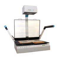
Image Access bookeye 3 Assembly Manual (79 pages)
Version R1
Brand:
Image Access
| Category:
Scanner
| Size: 3 MB
Table of Contents
Table of Contents, Part
2
Table of Contents
6
Table of Pictures
12
A Hardware Setup
12
Content on Delivery
12
Picture 1: Transport Box
12
Picture 2: Cardboard Separator with Lamps and Neck
13
Picture 3: Reference Folder Removed
13
Picture 4: Scanner Main Body and Camera Head Box
14
Picture 5: Camera Head in Cardboard Box
14
Tools and Assembling Material
15
Device Location
16
Environment
16
Ambient Light
16
A.1.2 Device Location
16
Scanner Table
17
Power Outlet
17
A.1.2.3 Scanner Table
17
Assembling the Components
18
Assembling the Camera Head to the Neck
18
Picture 6: Attaching Camera Neck to Camera Head
18
Picture 7: Check the Alignment
19
Picture 8
19
Picture 9: Fastening at Position a
19
Picture 10: Fastening at Position B
19
Picture 11: Camera Neck Assembled at Camera Head
20
Picture 12: Placing the Cover on the Neck
20
Picture 13: Cover in Final Position
20
Picture 14: Fastening the Screws
20
Assembling Lamps and Camera to the Body Element
21
Picture 15: Two Persons(!) Lift the Device out of the Transport Box
21
Picture 16: Removing the Transport Screws
22
Picture 17: Removing the Countersunk Socket Screw
22
Picture 18: Remove Marked Screws
23
Picture 19: Body Element Cover Opened
23
Picture 20: Position of Gas Spring Fixture at Right Lamp
24
Picture 21: Fixing the Lamp
24
Picture 22: Camera Neck Assembly
25
Picture 23: Front Side
25
Picture 24: Back Side
25
Picture 25: Connector Board with Camera Neck Cables
26
Picture 26: Connector of Flat Ribbon Cable
26
Picture 27: Cable Loop
26
Picture 28: Keyboard Cable While Moving the Body Cover
27
Picture 29: Body Cover at Edge of Power Supply
27
Assembling the Glass Plate
28
Picture 30: Book Cradle Controller
28
Picture 31: Bearing in the Center of the Glass Plate
28
Picture 32: T-Slot Nut in Corresponding Position
29
Picture 33: Hinge Mounted at Right Lamp
29
Picture 34: Position of Locking Springs
30
Picture 35: Removing the Locking Spring
30
Picture 36: Gas Spring Mounted to Glass Plate
31
Picture 37: Locking Spring Inserted
31
Picture 38: Locking Spring Locked
31
Picture 39: Gas Spring Completely Mounted
32
Setting the Initial Lamp Position
33
Performing the Mechanical Adjustment of the Lamps
34
Picture 40: Press the Keys Simultaneously
34
Table of Pictures, Part 2
35
Picture 41: Lamps in Start Position
35
Picture 42: Up/Down Key on Right Side of Keyboard
35
Picture 43: Light Beam on Right Side of the Book Cradle
36
Saving the Lamp Positions
37
Leaving the Initialization Mode Without Saving
37
Picture 44: Light Beam Adjusted
37
Lamp Position Control Mode
38
B Software Setup
39
Setup Network IP Address
39
Picture 45: Start Screen
39
Picture 46: Login Level Screen
40
Picture 47: Poweruser Main Menu Screen
40
Picture 48: Network Configuration Screen
41
Mandatory Optical Adjustments
42
Picture 49: Scan2Net Start Screen
43
Picture 50: Buttons for Login Levels
43
Picture 51: Poweruser Main Menu Screen
44
Picture 52: Adjustment & Support Screen
44
Scan Start
45
Picture 53: Scan Start Adjust Screen
45
B.2.1 Scan Start
45
Picture 54: Scan Start Results
46
Auto Focus
47
Picture 55: Available Glass Plate Positions
47
B.2.2 Auto Focus
47
Auto Focus Measurement with Glass Plate Opened
48
Picture 56: Auto Focus Measurement with Open Glass Plate
48
Picture 57: Auto Focus Results
49
Auto Focus Measurement with Glass Plate Closed
50
Picture 58: Information about Book Cradles Position
50
B.2.2.2 Auto Focus Measurement with Glass Plate Closed
50
Picture 59: Auto Focus Measurement Screen
51
Scan Center
52
Picture 60: Scan Center Screen
52
B.2.3 Scan Center
52
Some Basic Information
53
White Balance
53
Picture 61: Brightness Correction Factor Screen
54
Picture 62: R G B Controls
54
White Balance with Glass Plate Opened
55
Picture 63: Glass Plate Positions for White Balance
55
B.2.4.2 White Balance with Glass Plate Opened
55
Picture 64: White Balance Screen, Glass Plate Opened
56
White Balance with Glass Plate Closed
57
Picture 65: White Balance Screen, Glass Plate Closed
57
Laser Check
58
Picture 66: Laser Check Screen
58
B.2.5 Laser Check
58
Picture 67: Laser Check Result
59
Options and Settings
60
Time Server
60
Picture 68: Adjust Time & Date Screen
60
B.3 Options and Settings
60
Sound Control
61
Picture 69: S2N Sound System Screen
61
Picture 70: Link Sounds to Events Screen
61
B.3.2 Sound Control
61
Firmware Update
62
Picture 71: Update Scanner Firmware Screen
62
B.3.3 Firmware Update
62
Install Options
63
Picture 72: Install Option Screen
63
B.3.4 Install Options
63
Install ICC Profiles
64
Picture 73: ICC Profile Screen
64
B.3.5 Install ICC Profiles
64
Picture 74: Perform Speed Test Screen
65
C Tests and Troubleshooting
65
Picture 75: Network Analyzer Parameters Screen
66
Picture 76: Network Analyzer Result Screen
66
Picture 77: Scan Test Target Screen
67
Picture 78: CSTT Test Target Screen
67
C.2 Scan Test Targets
67
Picture 79: Scan Test Target Screen
68
Picture 80: IT8 Test Target Screen
68
C.2.2 Scan IT8 Test Target
68
Picture 81: Connectors on Rear Panel
69
C.3 Recovery Function
69
C.4 Troubleshooting Matrix
71
C.5 Error Codes
73
D Technical Data
76
D.3 Electrical Specifications
77
D.4 Dimensions and Weight
78
Advertisement
Image Access bookeye 3 Operation Manual (72 pages)
version R2
Brand:
Image Access
| Category:
Scanner
| Size: 5 MB
Table of Contents
Table of Contents, Part
2
Introduction
3
General Information about Manuals
4
Version History
5
Table of Contents
6
A Hardware Operation
11
Safety Notes
11
Marking of Safety Notes
11
Laser Safety Note
11
Device Overview
12
Picture 1: Components of Bookeye® 3 Scanner
12
A.2 Device Overview
12
A.2.1 Device Location
13
Ambient Light
13
Device Location
13
Environment
13
Connectors on the Rear Side
14
Power Outlet
14
Table
14
Picture 2: Bookeye® 3 Scanner Back Side View
14
A.2.1.3 Table
14
Connecting Foot Pedal Switches
15
Connecting the Network
15
Connecting the Power Source
15
Starting the Bookeye® 3 Scanner
16
Picture 3: Display before Power up
16
Stopping the Bookeye® 3 Scanner
17
Book Cradle
18
Removing the Book Cradle Plates
18
Picture 4: Removing a Book Cradle Plate
18
A.4 Book Cradle
18
Book Cradle Control Keys
19
Picture 5: Book Cradle Control Keys
19
Operating the Book Cradle
20
Picture 6: Book Cradle at Start
20
Picture 7: Book Cradle at Start with Glass Plate Option
20
Picture 8: Horizontal Alignment Check
21
Picture 9: Book Cradle in the Middle of the Book
22
B Software Operation
23
The Integrated User Interface
23
Picture 10: Start Screen
23
The Main Screen
24
Picture 11: Main Screen
24
B.1.1 the Main Screen
24
The Options Screen
26
Picture 12: Options Screen
26
B.1.2 the Options Screen
26
Book Fold Options
28
Fixed Focus Mode
28
Picture 13: Book Fold Option Screen
28
Picture 14: Book Fold Option Screen
28
B.1.2.1 Book Fold Options
28
Embedded Meta Data
29
Picture 15: Metadata Screen
29
B.1.2.3 Embedded Meta Data
29
The Properties Screen
30
Picture 16: Properties Screen
30
B.1.3 the Properties Screen
30
Picture 17: X- and y Offset Definition
31
The Camera Screen
32
Picture 18: Camera Screen
32
B.1.4 the Camera Screen
32
Picture 19: DPI Mode Fixed
33
Picture 20: DPI Mode Flexible
34
Picture 21: Black Threshold Slider
35
Picture 22: Gamma Slider with Preselection Buttons
36
Picture 23: Color Gain Screen
36
The Settings Screen
37
Picture 24: Settings Screen
37
Picture 25: List of Available Languages
37
B.1.5 the Settings Screen
37
Table of Pictures, Part 2
38
Picture 26: Skin Selector
38
Picture 27: Tool Tips
38
Picture 28: Status Window
38
The Format Screen
39
Picture 29: Format Screen
39
B.1.6 the Format Screen
39
Picture 30: Rectangle Dragged with Mouse
40
Picture 31: "Zoom In" Result
40
Output Options
41
Picture 32:Output Option Show
41
Picture 33: Output Options in Scan Window
41
B.1.7 Output Options
41
Output Option Save
42
Picture 34: Image Output Option
42
Picture 35: Metadata Mask
42
B.1.7.1 Output Option Save
42
Output Option Print
43
Picture 36: Output Option Print
43
Picture 37: Available List of Printers for Option Print
43
Output Option Copy
44
Picture 38: Output Option Copy
44
Output Option FTP Upload
46
Picture 39: Output Option FTP Upload
46
Output Option Mail
48
Picture 40: Output Option Mail
48
Output Option Network
50
Picture 41: Output Option Network
50
The Setup Screen
51
Picture 42: Login Screen
51
B.2 the Setup Screen
51
USER Login Level
52
Picture 43: User Screen
52
B.2.1 USER Login Level
52
Device Info
53
Picture 44: Device Info Screen
53
B.2.1.1 Device Info
53
Operation Info
54
Picture 45: Operation Info Screen
54
B.2.1.2 Operation Info
54
User Settings
55
Picture 46: User Settings Screen
55
B.2.1.3 User Settings
55
Picture 47: Volume Level
56
Picture 48: Foot Pedal Settings
57
Picture 49: Splitting Start Page
58
Laser Guided Document Type Detection
59
Description of the Laser Purposes
59
Picture 50: Correct Versa Incorrect Placement
59
B.3 Laser Guided Document Type Detection
59
Picture 51: Holding down a Book
60
Scanning in Fixed Focus Mode
61
Scanning in Flat Mode
61
Scanning in Folder Mode
62
Picture 52: Scanning in Folder Mode
62
Scanning in Book Mode
63
C Tests and Troubleshooting
64
D Technical Data
66
D.3 Electrical Specifications
67
D.4 Dimensions and Weight
68
D.5 FCC Declaration of Conformity
69
D.6 CE Declaration of Conformity
70
Advertisement
Related Products
Image Access WideTEK 36
Image Access WideTEK 36 DS
Image Access WideTek 36C
Image Access WideTEK 36CL
Image Access WideTEK 36ART
Image Access WideTEK 36CL-600
Image Access WideTEK 36ART-600
Image Access Bookeye 4
Image Access Bookeye 4 V1A Professional
Image Access Bookeye Color
Image Access Categories
Scanner
Printer
Monitor
Racks & Stands
Scanners
More Image Access Manuals
Login
Sign In
OR
Sign in with Facebook
Sign in with Google
Upload manual
Upload from disk
Upload from URL