
Subscribe to Our Youtube Channel
Related Manuals for Jungheinrich DFG 660

Summary of Contents for Jungheinrich DFG 660
- Page 1 DFG/TFG 660-690 02.11 - Operating instructions 51139143 02.11 DFG 660 DFG 670 DFG 680 DFG 690 DFG S80 DFG S90 TFG 660 TFG 670 TFG 680 TFG 690 TFG S80 TFG S90...
- Page 2 Declaration of Conformity Jungheinrich AG, Am Stadtrand 35, D-22047 Hamburg Manufacturer or agent acting in the European Union Type Option Serial no. Year of manufacture DFG 660 DFG 670 DFG 680 DFG 690 DFG S80 DFG S90 TFG 660 TFG 670...
- Page 4 Our trucks are subject to ongoing development. Jungheinrich reserves the right to alter the design, equipment and technical features of the system. No guarantee of particular features of the truck should therefore be assumed from the present operating instructions.
- Page 5 Jungheinrich Aktiengesellschaft Am Stadtrand 35 22047 Hamburg - Germany Tel: +49 (0) 40/6948-0 www.jungheinrich.com...
-
Page 6: Table Of Contents
Table of Contents Correct Use and Application ............ 11 General....................Correct application................... Approved application conditions.............. Proprietor responsibilities ................ Adding attachments and/or accessories..........Truck Description ..............15 Application ....................Truck models and rated capacity............. Assemblies and Functional Description........... Assembly Overview ................. Functional Description ................ - Page 7 Fuelling the Truck ..............45 General....................Safety regulations for handling diesel fuel and LPG........ LPG system relief valve................Adding diesel ................... Fuelling ....................Fuelling with fuel containers ..............LPG containers..................LPG bottles....................Liquid gas tank ..................Fuel level indicator................... Display unit ....................Operation .................
- Page 8 6.15 Operating additional attachments for the Multi Pilot ........ 120 6.16 Fitting additional attachments..............122 Towing trailers ..................123 Optional equipment ................. 125 Sliding windows ..................125 Emergency Exit ..................126 Driver'S Seat Heater................126 Adjusting the Multifunction Display............127 Fire Extinguisher..................
-
Page 10: A Correct Use And Application
A Correct Use and Application General The industrial truck described in the present operating instructions is designed for lifting, lowering and transporting load units. It must be used, operated and serviced in accordance with the present instructions. Any other type of use is beyond the scope of application and can result in damage to personnel, the industrial truck or property. -
Page 11: Approved Application Conditions
Approved application conditions DANGER! Do not exceed the permissible surface and spot load limits on the travel routes. At blind spots get a second person to assist. The driver must ensure that the loading dock / ramp cannot move or come loose during loading / unloading. -
Page 12: Proprietor Responsibilities
Proprietor responsibilities For the purposes of the present operating instructions the “proprietor” is defined as any natural or legal person who either uses the industrial truck himself, or on whose behalf it is used. In special cases (e.g. leasing or renting) the proprietor is considered the person who, in accordance with existing contractual agreements between the owner and user of the industrial truck, is charged with operational duties. -
Page 14: B Truck Description
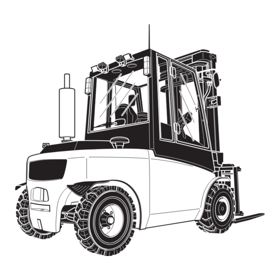
B Truck Description Application The DFG/TFG 660-690 is a four-wheel IC engine sit-down forklift truck. The DFG series are diesel engine trucks, while the TFG series are fitted with a petrol engine for LPG operation. The DFG/TFG 660-690 is a cantilever counterbalanced truck which can lift, transport and deposit loads using the load handler attached in front. -
Page 15: Assemblies And Functional Description
Assemblies and Functional Description Assembly Overview Item Description Item Description 1 o Fork adjustment 8 t Exhaust pipe 2 t Load chains 9 t Steer axle 3 t Mast 10 t Counterweight 4 t Steering column 11 t Illumination 5 t Cab 12 t Drive 6 t Driver's seat 13 t Fork carriage... -
Page 16: Functional Description
Functional Description Chassis and superstructure A rigid chassis which protects the units and controls, provides the truck with maximum static safety. A wide opening cab (5) facilitates service and maintenance work. The hydraulic oil reservoir is integrated on the right-hand side and the fuel tank on the opposite side of the chassis. - Page 17 Drive system A power shift gear with radiator and torque converter is directly flanged to the engine. This transfers the force to the drive axle (12). The travel direction lever on the steering column, on the multi-task lever or on the pedal controller (o) controls forward/reverse travel and the neutral position.
-
Page 18: Technical Specifications
Values indicated with *) may vary, depending on the types of equipment used (e.g. mast, cabin, tyres etc.). Technical data specified in accordance with VDI 2198. Technical modifications and additions reserved. Performance data DFG 660-690 Description Capacity 6000 7000 8000... - Page 19 DFG S80-S90 Description Capacity 8000 9000 Load centre distance Travel speed* with / 22.3/22.6 22.3/22.6 km/h without load Lift speed with / without 0.40/0.60 0.40/0.60 load Lowering speed with / 0.60/0.36 0.60/0.36 without load Gradeability 21.5/25.0 20.9/24.0 with / without load Tow force 49.5/49.5 52.9/52.9...
- Page 20 TFG 660-690 Description Capacity 6000 7000 8000 9000 Load centre distance Travel speed* with / 22.4/22.6 22.4/22.6 22.4/22.6 22.4/22.6 km/h without load Lift speed with / without 0.40/0.48 0.40/0.48 0.40/0.48 0.40/0.48 load Lowering speed with / 0.60/0.48 0.60/0.36 0.60/0.36 0.60/0.36 without load Gradeability 27.5/30.0...
- Page 21 TFG S80-S90 Description Capacity 8000 9000 Load centre distance Travel speed* with / 22.4/22.6 22.4/22.6 km/h without load Lift speed with / without 0.40/0.48 0.40/0.48 load Lowering speed with / 0.60/0.36 0.60/0.36 without load Gradeability* 20.2/23.0 17.6/20.0 with / without load Tow force 45.6/45.6 45.6/45.6...
-
Page 22: Dimensions
Dimensions DFG 660-690 Description a/2 Safety distance Mast height retracted* 2710 2710 3010 3160 Lift* 3600 3600 3600 3600 Mast height extended* 4510 4510 4810 4960 Overhead guard 2705 2705 2705 2705 height* Seat height* 1600 1600 1600 1600 Coupling height Mast tilt, forward* °... - Page 23 DFG S80-S90 Description a/2 Safety distance Mast height retracted* 3160 3310 Lift* 3600 3600 Mast height extended* 4960 5110 Overhead guard 2705 2705 height* Seat height* 1600 1600 Coupling height Mast tilt, forward* ° Mast tilt, back* ° Length, including 5640 5840 forks*...
- Page 24 TFG 660-690 Description Lift* 3600 3600 3600 3600 Mast height extended* 4510 4510 4810 4960 Overhead guard 2705 2705 2705 2705 height* Seat height* 1600 1600 1600 1600 Coupling height Mast tilt, forward* ° Mast tilt, back* ° Length, including 4860 4870 4980...
- Page 25 TFG S80-S90 Description Overhead guard 2705 2720 height* Seat height* 1600 1600 Coupling height Mast tilt, forward* ° Mast tilt, back* ° Length, including 5740 5740 forks* Length, including fork 3940 3940 shank* Overall width* 2150 2150 s/e/l Fork dimensions* 70/180/ 70/180/ 1800...
-
Page 27: Weights
Weights All dimensions in kg. DFG 660-690 Net weight* 10500 10800 11700 12500 Axle load w.o. load front / 5500/5000 5500/5300 6000/5700 6000/6500 rear* Axle load with load front / 14900/1600 16000/1800 17700/2000 19000/2500 rear* *) The data listed in the table corresponds to the standard version. -
Page 28: Mast Versions
Mast versions All dimensions in mm DFG/TFG 660-680 Mast table VDI 3596 Lift h Free lift Retracted height h Extended height h Description 660/670 660/670 3600 2710 3010 4510 4810 4000 2910 3210 4910 5210 4500 3160 3460 5410 5710 5000 3410 3710... - Page 29 DFG/TFG 690-S90 Mast table VDI 3596 Lift h Free lift Retracted height h Extended height h Description 690-S80 690-S80 3600 3160 3310 4960 5110 4000 3360 3510 5360 5510 4500 3610 3760 5860 6010 5000 3860 4010 6360 6510 5500 4110 4260 6860...
-
Page 30: Tyre Type
Tyre type NOTE When replacing tyres/rims fitted at the factory, always use original spare parts or tyres approved by the manufacturer. Otherwise the manufacturer's specification cannot be guaranteed. If you have any queries please contact the manufacturer's customer service department. DFG/TFG 660-690 Description DFG/TFG... -
Page 31: Engine Data
Engine Data DFG 660-680 Description DFG 660 DFG 670 DFG 680 Cylinders/cubic capacity 4/4400 4/4400 4/4400 cm³ Rated speed (without load) 2200 2200 2200 Idle speed Motor output Fuel consumption l/h [kg/h] 60 VDI duty cycles/h DFG 690-S90 Description DFG 690... -
Page 32: En Norms
EN norms Noise emission level – DFG 660-690, S80: 78 dB (A)* – DFG S90: 70 dB (A)* – TFG: 78 dB(A)* *+/- 4 dB(A) depending on the truck's equipment in accordance with EN 12053 as harmonised with ISO 4871. - Page 33 Electromagnetic compatibility (EMC) The manufacturer confirms that the truck adheres to the limits for electromagnetic emissions and resistance as well as the static electricity discharge test in accordance with EN 12895 as well as the standardised instructions contained therein. No changes to electric or electronic components or their arrangement may be made without the written agreement of the manufacturer.
-
Page 34: Conditions Of Use
Conditions of use Ambient temperature – operating at -20 to 40°C Special equipment and authorisation are required if the truck is to be constantly used in conditions of extreme temperature or air humidity fluctuations. Electrical requirements The manufacturer certifies compliance with the requirements for the design and manufacture of electrical equipment, according to EN 1175 "Industrial Truck Safety - Electrical Requirements", provided the truck is used according to its purpose. -
Page 35: Identification Points And Data Plates
Identification points and data plates Warnings and notices such as capacity charts, strap points and data plates must be legible at all times. Replace if necessary. H mm XXXX XXXX XXXX XXXX XXXX XXXX XXXX XXXX XXXX XXXX XXXX XXXX XXXX XXXX XXXX... - Page 36 Item Description Do not stand on load handler / Do not stand under load handler / Risk of trapping when mast extended Tipover caution, no passengers Attachment points for loading by crane (o) Read operating instructions Putting on the seat belt Hot surface warning Turn the exhaust pipe back before tilting the cab Do not drive or tilt the mast forward with a load raised...
-
Page 37: Data Plate
Data plate Item Description Item Description Type Year of manufacture Serial number Load centre (mm) Rated capacity (kg) Output Output Manufacturer Net weight in kg Manufacturer’s logo Option For queries regarding the truck or ordering spare parts always quote the truck serial number (29). -
Page 38: Truck Capacity Plate
Truck capacity plate CAUTION! Accident risk from fork replacement If you replace the forks with ones that differ from the originals, the capacity will change. When replacing the forks you must attach an additional capacity plate to the truck. Trucks supplied without forks are given a capacity plate for standard forks (length: 1150 mm). -
Page 39: Attachment Capacity Plate
Attachment capacity plate The attachment capacity plate is next to the truck's capacity plate and gives the truck’s capacity Q (in kg) in conjunction with the respective attachment. The serial number for the attachment indicated on the capacity plate must match the data plate of the attachment. -
Page 40: C Transport And Commissioning
C Transport and Commissioning Transport Transport can be carried out in two different ways, depending on the height of the mast and the local conditions. – Vertically, with the mast assembled (for low heights) – Vertically, with the mast dismantled (for large heights), all mechanical connections and hydraulic lines between the basic truck and the mast separated. -
Page 41: Lifting The Truck By Crane
Lifting the truck by crane CAUTION! The mast can get damaged Loading by crane is only intended for the initial transport before the truck is used for the first time. Loading must be carried out by specially trained staff in accordance with recommendations contained in Guidelines VDI 2700 and VDI 2703 DANGER! Crane slings can tear, resulting in accidents... -
Page 42: Securing The Truck During Transport
Securing the truck during transport WARNING! Accidental movement during transport Improper fastening of the truck and mast during transport can result in serious accidents. Loading must be carried out by specially trained staff in accordance with recommendations contained in Guidelines VDI 2700 and VDI 2703 In each case correct measurements must be made and appropriate safety measures adopted. -
Page 43: Using The Truck For The First Time
Using the Truck for the First Time Safety Instructions for Assembly and Commissioning WARNING! Accident risk from incorrect assembly The assembly of the truck at the application site, commissioning and driver training must only be performed by the manufacturer's customer service representatives who have been specially trained for these tasks. -
Page 44: D Fuelling The Truck
D Fuelling the Truck General Safety regulations for handling diesel fuel and LPG WARNING! An unsecured industrial truck can cause accidents The truck can suddenly start to move. Before filling up or replacing the LPG bottle, park the truck securely, (see "Parking the truck securely"... - Page 45 NOTE Fuel can cause environmental damage Bind any spilled diesel fuel with suitable methods. Then dispose of the diesel and fuel filter in accordance with environmental regulations. Fuel filling and LPG bottle replacement personnel Personnel filling the trucks or replacing LPG bottles must have sufficient knowledge of the nature of fuels to ensure safe operation.
-
Page 46: Lpg System Relief Valve
LPG system relief valve LPG powered trucks are fitted with a relief valve. This is located on the rear cover next to the gas bottle. – In the event of a fault the pressure in the gas system is restricted to a maximum level. -
Page 47: Adding Diesel
Fuelling must always be performed in designated areas by trained and authorised personnel. NOTE Capacity: DFG 660-690 = 125 l. Use only diesel in accordance with DIN 590 or DIN 51628 with a cetane rating above 51. 2.1.1 Fuelling the tank system Procedure •... -
Page 48: Fuelling With Fuel Containers
The fuel gauge (48) indicates the fuel level. NOTE Never allow the fuel tank to run dry. Air in the fuel system will result in malfunctions. Fuelling with fuel containers Procedure • Unscrew the tank cap (47) and open the fuel container. -
Page 49: Lpg Containers
LPG containers Only use liquid gas that complies with DIN 51622 or comparable national regulations. LPG bottles DANGER! Risk of explosion The LPG bottle must only be replaced at designated areas by trained and authorised personnel. CAUTION! Using unsuitable LPG bottles can cause accidents. Use only approved LPG bottles. - Page 50 Remove the LPG bottle CAUTION! The connection has a left thread Procedure • The LPG bottle console is released with the finger screw (50). • Unfold the console (51) as far as the stop. • Unscrew the union nut (53). •...
- Page 51 3.1.2 Operating the twin bottle system and liquid gas tank Tank A Tank B Note the following when switching the LPG gas supply: – The switch (54) controls the release of the LPG bottle or liquid gas tank. – Open the shut-off valves (49) of both LPG bottles by turning anticlockwise.
-
Page 52: Liquid Gas Tank
Liquid gas tank The filling valve (55) is located on the left side of the truck. Filling refillable liquid gas tanks DANGER! Risk of explosion Fuelling must always be performed in designated areas trained authorised personnel. Requirements – Park the truck securely ((see "Parking the truck securely"... -
Page 53: Fuel Level Indicator
Fuel level indicator Display unit The level indicator (48) shows the capacity of the tank. -
Page 54: E Operation
E Operation Safety Regulations for the Operation of the Forklift Truck Driver authorisation The truck may only be used by suitably trained personnel, who have demonstrated to the proprietor or his representative that they can drive and handle loads and have been authorised to operate the truck by the proprietor or his representative. - Page 55 Hazardous area WARNING! Risk of accidents / injury in the hazardous area of the truck The hazardous area is defined as the area in which a person is at risk due to truck movement, lifting operations, the load handler (e.g. forks or attachments) or the load itself.
-
Page 56: Displays And Controls
Displays and Controls Multi-task switch Einzelpedalsteuerung Item Control / Function display Multi-task switch – Travel function switch – Adjusts automatic aisle switching – Travel direction – Selects travel direction / neutral position switch t = Standard equipment o = Optional equipment... - Page 57 Item Control / Function display Multi-task switch – Travel direction – Switches the travel direction indicator on display and off – Dipped lights/main – Switch spot lights from dipped lights to beam main beam – Wiper – Switches the window wiper on and off –...
-
Page 58: Solo-Pilot
SOLO-PILOT 63 64 Item Control / Function display Lever Raise / lower load lifting Lever Mast forward / reverse tilt Auxiliary hydraulics lever Activate 1st attachment Auxiliary hydraulics lever Activate 2nd attachment Auxiliary hydraulics lever Activate 3rd attachment t = Standard equipment o = Optional equipment... -
Page 59: Multi-Pilot
MULTI-PILOT Item Control / Function display MULTI-PILOT (F+B) Raise / lower load lifting MULTI-PILOT (L+R) Mast forward / reverse tilt Travel direction switch Selects travel direction / neutral position Auxiliary hydraulics 1 Activate 1st attachment switch Auxiliary hydraulics 2 Activate 2nd attachment switch Auxiliary hydraulics 3 Activate 3rd attachment... -
Page 60: Controls
Controls Item Control / Function display Battery indicator lamp Lit to indicate errors in the power supply Main beam indicator Lit when the main beam is switched on lamp Key switch Switches the power supply on and off Starts and stops the engine Interior lighting switch Switches the interior lighting on and off Hazard warning lights... - Page 61 2.4.1 Switch variants Symbol Switch/display Function t Switches the rear work lights on and Switch Rear work lights t Switches the front work lights on and off. Switch Front work lights t Switches the rear window wiper on and off Switch Rear window wiper o Switches the air conditioning system...
-
Page 62: Multifunction Display
Multifunction display Item Control / Function display Level indicator Remaining fuel quantity Motor speed Current speed of the motor Speed Current speed Warning indicator Current warnings (variable) Temperature display Current motor temperature Parking brake display Position of the parking brake Menu Access to the configuration menu Gear lever display... - Page 63 2.5.1 Warnings This field (79) shows information related to operation. Symbol Display Motor is switched off automatically Motor is switched off automatically Motor is preheated Switch all travel direction switches to neutral position immediately No driver in the truck Service interval has expired Contact Customer Service Flashes to indicate an error in the brake system.
- Page 64 Symbol Display Emergency mode activated Swivel seat (o)
- Page 65 2.5.2 Warning indicators Symbol Switch/display Function o Hydraulic oil level too low Display Hydraulic oil t Transmission oil temperature too high Display Transmission Park the truck immediately flashing t Engine oil pressure too low Display Engine oil flashing Motor switches off. Flashing with "Stop"...
- Page 66 Symbol Switch/display Function t Air filter must be cleaned immediately Display Intake temperature Park the truck immediately flashing t MULTI-PILOT has an error Display MULTI-PILOT t Motor temperature too high. Display Motor temperature Motor switches off flashing Flashing with "Stop" t = Standard equipment o = Optional equipment...
-
Page 67: Operation Of The Multifunction Display
Operation of the multifunction display Procedure • Turn the key switch to stage "2" with the key. Operating data as well as Errors and information are shown in the multifunction display. Pictograms in the top section of the display act as warning indicators (80). The function keys (lower row) are lit. - Page 68 Press the "F4" key to go to the "SETUP" (81) and "Diagnostics" (82) areas. Setup Setup Diagnostic Diagnostic Press the "F4" key (SETUP) to open the adjustment range for the display. Setup Setup Setup Setup Disp Diagn Diagn setting ostic ostic...
- Page 69 It is also optionally possible to adjust travel stages here (single pedal drive) Setup Setup Setup Setup Disp Diagn Diagn Level setting ostic ostic Press the "F1" key to open the adjustment range for the standard values of the truck.
- Page 70 2.6.1 Setting Default Values After the adjustment range is opened, you can set default values by pressing the "F1" and "F2" keys plus the "Enter" key. Example 1: Procedure • Select a range with the "F1" or "F2" key. • Confirm the selected range with the "Enter" key. •...
- Page 71 Example 2: The display can be adapted to individual needs in this adjustment range. The arrow (3) designates the range in the display to be changed. Procedure • Make the settings with the "F1" and "F2" keys. • Press the "F3" button to change to another range. •...
- Page 72 Adjustment options Motor speed (t) Speed display (t) Transmission status (t) Weigher system (o) Hydraulic oil reservoir capacity (o) Hydraulic oil temperature (measurement in the tank) (o) Motor operating hours (t) Time until next service (t) Lift height (o) Hydraulic system operating hours (t) Tilt angle (o) t = Standard equipment o = Optional equipment...
- Page 73 2.6.2 Diagnostics Press the "F5" button to open the diagnostics area. Setup Setup Diagnostic Diagnostic All default values of the truck can be seen here. Serial number Motor software version Truck type (A or C) Date of the motor software version CVC firmware version Transmission software version...
- Page 74 Reading Current Values The "F1" to "F4" buttons open the lower level menu ranges. "F1" button - brake system: The current values for the brake pressure (103), pedal position (105) and the valve (104) can be seen here.
- Page 75 "F2" key - hydraulic controller. – Activated ranges are identified by a checkmark (108). – Range (106) indicates the position of the control lever(s): • Minus = forward • Plus = back – Range (107) indicates the current temperature of the control module: –...
- Page 76 "F3" button - cooling – Pressing this button provides information about the coolant temperature in "°C" and the air speed as a "%" for the motor (110), transmission (112) and charge air cooler (113) an. – The speed of the cooler fan (111) is shown as a "%". "F4"...
-
Page 77: Dashboard
Dashboard Without air conditioning system 120 121 122 With air conditioning system 120 121 122... -
Page 78: With Automatic Air Conditioning
With automatic air conditioning 120 121 122 Item Description Hazard warning lights switch Socket Beacon Work lights Window wiper / window washer system (rear window) (o) Window wiper / window washer system (roof window) (o) Seat heating (o) Heater + air conditioning controller (o) (manual) Nozzle (heater) Cigarette lighter Spot lights... -
Page 79: Heater, Fan, Air Conditioning System
Heater, fan, air conditioning system Heater Cab heating is controlled by the temperature selector (134). Procedure • Turn to the right - higher temperature • Turn to the left - lower temperature The fan is controlled with the (135) switch. Air conditioning system ( o) Keep doors and windows closed when the air conditioning system is on –... - Page 80 The air flow in the cab is set via the discharge jets. 4.2.2 Function of the controls Procedure • Switch (133) to the left: Recirculated air • Switch (133) to the right: Outside air • Centre position of the switch (133): Combination of recirculated air / outside •...
- Page 81 4.2.4 Automatic air conditioning Item Description Description 138 Internal temperature setpoint Setting for the desired internal temperature. The adjustment range is between 16°C (60°F) and 28°C (82°F). The setting should be no more than 5° - 6°C below the current outside temperature.
- Page 82 4.2.5 Displays Display of inside or outside temperature Current operating mode Current air supply (Fresh = fresh air, Rec = recirculated air) Current fan output 4.2.6 Notes on automatic air conditioning operation – Automatic mode: The set internal temperature is maintained automatically. –...
-
Page 83: Preparing The Truck For Operation
Preparing the Truck for Operation Checks and operations to be performed before starting daily operation WARNING! Damage and other truck or attachment (special equipment) defects can result in accidents. If damage or other truck or attachment (special equipment) defects are discovered during the following checks, the truck must be taken out of service until it has been repaired. - Page 84 • Test the service brake and parking brake: Start driving carefully and test the effectiveness of the brake pedal. • Check the fuel supply. • Check the fluid level of the window washer system (o), (see "Adding Window Washer System Fluid" on page 176). •...
-
Page 85: Entry And Exit
Entry and exit Procedure • Open the cab door (o) • To enter and exit the cab, hold onto the handle (150). An additional step is provided for the driver position extension (o) -
Page 86: Setting Up The Operator Position
Setting up the operator position WARNING! Accident risk Do not adjust the driver’s seat while travelling. Procedure • Before starting to travel, adjust the driver’s seat, steering column and armrest (if necessary) so that all the controls are within reach and can be applied without having to strain. - Page 87 Adjusting the driver's weight NOTE To achieve optimal seat cushioning the driver’s seat must be adapted to the driver’s weight. Set the driver's weight when the seat is occupied. Procedure • Move the lever (152) as far as it will go in the arrow direction until you reach the required weight on the scales.
- Page 88 Adjusting the seat position CAUTION! An unsecured driver's seat can cause injury An unsecured driver's seat can slide out of its guide during travel, resulting in accidents. The driver's seat must be locked in position. Do not adjust the driver’s seat while travelling.
- Page 89 Rotating the Driver'S Seat DANGER! The driver must be seated on driver's seat during the rotation process with both feet placed on the rotating panel. No other persons are permitted in the cab. The door must remain closed. Requirements – The driver's seat is facing forward. –...
- Page 90 5.3.3 Adjusting the steering wheel / steering column DANGER! Do not adjust the steering wheel while travelling Individual steering wheel position The steering wheel can be height- and tilt-adjusted to suit the operator. Adjusting the Tilt Procedure • Pull up on the adjusting lever (157). •...
- Page 91 5.3.5 Adjusting the Control Panel The height and tilt of the control panel (159) can be changed. This makes it possible to adjust the armrest (160) and control panel optimally to each other. Procedure • Release the lever (161). • Move the control panel to the required position.
-
Page 92: Seat Belt
Seat Belt DANGER! Travelling without a seat belt increases the risk of injury. If the seat belt is not worn or is modified, personal injury can result. Always put on the seat belt before starting the industrial truck. Do not modify the seat belt. Damaged or non-operational seat belts must be replaced by trained personnel. -
Page 93: Industrial Truck Operation
Industrial Truck Operation Safety regulations for truck operation Travel routes and work areas Only use lanes and routes specifically designated for truck traffic. Unauthorised third parties must stay away from work areas. Loads must only be stored in places specially designated for this purpose. - Page 94 Prevent liquid loads from sloshing out. Inflammable liquids (e.g. fused metal etc.) may only be transported with suitable auxiliary equipment. Contact your authorized Jungheinrich customer adviser. For safety instructions on the nature of loads to be carried with attachments,(see "Lifting, transporting and depositing loads"...
-
Page 95: Preparing The Truck For Operation
Preparing the truck for operation Before starting the truck The truck should only be operated from the driver’s seat. Do not run up the engine in idle. The engine soon reaches operating temperature at a moderate charge and when the speed alternates. Only fully charge the engine once it has reached operating temperature. - Page 96 6.2.1 Starting procedure for the DFG Procedure • • Insert the key in the key switch (68) and turn it to the “2” position. • The pre-heat indicator lamp lights up and goes out automatically as soon as the required pre-heat time (approx.
- Page 97 6.2.2 Starting procedure for the TFG DANGER! Risk of escaping liquid gas if the truck does not start Note the safety regulations governing the handling of liquid gas ((see "Safety regulations for handling diesel fuel and LPG" on page 45)) Close the gas bottle shut-off valve.
-
Page 98: Operational Checks
Operational Checks DANGER! After starting the motor, perform the following operational checks: Procedure • Check whether the parking brake is locked in place. • Turn the steering wheel as far as it will go in both directions and test the steering. •... -
Page 99: Parking The Truck Securely
Parking the truck securely DANGER! Risk of explosion LPG trucks may only be parked in ground level rooms or higher and providing they are adequately ventilated. They must not be parked near to cellar doors and entry points, hollows, drains, drain inlets or other recesses below the parked truck. WARNING! An unsecured truck can cause accidents Parking the truck on an incline, without the brakes applied or with a raised load / load... - Page 100 Parking the Truck Securely (TFG) Procedure • Turn the travel direction switch to idle (centre position). • Press the "F5" button in the display. The brake shoe that appears in the "parking brake" icon (75) changes its position to the right.
-
Page 101: Emergency Disconnect
Emergency Disconnect Procedure • Turn the ignition key to position "0" and remove the key. • Tilt the cab and remove the terminal clip from the battery terminal. This disconnects the battery from the on-board supply network and switches off all electrical functions. - Page 102 The truck travels in the selected travel direction. Adjust the automatic gearshift with the rotary button on the lever (56). – Stage "1": transmission does not switch into 2nd gear. – Stage "2": the truck starts in 1st gear and automatically switches to 2nd gear as soon as the truck reaches a speed of 7-8 km/h.
-
Page 103: Steering
Steering Steering Procedure Very little steering effort is required; you should therefore turn the steering wheel (164) sensitively. • To negotiate a right-hand bend: Turn the steering wheel clockwise according to the required steering radius. • To negotiate a left-hand bend: Turn the steering wheel anti-clockwise according to the required steering radius. -
Page 104: Brakes
Brakes WARNING! Accident risk The brake pattern of the truck depends largely on the ground conditions. The driver must be aware of travel route conditions and them into account when braking. Brake with care to prevent the load from slipping. Allow for increased braking distance when travelling with an attached load. - Page 105 6.8.2 Parking brake DANGER! Accident risk The parking brake will hold the truck with maximum load on a clean ground surface, on inclines of up to 15%. Do not park and abandon the truck on an incline. Applying the parking brake during travel will cause the truck to brake to a standstill. This may cause the load to slide off the fork tines.
-
Page 106: Adjusting The Forks
Adjusting the forks WARNING! Trapping hazard There is a trapping hazard when you perform this operation. Wear work gloves and safety shoes. WARNING! Unsecured and incorrectly adjusted fork tines can cause accidents Adjust the two fork tines so that they are equidistant from the outside edge of the fork carriage. -
Page 107: 6.10 Replacing The Forks
6.10 Replacing the forks WARNING! Unsecured fork tines can cause injury You can injure your legs when replacing the fork tines. Never pull the fork tines towards your body. Always push the fork tines away from your body. Secure heavy fork tines with lifting slings and a crane before pushing them down from the fork carriage. -
Page 108: 6.11 Lifting, Transporting And Depositing Loads
6.11 Lifting, transporting and depositing loads WARNING! Unsecured and incorrectly positioned loads can cause accidents Before lifting a load unit the driver must make sure that it has been correctly palletised and does not exceed the truck’s capacity. Instruct other people to move out of the hazardous area of the truck. Stop working with the truck if people do not leave the hazardous area. - Page 109 NOTE Loads must not be deposited on travel or escape routes, in front of safety mechanisms or operating equipment that must be accessible at all times. Transporting load units Requirements – Load unit correctly lifted. – Load handler lowered for transport (approx. 150 - 200 mm above the ground). –...
-
Page 110: 6.12 Operating The Lift Mechanism And Integrated Attachments
6.12 Operating the lift mechanism and integrated attachments WARNING! Accident risk when operating the lifting device and integrated attachments Other people can be injured in the truck's hazardous area. The hazardous area is defined as the area in which people are at risk from the truck movement, the load handler, attachments etc. - Page 111 Tilting the mast forward / backward Requirements – Truck prepared operation, (see "Preparing the truck for operation" on page 96). Procedure • Pull back on the lever (61). The mast tilts back. • Push forward on the lever (61). The mast tilts forward.
- Page 112 Sideshifter (SOLO-PILOT) Procedure • Push the lever (62) in direction (A). The fork tines are shifted to the right (as seen by the driver). • Pull the lever (62) in direction (B). The fork tines are shifted to the left (as seen by the driver).
- Page 113 6.12.2 Operating the lift mechanism with the Multi Pilot Lifting and lowering Requirements – Truck prepared operation, (see "Preparing the truck for operation" on page 96). Procedure • Pull back on MULTI-PILOT (60). The load is raised. • Push MULTI-PILOT (60) forward. The load is lowered.
- Page 114 Twin operation Requirements – To prepare the truck for operation, (see "Preparing the truck for operation" on page 96) Procedure • To lower the load handler and tilt the mast forward at the same time, push the Multi Pilot forward and to the right. •...
-
Page 115: 6.13 Safety Instructions For Operating Additional Attachments
6.13 Safety instructions for operating additional attachments Optionally, trucks can be fitted with one or more auxiliary hydraulic functions to operate attachments. The auxiliary hydraulics are referenced ZH1, ZH2 and ZH3. Auxiliary hydraulic functions for exchangeable equipment are fitted with replacement couplings on the fork carriage. - Page 116 Safety instructions for sideshifter and fork adjuster attachments WARNING! When using multi fork adjusters (multi pallet clamps), restricted visibility and reduced lateral tilt resistance can result in accidents. Adapt the travel speeds to the visibility and load. Make sure you have enough visibility when reversing. Safety instructions for clamping attachments (e.g.
- Page 117 Safety instructions for attachments when transporting suspended loads WARNING! Swinging loads and a reduced residual capacity can result in accidents Adapt the travel speed to the load, less than walking pace. Secure swinging loads for example with lifting slings. Reduce the residual capacity and have it certified by a expert. Safety instructions for using loading buckets as attachments WARNING! Greater mast loading can cause accidents.
-
Page 118: 6.14 Operating Additional Attachments For The Solo-Pilot
6.14 Operating additional attachments for the SOLO-PILOT WARNING! Incorrect symbols can cause accidents Symbols on controls that do not depict the function of the attachments can cause accidents. Mark the controls with symbols that indicate their function. Specify the attachments’ direction of movement in accordance with ISO 3691-1 so that they match the controls’... -
Page 119: 6.15 Operating Additional Attachments For The Multi Pilot
6.14.3 SOLO-PILOT with control of hydraulic ports ZH1, ZH2 and ZH3 with an extra button Functions are assigned to the levers (62, 63, 170) depending on the attachments used. Levers that are not required are void. For connections (see "Fitting additional attachments"... - Page 120 6.15.2 Multi Pilot with control of ZH1, ZH2 and ZH3 hydraulic ports Functions are assigned to the levers (62, 63, 64) depending on the attachments used. Levers that are not required are void. For connections (see "Fitting additional attachments" on page 122). Procedure •...
-
Page 121: 6.16 Fitting Additional Attachments
6.16 Fitting additional attachments CAUTION! Incorrectly connected attachments can cause accidents. Attachments with incorrectly connected hydraulic attachments can result in accidents. Attachments must only be assembled and commissioned by trained, specialist personnel. Note the attachment manufacturer's operating instructions. Before commissioning, check the fasteners are positioned correctly and securely and make sure they are complete. -
Page 122: Towing Trailers
Towing trailers DANGER! Inappropriate speeds and excessive trailer loads can be dangerous If you do not adapt your speed and / or use an excessive trailer load, the truck can pull apart when cornering and braking. The truck should only be used occasionally to tow trailers. The overall weight of the trailer should not exceed the capacity indicated on the capacity plate, (see "Identification points and data plates"... - Page 123 Attaching the trailer CAUTION! Trapping hazard There is a trapping risk when you attach a trailer. Follow the instructions of the coupling manufacturer if using special trailer couplings. Secure the trailer to prevent it from rolling away before coupling it. Do not get caught between the truck and the tiller when coupling the trailer.
-
Page 124: Optional Equipment
Optional equipment Sliding windows CAUTION! An unlocked sliding window can cause accidents The sliding windows must be locked at all times. Opening and closing the windows Procedure • Push the lock (173) up. • Move the window forward or back. •... -
Page 125: Emergency Exit
Emergency Exit If a locking pin in the closing mechanism is removed, the right side window can be used as an emergency exit. Procedure • Open the window to its normal open position • Use the upper ring to pull the locking pin out of the closing mechanism. •... -
Page 126: Adjusting The Multifunction Display
Adjusting the Multifunction Display ensure optimum view multifunction display, it can be individually adjusted. Procedure • Sit on the driver's seat. • Adjust the seat to its optimum position. • Loosen the central wing screw (176) of the display holder just enough so that the two ball joints (177) can be moved freely in the holder. -
Page 127: Rockinger Coupling With Hand Lever
Rockinger Coupling with Hand Lever Refer to the instructions for towing trailers, (see "Towing trailers" on page 123). CAUTION! Incorrectly coupled trailers can cause accidents Make sure the coupling is engaged securely before starting the truck. The contro pin (181) must be flush with the control sleeve (179). -
Page 128: Troubleshooting
Troubleshooting Automatic Emergency Brake The automatic emergency brake is activated if an error occurs in one of the following components during operation: – Brake pedal – Pressure sensor in the brake system – Magnetic coil in the service brake or parking brake Emergency braking initiates the following sequence: –... - Page 129 R N D 1 LIMP Disg- SETUP Nostic HOME Procedure • Press the "ESC" key to exit the current menu area and return to the travel mask. LIMP HOME flashes on the multifunction display. 14.04.08 MENU R N D 1 07:43 Procedure •...
-
Page 130: Troubleshooting
Troubleshooting This chapter enables the user to identify and rectify basic faults and the effects of incorrect operation. When trying to locate a fault, proceed in the order shown in the table. If, after carrying out the following remedial action, the truck cannot be restored to operation or if a fault in the electronics system is displayed with a corresponding error code, contact the manufacturer’s service department. -
Page 131: Operating The Truck Without Its Own Drive System
Operating the truck without its own drive system 9.3.1 Towing the truck WARNING! Accident risk Other people can be injured if the truck is towed incorrectly. Only use vehicles to tow the truck which have sufficient tow and brake forces for the trailer load without its own braking system. - Page 132 DANGER! The default setting must normally be set by the manufacturer's Customer Service. Towing the Truck Procedure • Attach the tow bar to the trailer coupling of the recovery vehicle and the truck to be recovered. • Remove the device to prevent the truck from rolling away. •...
- Page 133 9.3.2 Emergency lowering The mast can be lowered manually if a fault occurs in the hydraulic system. WARNING! Lowering the mast can result in injuries Instruct other people to move out of the hazardous area of the truck during emergency lowering. Never stand underneath a raised load handler.
- Page 134 9.3.3 Starting aid WARNING! Danger from overheating Only use an ISO 6722 battery jump lead with fully insulated terminal pliers and a lead diameter of at least 50 mm². Procedure • Open the right side window completely. • Tilt the cab of the truck until the retaining device (188) is locked in position •...
-
Page 136: F Industrial Truck Maintenance
F Industrial Truck Maintenance Operational Safety and Environmental Protection The checks and servicing operations contained in this chapter must be performed in accordance with the intervals as indicated in the servicing checklists. WARNING! Risk of accidents and damage to components Any modification to the truck, in particular the safety mechanisms, is prohibited. -
Page 137: Maintenance Safety Regulations
Maintenance Safety Regulations Maintenance and repair personnel Truck maintenance and repair work must only be carried out by specially trained personnel. A maintenance contract with the manufacturer will ensure trouble-free operation. The manufacturer’s service department has customer service technicians specially trained for these tasks. Lifting and Jacking up WARNING! Lifting and jacking up the truck safely... - Page 138 Cleaning CAUTION! Fire hazard Do not use flammable liquids to clean the industrial truck. Always disconnect the battery before starting cleaning work. Carry out all necessary safety measures to prevent sparking before cleaning (e.g. by short-circuiting). CAUTION! Risk of electrical system damage The electrical system can be damaged if it is cleaning with water.
- Page 139 Electrical system CAUTION! Accident risk from Electrical system: Only trained personnel may work on the electrical system. Before working on the electrical system, all precautionary measures must be taken to avoid electrical accidents. The connecting leads on the starter battery must be disassembled to disable it. WARNING! Electric currents can cause accidents Make sure the electrical system is voltage-free before starting work on it.
- Page 140 Tyre type WARNING! The use of tyres that do not match the manufacturer's specifications can result in accidents. The quality of tyres affects the stability and performance of the truck. Uneven wear affects the truck's stability and increases the stopping distance. When replacing tyres make sure the truck is not skewed.
- Page 141 Hydraulic hoses WARNING! Brittle hydraulic hose lines can cause accidents The hoses must be replaced every six years. The manufacturer's customer service department is specially trained to carry out these operations. Comply with the safety regulations for hydraulic hose lines in accordance with BGR 237.
-
Page 142: Servicing And Inspection
The application conditions of an industrial truck have a considerable impact on the wear of the service components. We recommend that a Jungheinrich customer service adviser carries out an application analysis on site to work out specific service intervals to prevent damage due to wear. -
Page 143: Maintenance Checklist
Maintenance checklist Maintenance checklist DFG Brakes W A B C Test brakes. Test brakes. Check the brake lining on the parking brake. Check connections and lines for leaks. Electrical System W A B C Test warning and safety devices in accordance with operating instructions. - Page 144 Travel W A B C Clean the engine oil cooler. Check and clean radiator. Check transmission for noise and leakage. Replace gear oil. Check tyre air pressure and top up if necessary. Check tyre air pressure and top up if necessary. Check wheels for wear and damage.
- Page 145 Chassis and superstructure W A B C Check the overhead guard and / or cab are secure and check for damage. Check the overhead guard and / or cab are secure and check for damage. Check operator mat and steps are non-slip and damage-free. Test driver's seat restraint system and check for damage.
-
Page 146: Maintenance Checklist Tfg
Hydraulic Operation W A B C Check fork tines or load handler for wear and damage. Check mast tilt. Check piston rod screw depth and counter fixing / clamp. Where two tilt cylinders with the same stroke length are used, check their setting in respect of each other. - Page 147 Power Supply W A B C Final adjustments to the LPG system. Check the battery cable connections are secure, grease terminals if necessary. Check the battery cable connections are secure, grease terminals if necessary. Check the battery and battery components. Check the battery and battery components.
- Page 148 Travel W A B C Check engine oil level, top up if necessary. Check engine suspension. Test water pump and the fans. Replace the spark plugs. Replace drive axle oil. Chassis and superstructure W A B C Check chassis and screw connections for damage. Check the doors and covers.
- Page 149 Hydraulic Operation W A B C Check lateral clearance of the mast connections and the fork carriage. Visually inspect the mast rollers. Check the wear on the running surfaces. Check the running surfaces of the mast for wear and damage, and lubricate if necessary.
-
Page 150: Dfg/Tfg Options Maintenance Checklist
DFG/TFG Options Maintenance Checklist Particle filter ( o) Particle filter W A B C Measure the soot index according to the manufacturer's specifications or national regulations. Note: All work carried out on the particle filter system must only be performed by specialist personnel. Particle filter: clean the filter in accordance with the manufacturer's instructions. - Page 151 Load backrest ( o) Load backrest W A B C Check the attachment is properly secured to the truck and the supporting elements. Sideshifter ( o) Sideshifter W A B C Test the hose guide and check for leaks and damage. Attachment: check bearing points, guides and stops for wear and damage, grease and clean these components.
- Page 152 Fork adjuster W A B C Check the sliding blocks are complete. Check the hydraulic ports and tighten if necessary. Test the fork adjuster, check the settings and check for damage. Check the cylinder seals. Check the cylinder piston rods and bushings. Discharge strap ( o) Discharge strap W A B C...
- Page 153 Truck Management Information System "ISM" ( o) Truck Management Information System "ISM" W A B C Test access module, check for damage and make sure it is secure. Check impact sensor is secure and check for damage. Check data recorder is secure and check for damage. Heating (coolant water) ( o) Heating (coolant water) W A B C...
- Page 154 Seat heating ( o) Seat heating W A B C Check the electric wiring for damage [insulation damage, connections]. Make sure the wire connections are secure. Weigher sensors / switches ( o) Weigher sensors / switches W A B C Test weigher and check for damage.
-
Page 155: Lubricants And Lubrication Schedule
Lubricants and Lubrication Schedule Handling consumables safely Handling consumables Consumables must always be handled correctly. Follow the manufacturer’s instructions. WARNING! Improper handling is hazardous to health, life and the environment Consumables can be flammable. Keep consumables away from hot components and naked flames. Always keep consumables in prescribed containers. - Page 156 Consumables and used parts CAUTION! Consumables and used parts are an environmental hazard Used parts, oils and fuels must be disposed of in accordance with the relevant environmental protection regulations. To change the oil contact the manufacturer's customer service department, who have been specially trained for this task. Note the safety regulations when handling these materials.
-
Page 157: Lubrication Schedule
Lubrication Schedule Grease nipple Number Chain sprocket Mast, suspension Tilt cylinder front bearing Mast rollers 8/10/12 Tilt cylinder rear bearing Cardan shaft Stub axle pins Track rod Dipstick and filling points Hydraulic oil filler plug (in the motor compartment) Fuel filler neck... - Page 158 Dipstick and filling points Battery (in the motor compartment) Engine oil filler neck Coolant tank Engine oil dipstick Filler neck for window washer system Lowering points Wheel hub, right Hydraulic oil (right tank) Fuel (left tank) Wheel hub, left...
-
Page 159: Consumables
Consumables DFG/TFG 660-S90 Item Order no. Quantity Description Used for 14038650 Lithium w. MOS NLGI 2 Grease lubrication 51118018 16 l Fricofin G12 Plus Mix coolant with water 1:1 52017728 4 cylinders 150 HVLP 46 Hydraulics 6 cylinders 190 8 cylinders 170 51094056 4 cylinders 7 l DHD 1 Motor... -
Page 160: Coolant Specification
Coolant specification Coolant specification The quality of the coolant used can have a major impact on the efficiency and service life of the cooling circuit. The recommendations listed below are useful for servicing a good cooling circuit with anti-freeze and/or anti-corrosion. Always use clean, soft water. -
Page 161: Maintenance And Repairs
Maintenance and repairs Preparing the truck for maintenance and repairs All necessary safety measures must be taken to avoid accidents when carrying out maintenance and repairs. The following preparations must be made: Procedure • Park the truck securely, (see "Parking the truck securely"... -
Page 162: Opening The Service Panel
Opening the Service Panel There is a service panel between the cab and the cooler (210). The coolant level and engine oil can be checked here and coolant engine oil and cleaning agent for the window washer system can be added. Opening the Service Panel Requirements –... - Page 163 • • To close, insert the long side of the pump rod through the infeed (214) onto the hexagon of the lowering valve and turn clockwise as far as the stop. Lifting Procedure • To lift the cab, insert the short side of the pump rod (215) through the infeed (213) onto the pump drive and activate.
- Page 164 6.3.2 Lowering the Cab The cab cannot be lowered electrically. Procedure • To lower the cab, use the lever (216) to release the locking device (188) and lower the cab. • • To lower the cab, insert the long side of the pump rod (215) through the infeed (214) onto the hexagon of the lowering valve and carefully turn the lowering valve anti-...
- Page 165 6.3.3 Raising the Cab Electrically ( o) DANGER! Before tilting the cab, allow the motor and muffler to cool off. Unlock the muffler and tilt it back. Procedure • To do this release the lever (212) and unlock the button (211). The exhaust purifier can be carefully turned back as far as the stop.
-
Page 166: Checking The Wheel Attachments
Checking the wheel attachments. WARNING! Using different tyres can cause accidents The quality of tyres affects the stability and performance of the truck. The diameter of the wheels must differ by no more than 15 mm. Always replace tyres in pairs. After replacing the tyres check the wheel nuts are secure after 10 service hours. -
Page 167: Hydraulic System
Hydraulic system CAUTION! The hydraulic oil is pressurised during operation and is a hazard to health and to the environment. Do not touch pressurised hydraulic lines. Dispose of used oil in accordance with regulations. Store used oil safely until it can be disposed of in accordance with regulations. - Page 168 6.5.1 Checking the hydraulic oil level Requirements – Park the truck on a level surface. – Start the motor and fully raise and lower the mast once. – Switch off the motor. Procedure • Remove the hydraulic oil dipstick (219) from the hole, wipe it with a clean cloth and insert it fully again.
- Page 169 6.5.2 Adding hydraulic oil Procedure • Unscrew the lid (220) of the hydraulic filter • Add hydraulic oil to the MAX mark on the hydraulic oil dipstick (221). Use only approved hydraulic oil (see consumables table). • Check the hydraulic oil level with the dipstick and top up as required.
-
Page 170: Engine Maintenance
Engine maintenance DANGER! A running engine can be dangerous. There is a high risk of injury when the cover is open and the engine running. Do not reach into moving parts (e.g. fan, belt drive). Truck maintenance and repair work must only be carried out by specially trained personnel who have been authorised by the owner. - Page 171 6.6.1 DFG engine maintenance NOTE Used oil contaminates the environment Dispose of used oil and used engine oil filters in accordance with environmental regulations. CAUTION! Risk of scalding through hot oil. Wear appropriate safety gloves when replacing the oil and oil filter. NOTE When the engine is cold the engine oil can be viscous.
- Page 172 6.6.2 Cooling System NOTE Lack of coolant can cause malfunctions The coolant level should be between the “MIN” and “MAX” markings on the expansion vessel. If the coolant is below the MIN marking, this indicates possible leakage in the radiator system. Do not continue using the truck.
- Page 173 Check the coolant concentrate Tools and Material Required – Anti-freeze tester for coolants Procedure • Slowly unscrew the filler cap (223) from the expansion vessel (224). • Check the anti-freeze content of the coolant with an anti-freeze tester. NOTE Incorrect coolant concentration can cause malfunctions If there is insufficient anti-freeze content arrange for trained personnel to restore the correct mix ratio.
- Page 174 6.6.3 Cleaning and Replacing the Air Filter Cartridge DANGER! A running motor can be dangerous Carry out all maintenance work with the motor switched off. Do not start the motor if the air filter cartridge is removed. Replace air filter cartridge Procedure •...
- Page 175 6.6.4 Adding Window Washer System Fluid Procedure • Open the service panel. • Unscrew the cover (208) and add window washing fluid. • If necessary top up with anti-freeze. The capacity of the tank is 5 litres.
-
Page 176: Check The Transmission Oil Level
Check the transmission oil level Procedure • Prepare the truck for maintenance and repairs. • Check the oil level with the dipstick (226). Slowly insert dipstick into transmission prevent false measurements. Check the oil level for the transmission while the motor is at idle. The oil must be at operating temperature. -
Page 177: 6.10 Checking Electrical Fuses
6.10 Checking electrical fuses 6.10.1 Standard Fuse Strip Checking electrical fuses Requirements – Prepare the truck for maintenance and repairs ((see "Preparing the truck for maintenance and repairs" on page 162)). Procedure The main fuse box is located in the dashboard to the right of the driver's seat in the cab. - Page 178 Description Electric circuit Rating (A) Compressor for air-sprung seat Seat heating 12V + 30 for option Reading light Display Travel direction switch Radio +30 radio, cab lighting Ignition switch 15 Ignition switch 50 Swivel seat Front work lights Cigarette lighter Air conditioning system Load damping Brake pedal...
- Page 179 6.10.2 Fuse ratings in motor compartment for 4 + 6 cylinder diesel All fuses (section 6.10.2 + 6.10.3) are located on the right side of the motor compartment as seen in travel direction behind a Plexiglas window above the hydraulic reservoir. Description Power circuit Rating (A)
- Page 180 6.10.3 Fuse strip in motor compartment for LPG motor Description Power circuit Rating (A) Front work lights on mast Transmission controller +30 Truck controller Option +15 (X27:4) Option +15 (X27:1) Pilot valve Option +15 (X26:7) Transmission controller +15 Option +15 Fan motor for LPG tank Engine controller +15 Option...
- Page 181 6.10.4 Cab lift fuse Description Power circuit Rating (A) Electric cab lift main fuse 6.10.5 Checking the Electric Relays (DFG) The main fuse box with the relays is located in the dashboard to the right of the driver's seat in the cab. Work lights / rear Beacon / strobe light Main beam...
-
Page 182: 6.11 Starter Battery
6.11 Starter battery Checking the battery condition, acid level* and acid density* *not for maintenance-free batteries CAUTION! Battery acid can be dangerous Battery acid is highly corrosive. Therefore it is essential to avoid contact with battery acid. If clothing, skin or eyes have nevertheless come into contact with battery acid, immediately rinse the affected parts with water. -
Page 183: 6.12 Exhaust System
6.12 Exhaust system NOTE Check emissions at regular intervals Check the combustion engine exhaust emissions at regular intervals in accordance with national regulations. Black or blue exhaust smoke is an indicator of high emission levels resulting from combustion engine damage or wear. In this case the truck must be examined by specialist personnel. - Page 184 During travel Procedure • Be aware of the ”High counter pressure” display light. The light may flash with high motor speeds and heavy loads. • If the display light flashes continuously at a high motor speed, the filter must be regenerated as quickly as possible.
- Page 185 6.12.2 Maintenance The diesel engine must be regularly maintained to ensure proper function of the particle filter. The maximum recommended smoke value without particle filter is 2.5 Bosch units. At regular intervals Block the exhaust pipe and check whether the “High counter pressure” display lamp is lit.
- Page 186 6.12.3 Troubleshooting Procedure • Connect the electrical wires and air hose to the filter system. • Turn on the main switch and check the following assemblies. Electrical radiator Filter model Current rating 13.0 A (at 400V) If the current intensity differs on the ammeter, check the following items: Procedure •...
- Page 187 Timer Setting Procedure • Check the timer setting. Troubleshooting with counter pressure too high If the combustion time is too short and/or the counter pressure is too high, check the following items. Procedure • Check the function and setting of the radiators, air supply and timer. •...
-
Page 188: 6.13 Seat Belt Maintenance
6.13 Seat belt maintenance Check the safety restraint belt Procedure • Pull out the belt completely and check for fraying • Test the belt buckle and make sure the belt returns correctly into the retractor. • Check the cover for damage. Testing the automatic blocking system Procedure •... -
Page 189: 6.14 Restoring The Truck To Service After Maintenance And Repairs
6.14 Restoring the truck to service after maintenance and repairs Procedure • Thoroughly clean the truck. • Lubricate the truck according to the lubrication schedule, (see "Lubrication Schedule" on page 158). • Clean the battery, grease the terminals and connect the battery. •... -
Page 190: Decommissioning The Industrial Truck
Decommissioning the industrial truck If the truck is to be out of service for more than a month, e.g. for commercial reasons, it must be stored in a frost-free and dry room. All necessary measures must be taken before, during and after decommissioning as described hereafter. WARNING! Lifting and jacking up the truck safely In order to raise the truck, the lifting gear must only be secured to the points specially... -
Page 191: Prior To Decommissioning
Prior to decommissioning Procedure • Thoroughly clean the truck. • Test the brakes. • Check the hydraulic oil level and replenish if necessary, (see "Checking the hydraulic oil level" on page 169). • Apply a thin layer of oil or grease to any non-painted mechanical components. •... -
Page 192: Restoring The Truck To Service After Decommissioning
Restoring the truck to service after decommissioning Procedure • Thoroughly clean the truck. • Lubricate the truck according to the lubrication schedule, (see "Lubrication Schedule" on page 158). • Clean the battery, grease the terminals and connect the battery. • Charge the battery, (see "Starter battery" on page 183). •... -
Page 193: Safety Tests To Be Performed At Intervals And After Unusual Incidents
Perform a safety check in accordance with national regulations. Jungheinrich recommends the truck be checked to FEM guideline 4.004. The Jungheinrich safety department has trained personnel who are able to carry out inspections. The truck must be inspected at least annually or after any unusual event by a qualified inspector (be sure to comply with national regulations). -
Page 194: Final De-Commissioning, Disposal
Final de-commissioning, disposal Final de-commissioning or disposal of the truck in must be performed in accordance with the regulations of the country of use. In particular, regulations governing the disposal of batteries, fuels and electronic and electrical systems must be observed. The truck must only be disassembled by trained personnel in accordance with the procedures as specified by the manufacturer.
Need help?
Do you have a question about the DFG 660 and is the answer not in the manual?
Questions and answers