Extron electronics DTP T USW 333 User Manual
Three input switcher with integrated dtp transmitter
Hide thumbs
Also See for DTP T USW 333:
- Setup manual (4 pages) ,
- User manual (42 pages) ,
- User manual (41 pages)

Related Manuals for Extron electronics DTP T USW 333


Summary of Contents for Extron electronics DTP T USW 333
- Page 1 User Guide DTP Systems DTP T USW 333 Three Input Switcher with Integrated DTP Transmitter 68-2564-01 Rev. B 06 14...
- Page 2 Safety Instructions Safety Instructions • English Инструкция по технике безопасности • Русский WARNING: This symbol, , when used on the product, is intended to ПРЕДУПРЕЖДЕНИЕ: Данный символ, , если указан alert the user of the presence of uninsulated dangerous voltage within the на...
- Page 3 “Extron Safety and Regulatory Compliance Guide” on the Extron website. Copyright © 2014 Extron Electronics. All rights reserved. Trademarks All trademarks mentioned in this guide are the properties of their respective owners. The following registered trademarks ®...
- Page 4 Conventions Used in this Guide Notifications The following notifications are used: CAUTION: A caution indicates a situation that may result in minor injury. Attention indicates a situation that may damage or destroy the product or ATTENTION: associated equipment. NOTE: A note draws attention to important information. A tip provides a suggestion to make working with the application easier.
-
Page 5: Table Of Contents
............1 ........... 12 Contact Closure Control ........12 About this Guide ..........1 About the DTP T USW 333 Switcher ....1 Simple Instruction Set Control ......13 Host‑to‑Switcher Communications ....13 STP Cable ............2 Control Communications ........ 2 Switcher‑Initiated Messages ...... - Page 6 DTP T USW 333 • Contents...
-
Page 7: Introduction
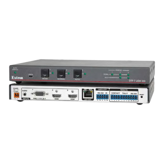
DTP receiver. This guide describes how to install, operate, and configure the switcher. NOTE: In this guide, the DTP T USW 333 is commonly referred to as a “switcher” or a “switching transmitter.” About the DTP T USW 333 Switcher The DTP T USW 333 is a 3 input VGA and HDMI switcher with a DTP transmitter output (see figure 1). -
Page 8: Stp Cable
The DTP T USW 333 is housed in a half rack width metal enclosure. It can be set on a tabletop or mounted in a rack, or under or through furniture. The included external desktop 12 VDC power supply accepts 100 to 240 VAC, 50‑60 Hz. A single power supply connected to either unit can power both units through the STP cable. -
Page 9: Installation And Operation
Installation and Operation This section describes the installation and the operation of the DTP T USW 333, including: Mounting the Unit • • Connections and Reset Button Operation • • Troubleshooting — If no Image Appears Mounting the Unit Mounting instructions can be found in Mounting the Switcher on page 18. - Page 10 • If you have removed the ground jumpers (see Disconnecting the Ground page 19) because of ground potential differences, the DTP T USW 333 cannot extend analog audio. The connected receiver outputs no analog audio. • The analog audio can be assigned to a specific input or set to be always...
-
Page 11: Connector And Cable Details
STP Cable Termination NOTE: Do not use Extron UTP23SF‑4 Enhanced Skew‑Free AV UTP cable or STP201 cable to link the switching transmitter and receiver. The DTP T USW 333 Tx/Rx does not work properly with these cables. DTP T USW 333 • Installation and Operation... - Page 12 Supported cables The DTP T USW 333 is compatible with shielded twisted pair (STP) and unshielded twisted pair (U/UTP) cable. However, Extron strongly recommends that you use STP cable to achieve best performance. Cable recommendations Extron recommends using the following practices to achieve full transmission distances up to 330 feet (100 meters) and reduce transmission errors.
- Page 13 The ridges on the side of the cord (see figure 5) identify the power cord negative lead. To verify the polarity before connection, plug in the power supply with no load and check the output with a voltmeter. DTP T USW 333 • Installation and Operation...
-
Page 14: Front Panel Configuration Port
NOTE: A front panel Configuration port connection and a rear panel Remote RS‑232 port connection can both be active at the same time. If commands are sent simultaneously to both, the command that reaches the processor first is handled first. DTP T USW 333 • Installation and Operation... -
Page 15: Operation
Auto(switch) button — The Auto button is used with the Mode button to select auto‑ Selecting the switch mode input switching mode (see on page 11). This button is a secondary function of the Input 3 button. DTP T USW 333 • Installation and Operation... -
Page 16: Front Panel Operations
NOTE: The switcher must be in normal (manual) mode. An input can also be selected using an RS‑232 or USB device or a contact closure device Remote Control, beginning on page 12). (see DTP T USW 333 • Installation and Operation... -
Page 17: Troubleshooting - If No Image Appears
Ensure an active input is selected on the switcher or that the switcher is in auto‑input switching mode. Ensure that the proper signal format is supplied. Check the cabling and make corrections as necessary. Call the Extron S3 Sales & Technical Support Hotline if necessary. DTP T USW 333 • Installation and Operation... -
Page 18: Remote Control
• Simple Instruction Set Control The DTP T USW 333 switcher can be remotely controlled via its rear panel Remote RS‑232 port, its front panel configuration (USB) port, and its rear panel Remote Contact port. Remote control devices can be: •... -
Page 19: Simple Instruction Set Control
Simple Instruction Set Control The DTP T USW 333 switching transmitter can be remotely controlled using SIS commands from a host device such as a computer or control system via its rear panel Remote RS‑232 port (see item on page 5) or front panel Configuration (USB) port (see item page 8). -
Page 20: Using The Command And Response Table
= Firmware version number to second decimal place (x.xx) = Verbose mode 0 = clear/none (default) 2 = tagged responses for queries 1 = verbose mode (default for RS‑232 or USB) 3 = verbose mode and tagged for queries DTP T USW 333 • Remote Control... - Page 21 = Input HDCP status = No source detected = Source detected with HDCP = Source detected without HDCP = Output HDCP status = No sink detected = Sink detected with HDCP = Sink detected without HDCP DTP T USW 333 • Remote Control...
- Page 22 = EDID See table 1, above. = User EDID location , or = Raw EDID data 128 or 256 bytes of hexadecimal data = Resolution and rate in plain text Example: • 1920x1200 @60Hz DTP T USW 333 • Remote Control...
- Page 23 = Firmware version number to second decimal place (x.xx) = Verbose mode 0 = clear/none (default) 2 = tagged responses for queries 1 = verbose mode (default for RS‑232 or USB) 3 = verbose mode and tagged for queries DTP T USW 333 • Remote Control...
-
Page 24: Reference Information
(see Disconnecting the Ground on the next page). The 1‑inch high, half rack width DTP T USW 333 switching transmitter can be placed on a table, mounted in a rack, or mounted under a desk or table. Tabletop Use Affix the included rubber feet to the bottom of the unit and place it in any convenient location. -
Page 25: Ul Rack-Mounting Guidelines
(as suggested by a missing or unstable picture), remove the ground connection between the units as follows: NOTE: Once you have removed the ground jumpers, the DTP T USW 333 cannot extend analog audio and one unit cannot remotely power the other. No analog audio is output and the paired receiver requires its own dedicated power supply. - Page 26 Obtain a second 12 V power supply (one supply is provided with the switching transmitter and normally powers both units), and locally power both units (see Power supply wiring on page 7). DTP T USW 333 • Reference Information...
- Page 27 Extron Electronics makes no further warranties either expressed or implied with respect to the product and its quality, performance, merchantability, or fitness for any particular use. In no event will Extron Electronics be liable for direct, indirect, or consequential damages resulting from any defect in this product even if Extron Electronics has been advised of such damage.
Need help?
Do you have a question about the DTP T USW 333 and is the answer not in the manual?
Questions and answers