
Related Manuals for Themis RES-XR4-1U


Summary of Contents for Themis RES-XR4-1U
- Page 1 User Manual User Manual Installation Installation Manual Manual Version 1.5 Pa r t N u m b e r : 119708- 024 1RU 19 ” Rac k- M ount Rugged Enter prise Ser ver Suppor ting X9DRW, X9DBU and X9SCi M other board s...
- Page 2 version version version version version version version version...
- Page 3 RES-XR4-1U Installation Manual* Version 1.5— June 2014 * Supports SuperMicro X9DRW, X9DBU, and X9SCi Motherboards. Themis Computer—Americas and Pacific Rim Themis Computer—Rest of World 47200 Bayside Parkway 5 Rue Irene Joliot-Curie Fremont, CA 94538 38320 Eybens, France Phone (510) 252-0870...
- Page 4 Themis Computer assumes no responsibility for inaccuracies. Themis Computer retains the right to make changes to this publication at any time without prior notice. Themis Computer does not assume any liability arising from the application or use of this publication or the product(s) described herein.
- Page 5 RES-XR4-1U Installation Manual Version Revision History Version 1.5 ..................June 2014 • Added German translation to the safety section of this manual • minor edits and changes throughout this manual Version 1.4 .................. January 2014 • Updated the Safety section of the manual •...
- Page 6 RES-XR4-1U Installation Manual Version 1.5 Version 1.3.................. October 2013 • Added Power Supply Monitoring section in Chapter 1. Version 1.2.................. October 2013 • Updated Specs and DC power supply information, and added version 2 CPU information. Version 1.1..................August 2013 • Added all available and planned motherboard configurations as of this date.
-
Page 7: Safety Instructions
(bay). Personal injury and equipment damage can occur. WARNING: All equipment connected to the product must conform to their standards WARNING: This Themis PRODUCT must be used in sheltered environments only, and at an altitude of less than 3048 meters (10,000 ft). - Page 8 In these cases, the device must be shut down and secured against unintentional operation. • Repairs/service may only be carried out by a Themis Computer qualified ser- vice technician. • Do not open the chassis, or perform services/repairs when the equipment is powered on, due to electrical shock hazard.
-
Page 9: Grounding Methods
RES-XR4-1U Installation Manual Safety Instructions not allow yourself to be exposed to this radiation. The laser system meets the code of Federal Regulations 21 CFR,1040 for the USA and Canadian Radiation Emitting Devices Act, REDR C 1370. Electrostatic Discharge (ESD) A sudden discharge of electrostatic electricity can destroy static-sensitive devices or micro-circuitry. - Page 10 RES-XR4-1U Installation Manual Version 1.5 6. Turn off power and input signals before inserting and removing connectors or test equipment. Power is not considered off until all power supplies have been disconnected. 7. Keep the work area free of non-conductive materials such as ordinary plastic as- sembly aids and Styrofoam.
- Page 11 RES-XR4-1U Installation Manual Safety Instructions European Union Waste Disposal This section is for waste disposal by users in private households in the European Union. For all others, please follow all local and government guidelines in accordance with waste disposal and the symbol seen below.
- Page 12 Personenschäden und zur Beschädigung des Geräts führen. Warnhinweis: Alle Geräte, die an das Produkt angeschlossen werden, müssen ihren Standards entsprechen. Warnhinweis: Dieses THEMIS-Produkt darf nur in geschützten Umgebungen und in einer Höhe von weniger als 3.048 Metern (10.000 ft) eingesetzt werden •...
- Page 13 In diesen Fällen muss das Gerät ausgeschaltet und gegen unbeabsichtigte Inbetriebnahme gesichert werden. • Reparaturen dürfen nur von Beauftragten der Firma Themis Computer durch- geführt werden. • Das Öffnen des Gerätes ist nur zulässig für den Ein- und Ausbau von Erweit- erungskarten (PCI), Speichermodulen, Festplatten, Lüftergehäusen, Netz-...
- Page 14 RES-XR4-1U Betriebshandbuch Version 1.5 Sie sich dieser Strahlung keinesfalls aus. Das Lasersystem erfüllt die Anforderungen des Code of Federal Regulations 21 CFR,1040 (für die USA) und des Canadian Radiation Emitting Devices Act, REDR C 1370 (für Kanada). Elektrostatische Entladung (ESD) Eine plötzliche elektrostatische Entladung kann empfindliche Geräte oder Mikros-...
- Page 15 RES-XR4-1U Betriebshandbuch Sicherheitshinweise 6. Verwenden Sie am Arbeitsplatz keine nichtleitenden Materialien, wie gewöhn- liche Kunststoffmontagehilfen oder Styropor. 7. Benutzen Sie leitende Werkzeuge (z.B. Messer, Schraubendreher und Staubsau- ger). 8. Legen Sie Laufwerke und Platinen immer mit der Bauteilseite nach unten auf die Schaumstoffunterlage.
- Page 16 RES-XR4-1U Betriebshandbuch Version 1.5 Themis Computer...
-
Page 17: Table Of Contents
1.7.3.1 I2C Notes .................. 1-21 1.7.3.2 Sample I2C Commands ............1-21 1.7.4 ACPI Features ..................1-22 1.7.5 Slow Blinking LED for Suspend-State Indicator ........1-22 1.7.6 Super I/O ....................1-22 1.7.7 Overview of the Renesas SH7757 ............1-22 Themis Computer... - Page 18 2.1.4.1 Removing the Lithium Battery ..........2-15 2.1.4.2 Installing a Lithium Battery ............2-16 2.1.5 Storage Drive ................... 2-17 2.1.5.1 Opening the RES-XR4-1U Front Doors ........2-17 2.1.5.2 Storage-Drive Removal ............2-18 2.1.5.3 Storage Drive Installation ............2-20 2.1.6 Cooling Fans .................... 2-20 2.1.6.1 Removing and Installing the 40-mm Fan Assembly ....
- Page 19 3.3.1.2 AddOn ROM Display Mode ............3-5 3.3.1.3 Bootup Num-Lock ..............3-5 3.3.1.4 Wait For 'F1' If Error ..............3-6 3.3.1.5 Interrupt 19 Capture ..............3-6 3.3.2 Power Configuration .................. 3-6 3.3.2.1 Watch Dog Function ..............3-6 xvii Themis Computer...
- Page 20 RES-XR4-1U Installation Manual Version 1.5 3.3.2.2 Power Button Function ............... 3-6 3.3.2.3 Restore on AC Power Loss ............3-6 3.3.3 CPU Configuration ..................3-6 3.3.3.1 Socket 1 CPU Information/Socket 2 CPU Information ....3-7 3.3.3.2 CPU Speed .................. 3-7 3.3.3.3 Clock Spread Spectrum .............. 3-7 3.3.3.4 Hyper-threading ................
- Page 21 TXT (LT-SX) Configuration ............3-26 ® 3.3.16.1 Intel TXT (LT-SX) Hardware Support ........3-26 ® 3.3.16.2 Intel TXT (LT-SX) Configuration Settings ......3-26 ® 3.3.16.3 Intel TXT (LT-SX) Dependencies ......... 3-27 ® 3.3.17 Intel ME Subsystem ................3-27 Themis Computer...
- Page 22 RES-XR4-1U Installation Manual Version 1.5 3.3.18 iSCSI Configuration ................3-27 3.3.18.1 iSCSI Initiator Name ..............3-27 3.3.19 NIC Configuration ................... 3-28 3.3.19.1 Link Speed ................3-28 3.3.19.2 Wake On LAN (WOL) ............. 3-28 3.3.19.3 Blink LEDs (Range 0~15 seconds) ........... 3-28 3.3.19.4 Port Configuration Information ..........
- Page 23 Appendix D. Optional RES Audio/USB/Serial Port Module ........D-1 D.1 RES Audio/USB/Serial Port Custom Module ............D-1 D.1.1 Attach I/O Cables ..................D-3 D.1.2 Connector Pinouts ..................D-4 D.1.2.1 USB Ports A and B ..............D-4 D.1.2.2 Serial Port COM1 ..............D-5 Themis Computer...
- Page 24 RES-XR4-1U Installation Manual Version 1.5 D.1.2.3 Stereo Audio Ports (Optional) ........... D-6 D.2 Ordering the RES Audio/USB/Serial Port Custom Module ......... D-7 Appendix E. Repackaging Instructions ................E-1 E.1 Repackaging for Shipment ..................E-1 E.2 Packaging Components ..................E-2 E.3 Instructions for Repackaging .................E-3 Index ..........................
- Page 25 X9DBU Motherboard Block Diagram............1-12 Figure 1-10 X9SCi Motherboard Block Diagram ............. 1-13 Figure 1-11 Top View of RES-XR4-1U with X9DBU Motherboard ........ 1-14 Figure 1-12 Top View of RES-XR4-1U with X9DRW Motherboard ....... 1-15 Figure 1-13 Top View of RES-XR4-1U with X9SCi-LN4F Motherboard....... 1-16 Figure 2-1 Remove the RES-XR4-1U Protective Access Cover ........
- Page 26 RES-XR4-1U Storage Drive Removal ............2-19 Figure 2-17 DC Power Supplies ..................2-22 Figure 2-18 Remove each Power Cord from the RES-XR4-1U rear chassis ....2-23 Figure 2-19 Remove the Power Cord Retention Bracket ..........2-24 Figure 2-20 The RES-XR4-1U Rear Grounding Screw and Kep Nut ......2-25 Figure 2-21 The RES-XR4-1U Power Supply Locking Mechanism ........
- Page 27 Figure A-4 VGA Connector Pinout................... A-4 Figure B-1 Screw Locations for Rack-Mount Slides ............B-1 Figure B-2 RES-XR4-1U Rack-Mount Slide Installation..........B-3 Figure C-1 Power On after Linux DVD is Inserted into Drive .......... C-2 Figure C-2 Skip Key ......................C-2 Figure C-3 Welcome Screen ....................
- Page 28 Figure E-1 Packaging Components..................E-2 Figure E-2 Order of Assembly................... E-4 List of Tables Table 1-1 Major Features of RES-XR4-1U ..............1-2 Table 1-2 RES-XR4-1U Motherboard Specifications ............ 1-3 Table 1-3 System LEDs ....................1-6 Table 1-4 Power Supply LED Behavior ................. 1-7 Table 1-5 Rear-Panel I/O Connectors ................
-
Page 29: Table
Unit Identifier Switch Status................A-5 Table D-1 Dual USB Connector Pinout Signal Descriptions (J10) ........ D-4 Table D-2 COM1 Serial Connector Pinout Signal Descriptions (J8 and J9) ....D-5 Table D-3 Stereo Audio Out Connector Pinout Signal Descriptions (J1) ...... D-6 xxvii Themis Computer... - Page 30 RES-XR4-1U Installation Manual Version 1.5 xxviii Themis Computer...
-
Page 31: Preface
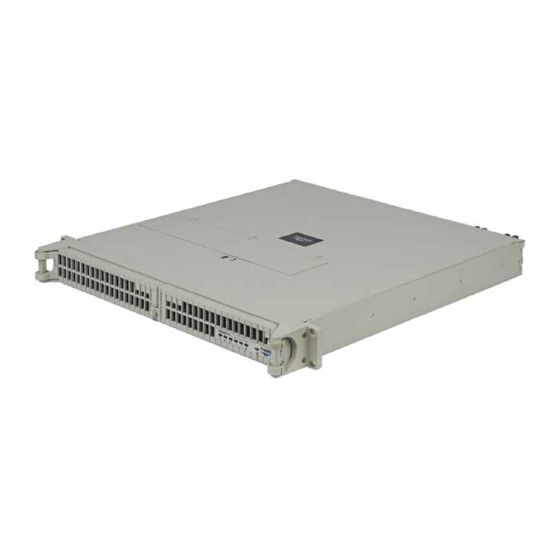
Preface This document, entitled RES-XR4-1U Installation Manual, provides instructions on how to install, configure, power up, and boot the Themis Rugged Enterprise Server RES-XR4-1U (see Figure 1 below). Figure 1. Rugged Enterprise Server RES-XR4-1U The RES-XR4-1U supports the following motherboards in a 20”-deep chassis: •... - Page 32 RES-XR4-1U Installation Manual Version 1.5 The 1RU-high (1.75”) RES-XR4-1U has been designed to fit into a standard 19” rack and is provided with rack-mount brackets with handles. Optional rack-mount slides are also available. The RES-XR4-1U is rugged enough to withstand extreme shock (up to 30 g), temperature, and EMI as that associated with such demanding markets as the military, aerospace, and telecommunications industries.
- Page 33 To reduce the risk, follow the in- structions accompanying this symbol. Sidebar: A “sidebar” adds detail to the section within which it is placed, but is not absolutely vital to the description or procedure of the section. xxxi Themis Computer...
- Page 34 RES-XR4-1U Installation Manual Version 1.5 xxxii Themis Computer...
-
Page 35: Overview And Specifications
General Section Chapter Overview and Specifications Overview The RES-XR4-1U (see Figure 1-1 below) is a rack-mounted high-performance sys- tem designed specifically for above-average shock and vibration environments. The ® RES-XR4-1U supports single or dual Intel Xeon™ processors, as indicated in Table 1-2 on page 1-3, and includes multiple GBs of 1866/1600/1333/1066/800- MHz DDR3 ECC Registered memory modules. -
Page 36: Table 1-1 Major Features Of Res-Xr4-1U
RES-XR4-1U Installation Manual Version 1.5 The RES-XR4-1U is designed within a 1RU-high (1.75”) form-factor, a rack depth either 20” (50.8 cm) or 17” (43.2 cm) deep, and 17” (43.2 cm) wide (which, with mounting brackets, fits a 19”-wide rack. Table 1-1. Major Features of RES-XR4-1U... -
Page 37: External Features
Right Slot d—One PCI-e x4 in x8 slot e—PCI-e 3.0, Riser card support with E3-1200 V2 series CPU 1.1.1 External Features The RES-XR4-1U front panel houses three removable storage drives. System Power CD-RW/DVD-ROM Front View (Doors Removed) ON/OFF Switch Combo Slimline Drive 1.75”... -
Page 38: Figure 1-3 Res-Xr4-1U Motherboard I/O Options
X9SCi I/O Panel Power Supply (as viewed from AC Power Socket Latch Lock rear of system) (3-prong NEMA 15) Rear I/O Panel (see Figure 1-6, page 1-11) Lower Right PCI Slot, Right Riser Figure 1-3. RES-XR4-1U Motherboard I/O Options Themis Computer... -
Page 39: Front Panel And System Leds
1—Overview and Specifications Front Panel and System LEDs All RES-XR4-1U system LEDs are located on the front panel. LEDs are described in Table 1-3. Power supply LED behavior is described by Table 1-4 on page 1-7. Front Panel (Doors Removed) -
Page 40: Table 1-3 System Leds
RES-XR4-1U Installation Manual Version 1.5 Table 1-3. System LEDs Symbol Description Power Indicates that the system is turned on. Storage Drive Indicates storage-drive activity. ENET1 NIC1 (Gb Ethernet) Indicates network activity on LAN 1. < > ENET2 NIC2 (Gb Ethernet) ... -
Page 41: Table 1-4 Power Supply Led Behavior
LED behavior indicates that DC power is not being used, and the system is off. It does not indicate a loss of AC power to the power supply module. Themis Computer... -
Page 42: Rear Panel I/O
RES-XR4-1U Installation Manual Version 1.5 Rear Panel I/O The following illustrations depict the rear I/O panels for each motherboard option available. Table 1-5 on page 1-10 describes the I/O connectors. Right Power Left Power Supply(PS2) Supply(PS1) Left Side Slot PCI Expansion Card... -
Page 43: Figure 1-6 Rear Panel I/O For X9Dbu Motherboard
LAN 3 LAN 4 UID Switch Keyboard Mouse Rear I/ O Panel VGA (Blue) LAN 1 LAN 2 USB 1 (top) COM Por t 1 USB 0 (bottom) ( Turquoise) Gigabit Ethernet Figure 1-7. Rear Panel I/O for X9SCi-LN4F Motherboard Themis Computer... -
Page 44: Table 1-5 Rear-Panel I/O Connectors
RES-XR4-1U Installation Manual Version 1.5 Table 1-5. Rear-Panel I/O Connectors Connector Description PS/2 Mouse 6-pin mini-DIN connector to attach a PS/2 mouse device (X9DBU / X9SCi-LN4F). PS/2 Keyboard 6-pin mini-DIN connector to attach a PS/2 keyboard device (X9DBU / X9SCi-LN4F). -
Page 45: Block Diagrams
PET8 USB [10,11] LPC Renesas HW Monitor Super I/O CONN RTL8211E W83527 NCT7904D IPMI LAN RJ45 Figure 1-8. X9DRW Motherboard Block Diagram a—This represents a general block diagram of the X9DRW board and does not necessarily depict specific system configurations 1-11 Themis Computer... -
Page 46: Figure 1-9 X9Dbu Motherboard Block Diagram
RES-XR4-1U Installation Manual Version 1.5 #F-2 #F-1 #E-2 #C-2 #E-1 #C-1 #D-2 #B-2 #D-1 #B-1 CPU1 CPU2 #A-2 QP I #A-1 DDR3 DDR3 #3A/B #3C/D #1B #1A DM I #1A/B #3C/D Uplink DMI PCI-E X8 G3 PCI-E X8 G3 PCI-E... -
Page 47: Figure 1-10 X9Sci Motherboard Block Diagram
SPI 32Mb NCT6776F PS/2 RTL 8201 LPC I/O PORT COM1,2 HEAL TH INFO Figure 1-10. X9SCi Motherboard Block Diagram a—This represents a general block diagram of the X9SCi board and does not nec- essarily depict specific system configurations 1-13 Themis Computer... -
Page 48: Internal Views
CPU 1 Modules (CPU 2) 6 DIMM Memory Modules (CPU 1) Lithium Battery 40-mm Fan (Five Total) Front CD/DVD Storage Drive Combo-Drive (Total of 3) Housing Figure 1-11. Top View of RES-XR4-1U with X9DBU Motherboard—Air Diverter Removed 1-14 Themis Computer... -
Page 49: Figure 1-12 Top View Of Res-Xr4-1U With X9Drw Motherboard
4 DIMM Memory 4 DIMM Modules (CPU 1) Memory Modules (CPU 1) Lithium Battery 40-mm Fan (Five Total) Front CD/DVD Storage Drive Combo-Drive (Total of 3) Housing Figure 1-12. Top View of RES-XR4-1U with X9DRW Motherboard—Air Diverter Re- moved 1-15 Themis Computer... -
Page 50: Figure 1-13 Top View Of Res-Xr4-1U With X9Sci-Ln4F Motherboard
Riser Card Slot PCI-Express Card (Upper Right Slot) 4 DIMM Memory Modules Lithium Battery 40-mm Fan (Five Total) Front CD/DVD Storage Drive Combo-Drive (Total of 3) Housing Figure 1-13. Top View of RES-XR4-1U with X9SCi-LN4F Motherboard—Air Diverter Removed 1-16 Themis Computer... -
Page 51: Processor And Chipset Overview
PCH C602/C606 Chipset (X9DRW), or the Intel E5-2400 (X9DBU) and the PCH C602/C606 Chipset, the RES-XR4-1U provides the performance required for dual processor-based high-end systems, including optimal configuration options for communications, high-end CAD systems, or database applications. RES-XR4- ®... -
Page 52: C204 Chipset
RES-XR4-1U Installation Manual Version 1.5 • Up to 20MB of cache per CPU ® • Enhanced Intel SpeedStep Technology ® • Two full-width Intel QuickPath interconnect link(s), up to 8.0 GT/s of data trans- fer rate in each direction • Virtualization Technology, Integrated Management Engine supported •... -
Page 53: Main Features Of The E3-1200 Series Processor And C204 Chipset
CPU cores, +1.8V, +3.3V, +5V, +12V, +3.3V Standby, +5V Standby, VBAT, Memory, Chipset Voltages. Once a voltage becomes unstable, a warning is given or an error message is sent to the screen. Users can adjust the voltage thresholds to define the sensitivity of the voltage monitor. 1-19 Themis Computer... -
Page 54: Fan Status Monitor
1.7.3 Power Supply Monitoring The power supplies in the Themis RES servers support a feature allowing their status to be queried directly through software. The power supplies are connected to an I bus used for system monitoring. This bus can be reached through the Baseboard Management Controller (BMC), (described in subsequent paragraphs), on the moth- erboard. -
Page 55: Sample I2C Commands
0c = 00001100. Bits 2 and 3 are 1, so both power supplies are operating. Where: <your-ip-address> is the IP address of the BMC. -UADMIN is the user name of the administrative user of the BMC. -PADMIN is the password of the administrative user of the BMC. 1-21 Themis Computer... -
Page 56: Acpi Features
RES-XR4-1U Installation Manual Version 1.5 1.7.4 ACPI Features Advanced Configuration and Power Interface (ACPI) defines a flexible and abstract hardware interface that provides a standard method of integrating power manage- ment features throughout the system. This includes the hardware, the operating sys- tem, and the application software. -
Page 57: Bmc Subsystem Features
(BMC). The Nuvoton WPCM450R Controller, a Baseboard Management Controller (BMC), supports 2D/VGA-compatible Graphic Cores with PCI interface, creating multi- media virtualization via Keyboard/Video/Mouse Redirection (KVMR). The WPCM450R Controller is ideal for remote system management. 1-23 Themis Computer... -
Page 58: Wpcm450R Ddr2 Memory Interface
RES-XR4-1U Installation Manual Version 1.5 The WPCM450R Controller interfaces with the host system via PCI connections to communicate with the graphics cores. It supports USB 2.0 and 1.1 for remote key- board/mouse/virtual media emulation. It also provides LPC interface support to con- trol Super IO functions. - Page 59 1—Overview and Specifications Special Features Interface) • RMCP+ protocol supported Note: For more information regarding IPMI configuration, refer to the IPMI Us- er’s guide on SuperMicro’s website at, http://www.supermicro.com/support/man- uals/ 1-25 Themis Computer...
-
Page 60: Specifications
RES-XR4-1U Installation Manual Version 1.5 Specifications 1.8.1 General Table 1-6. RES-XR4-1U General Specifications Parameter Description Dimensions 1.75” (44.45mm)(1RU) high 17.06” (433.3 mm) wide (19” rack-mountable) 20” (508 mm) deep Weight 19.5 lb (8.9 kg) Left and right rack-mount tabs attached to chassis 19”... -
Page 61: Electrical
= Not Applicable. 1.8.2.1 System Power The RES-XR4-1U operates with two N+1 redundant power supplies of 750-watts capacity each that auto-range single-phase AC input from 100 to 240 Vac (47 to 63 Hertz) sources. Filtered and fused (internal) AC is supplied to each power supply from a rear-mounted power connection. -
Page 62: Output Voltage
3-axis shock load of 25 g at 25-ms duration, half sine pulse. 1.8.3.2 Electrostatic Discharge The RES-XR4-1U is designed to tolerate electrostatic pulses up to 15 kilovolts (KV) with no impact on system operation. 1.8.3.3 Noise The RES-XR4-1U conforms to the 54-db noise specification Note: All RES systems are shipped with BIOS fan speed set to the quietest mode. -
Page 63: Packaging And Shipping
D. Any applicable paperwork When you unpack the RES-XR4-1U, please verify that all of these items are included. If any of these items are missing or not as pictured, please call Themis Technical Support at 510-252-0870, or send an email to support@themis.com. -
Page 64: Rack-Mount Slides (Optional)
1.10 Rack-Mount Slides (Optional) Rack-Mount Slides can be mounted on each side of the RES-XR4-1U for the pur- pose of sliding the unit in and out of a rack. Mounting slides are optional and can be ordered at the time of purchase. -
Page 65: Res System
Depth Description (Approximate) Sockets 19.5 lbs (8.9 kg) 20” Includes: All CPU sockets filled 6 DIMMs RES-XR4-1U 2 storage drives 2 PCI cards 17 lbs (7.7 kg) 17” 1 CD-RW/DVD-ROM drive 2 power supplies 25 lbs (11.4 kg) - Page 66 2 power supplies a—These are “typical” weights for a RES system. Please contact Themis for the exact weight of your configured system. b—Number represents total possible CPU sockets per system. Total of two CPU sockets per compute module. 1-32...
- Page 67 1—Overview and Specifications RES System 1-33 Themis Computer...
- Page 68 RES-XR4-1U Installation Manual Version 1.5 1-34 Themis Computer...
-
Page 69: Installation And Operation
• How to install a memory module, storage drive, PCI card, 40-mm-fan, power supply, and lithium battery • Rack-mount brackets • How to turn the RES-XR4-1U on and off Installation Procedures Caution: Use industry-standard ESD grounding techniques when handling all components. -
Page 70: Figure 2-1 Remove The Res-Xr4-1U Protective Access Cover
1. Loosen the two captive Phillips screws holding the protective top access cover to the rear of the RES-XR4-1U chassis (see A, Figure 2-1). 2. Both the front and sides of the cover have flat hooks or tabs underneath that fit under slots on the chassis top edges (see B, Figure 2-1). -
Page 71: Memory Modules
2.1.2 Memory Modules The RES-XR4-1U supports memory according to Table 2-1. Note the total memory capacity varies according to the motherboard installed in the RES-XR4-1U. Memory location is as depicted in Figures 2-2 and 2-3. Table 2-1. -
Page 72: Table 2-2 X9Dbu-3/If Mb Memory Population
RES-XR4-1U Installation Manual Version 1.5 Table 2-2. X9DBU-3/iF MB Memory Population CPU# X9DBU Motherboard CPU 1 P1-DIMMA1 P1-DIMMA2 P1-DIMMB1 P1-DIMMB2 P1-DIMMC1 P1-DIMMC2 CPU 2 P2-DIMMD1 P2-DIMMD2 P2-DIMME1 P2-DIMME2 P2-DIMMF1 P2-DIMMF2 Table 2-3. X9DRW-3/iF MB Memory Population CPU # X9DRW Motherboard... -
Page 73: Table 2-5 X9Dbu-3/If Optimal Memory Population
(For best performance, populate the memory in pairs) CPU 1 1 CPU & 2 DIMMs P1-DIMM 1(A or B), P1-DIMM 2(A or B) CPU 1 1 CPU & 4 DIMMs P1-DIMM 1A, P1-DIMM 1B, P1-DIMM 2A, P1-DIMM 2B Themis Computer... -
Page 74: Memory Module Location
RES-XR4-1U Installation Manual Version 1.5 2.1.2.1 Memory Module Location P2 DIMM D1 P2 DIMM D2 P2 DIMM E1 P2 DIMM E2 P2 DIMM F1 P2 DIMM F2 P1 DIMM C2 P1 DIMM C1 P1 DIMM B2 P1 DIMM B1 P1 DIMM A2 P1 DIMM A1 Figure 2-2. -
Page 75: Figure 2-3 Memory Module Slot Locations (X9Drw-3/If Motherboard)
P2 DIMM G2 P2 DIMM G1 P2 DIMM D2 P2 DIMM D1 P1 DIMM C2 P1 DIMM C1 P1 DIMM B2 P1 DIMM B1 P1 DIMM A2 P1 DIMM A1 Figure 2-3. Memory Module Slot Locations (X9DRW-3/iF Motherboard) Themis Computer... -
Page 76: Figure 2-4 Memory Module Slot Locations (X9Sci-Ln4F Motherboard)
RES-XR4-1U Installation Manual Version 1.5 Channel 1 Slot 1A Channel 1 Slot 1B Channel 2 Slot 2A Channel 2 Slot 2B Figure 2-4. Memory Module Slot Locations (X9SCi-LN4F Motherboard) Themis Computer... -
Page 77: Installation
2—Installation and Operation Installation Procedures 2.1.2.2 Installation The following procedure explains how to install the DDR3 FBD Memory Modules. 1. Loosen and remove the seven screws securing the air-flow deflector (see Fig- ure 2-5). Figure 2-5. Remove RES-XR4-1U Air-Flow Deflector Themis Computer... -
Page 78: Figure 2-6 Memory Module Removal
RES-XR4-1U Installation Manual Version 1.5 2. After the air-flow deflector is removed the memory modules will be exposed (see Figure 2-2 on page 2-6 and Figure 2-3 on page 2-7). The following procedure explains how to install the Memory Modules... -
Page 79: Pci Cards
2.1.3 PCI Cards Since the RES-XR4-1U is only 1RU (1.75”) high, PCI cards must be installed hori- zontally through the use of PCI Riser Cards (see Figure 2-7 on page 2-11). The upper-right PCI slot supports cards up to 12.28-inches long; the lower-right and left PCI slot supports shorter cards. -
Page 80: Installing Cards
RES-XR4-1U Installation Manual Version 1.5 Retainer Bracket Retainer Bracket Screws Universal I/O (UIO) Right Riser Card PCI-Express 2.0 x16 Note: P/N of Riser Card shown = RSC-R1UU-UE16 Figure 2-8. PCI Riser Cards attached to Retainer Bracket Retainer Bracket Figure 2-9. - Page 81 Installation Procedures 2. Remove the blank I/O faceplate corresponding to the slot. Note: Call Themis Technical Support if there is a question on how to secure the PCI I/O faceplate to the rear I/O panel. 3. Carefully install each PCI card (lower-right card first) into the appropriate slot until all expansion cards have been installed.
-
Page 82: Figure 2-11 Installation Of The Pci Card Retainer Bracket
4. Attach any internal I/O cables to the installed PCI cards, and carefully fold and tuck any exposed ribbon cables into the cabinet. 5. If you have no further installations to perform, close the RES-XR4-1U chassis by refastening the top cover removed in Step 1 on page 2-2. -
Page 83: Lithium Battery
2. If you cannot access the lithium battery directly, you must move and/or detach the multiple wire cable routed over the battery. 3. Locate the lithium battery socket and squeeze the latch (see A, Figure 2-13 on page 2-16) together until the battery lifts out of its socket. 2-15 Themis Computer... -
Page 84: Installing A Lithium Battery
RES-XR4-1U Installation Manual Version 1.5 4. Remove the old battery and replace with a new battery (see Figure 2-13). Battery Latch To release, squeeze the battery latch together… … and remove the battery from socket Figure 2-13. Lithium Battery and Socket Note: Always dispose of used batteries in accordance with local guidelines and regulations. -
Page 85: Storage Drive
Note: For SATA II drives, the left-hand removable storage drive (SATA II ID0) is designated as the boot drive. The front bezel (door) of the RES-XR4-1U must be unlocked and opened to access the storage drives. 2.1.5.1 Opening the RES-XR4-1U Front Doors To access the removable storage drives, you must first open the front doors (see Fig- ure 2-14, page 2-17). -
Page 86: Storage-Drive Removal
After opening the front doors, perform the following steps to remove and install a storage drive: Note: Since RES-XR4-1U storage drives are “hot-swappable”, it is not necessary to turn off system power in order to remove and replace a drive (except the oper- ating system drive). -
Page 87: Figure 2-16 Res-Xr4-1U Storage Drive Removal
Storage Drive Screw (1 of 4) Place the four screws in a plastic envelope for safe keeping. Drive Holder Remove drive from drive holder. Figure 2-16. RES-XR4-1U Storage Drive Removal 2-19 Themis Computer... -
Page 88: Storage Drive Installation
2.1.6 Cooling Fans The RES-XR4-1U contains six high-speed 40-mm cooling fans. Each fan is an inte- gral part of the entire fan assembly, therefore if any fan needs to be replaced, the entire assembly must be replaced. The system must be powered down to replace the fan assembly. - Page 89 7. Insert and tighten the mounting screws in the mounting holes. 8. Connect each fan wiring header. 9. Replace the protective top cover as indicated in Section 2.1.1, “Remove Pro- tective Top Cover,” on page 2-1. 2-21 Themis Computer...
-
Page 90: Power Supply
RES-XR4-1U Installation Manual Version 1.5 Power Supply Power supplies may be ordered in pairs to provide N+1 load-sharing redundancy. Systems ordered with only one power supply module are supplied with a dummy/blank module installed in the other power supply bay. In such configuration there is no redundancy in the power supply subsystem. -
Page 91: Removing A Power Supply
(see B, Figure 2-19 on page 2-24). Tie Wrap Power Cord Retention Bracket Cut and remove the cable tie wrap securing each AC power cord to the Power Cord Retention Bracket. Figure 2-18. Remove each Power Cord from the RES-XR4-1U rear chassis 2-23 Themis Computer... -
Page 92: Figure 2-19 Remove The Power Cord Retention Bracket
RES-XR4-1U Installation Manual Version 1.5 3. Place the Bracket in a safe place for future use. Remove Screw Remove Screw Place Bracket in a safe place for future use. Figure 2-19. Remove the Power Cord Retention Bracket 2-24 Themis Computer... -
Page 93: Chassis Grounding Screw
10-32 Hex Kep Nut (both sides shown) Note: Two Kep Nuts are required to secure a RES-XR4 ground wire to a chassis Single Kep Nut (top and bottom views) Figure 2-20. The RES-XR4-1U Rear Grounding Screw and Kep Nut 2-25 Themis Computer... -
Page 94: Installing A Power Supply
Locking Lever locking bracket Handle Figure 2-21. The RES-XR4-1U Power Supply Locking Mechanism 2.2.3 Installing a Power Supply Perform the following steps to install a power supply: 1. Insert the replacement power supply into an empty slot with the power LED at the top (see Figure 2-21). -
Page 95: Installing A Power Cord Retention Bracket
Power Cord Retention Bracket. Perform the following steps to install a Power Cord Retention Bracket: 1. Secure the Retention Bracket to the rear of the RES-XR4-1U chassis with its two captive screws (see Figure 2-22). Captive... -
Page 96: Figure 2-23 The Res-Xr4-1U Power Cord Retention Bracket
Tie Wrap Plug in one of the AC power cords … then secure it with a tie wrap. Repeat Steps A and B to connect a second AC power cord. Figure 2-23. The RES-XR4-1U Power Cord Retention Bracket 2-28 Themis Computer... -
Page 97: Installing A Usb Cable Retention Bracket
Power Supply 2.2.5 Installing a USB Cable Retention Bracket Note: Your RES-XR4-1U is shipped without a USB Cable Retention Bracket in- stalled (see Figure 2-24). Follow the steps of this section to properly install a USB Cable Retention Bracket. 1. The USB Cable Retention Bracket is attached to the chassis with three Phillips head screws, which are shipped with your order (see A, Figure 2-24). -
Page 98: Rack Mounts
To learn how to install rack-mount slides, refer to Appendix B, “Rack-Mount Slide Installation”. Caution: Any screws used to mount a slide to a RES-XR4-1U chassis must not ex- ceed a length of 6mm to prevent excessive penetration of the chassis. -
Page 99: Operation
Before powering on the RES-XR4-1U, plug in the AC power cords as follows: 1. On the rear of the RES-XR4-1U, plug an AC power cord (shipped with unit) into the AC power socket on each power supply (see Figure 2-26). -
Page 100: Getting Started
1. To turn the RES-XR4-1U power off, press and hold the system power on/off button (see Figure 2-27, page 2-31) for at least four (4) seconds. This will shut down the system and turn off the POWER LED as well as the LED on the power supply unit(s). -
Page 101: Bios Setup Utility
To view the AMI BIOS Setup Utility screens, press the <Delete> key while the sys- tem is booting up. Note: In most cases, the <Delete> key is employed to view the AMI BIOS setup screen. There are a couple of cases when other keys are used, including <F1>, <F2>, etc. Themis Computer... -
Page 102: How To Change The Configuration Data
When an option is selected in the left frame, it is highlighted in white. Often a text message will accompany it. Note: The AMI BIOS has default text messages built in. Themis has the option to include, omit, or alter any of these text messages. -
Page 103: Main Bios Setup
Employ this option to alter the system time and date. Highlight System Time or Sys- tem Date using the arrow keys. Key in new values through the keyboard and press <Enter>. Press the <Tab> key to move between fields. The date has be entered in Themis Computer... -
Page 104: Ami Bios
RES-XR4-1U Installation Manual Version 1.5 Day MM/DD/YY format. The time is entered in HH:MM:SS format. Note: The time is in the 24-hour format. For example, 5:30 P.M. appears as 17:30:00. 3.2.1.2 AMI BIOS • Motherboard Model Name: Motherboard manufacturer’s model number •... -
Page 105: Boot Features
This sets the display mode for Option ROM. Select Keep Current to use the current AddOn ROM Display setting. Select Force BIOS to use the Option ROM display mode set by the system BIOS. The options are Force BIOS (default) and Keep Cur- rent. 3.3.1.3 Bootup Num-Lock Themis Computer... -
Page 106: Wait For 'F1' If Error
RES-XR4-1U Installation Manual Version 1.5 This feature selects the Power-on state for Numlock key. The options are Off and On (default). 3.3.1.4 Wait For 'F1' If Error This forces the system to wait until the 'F1' key is pressed if an error occurs. The options are Disabled and Enabled (default) 3.3.1.5 Interrupt 19 Capture... -
Page 107: Socket 1 Cpu Information/Socket 2 Cpu Information
The options are Enabled and Disabled. 3.3.3.5 Active Processor Cores Set to Enabled to employ a processor's Second Core and beyond. (Please refer to Intel's web site for more information.) The options are All (default), 1 and 2. Themis Computer... -
Page 108: Limit Cpuid Maximum
RES-XR4-1U Installation Manual Version 1.5 3.3.3.6 Limit CPUID Maximum This feature allows the user to set the maximum CPU ID value. Enable this function to boot the legacy operating systems that cannot support processors with extended- CPUID functions. The options are Enabled and Disabled (for the Windows OS). -
Page 109: Intel Virtualization Technology
Speedstep support used on older platforms. Please refer to Intel’s web site for detailed information. ® Intel TurboMode Technology (Available when Power Technol- ogy is set to Custom) Select Enabled to use the Turbo Mode to boost system performance. The options are Themis Computer... - Page 110 RES-XR4-1U Installation Manual Version 1.5 Enabled and Disabled. C1E Support (Available when Power Technology is set to Cus- tom) Select Enabled to enable Enhanced C1 Power State to maximize energy efficiency. The options are Disabled and Enabled. CPU C3 Report (Available when Power Technology is set to...
-
Page 111: Chipset Configuration
The options are Disabled and Enabled. ® Intel I/OAT The Intel I/OAT (I/O Acceleration Technology) significantly reduces CPU overhead by leveraging CPU architectural improvements, freeing resources for other tasks. The options are Disabled and Enabled (default). DCA Support 3-11 Themis Computer... -
Page 112: Iio 2 Pcie Port
RES-XR4-1U Installation Manual Version 1.5 Select Enabled to use Intel's DCA (Direct Cache Access) Technology to improve data transfer efficiency. The options are Disabled and Enabled. IIO 1 PCIe Port Bifurcation Control/IIO2 PCIe Port Bifurcation control This submenu configures the following IO PCIe Port Bifurcation Control settings for IIO 1 PCIe ports or IIO 2 PCIe ports to determine how the available PCI-Express lanes are distributed between the PCI-Express Root Ports. -
Page 113: Dimm Configuration
3.3.5.4 DIMM Information The status of the memory modules specified below will be displayed as detected by the BIOS. CPU Socket 1 DIMM Information P1-DIMMA1/P1-DIMMB1/P1-DIMMC1/P1-DIMMD1/P1-DIMMA2/P1- DIMMB2/ P1-DIMMC2/P1-DIMMD2 CPU Socket 2 DIMM Information P2-DIMME1/P2-DIMMF1/P2-DIMMG1/P2-DIMMH1/P2-DIMME2/P2- DIMMF2/P2-DIMMG2/P2-DIMMH2 Memory Mode 3-13 Themis Computer... -
Page 114: Channel Interleaving
RES-XR4-1U Installation Manual Version 1.5 When Independent is selected, all DIMMs are available to the operating system. When Mirroring is selected, the motherboard maintains two identical copies of all data in memory for data backup. When Lockstep is selected, the motherboard uses two areas of memory to run the same set of operations in parallel. -
Page 115: Southbridge Configuration
(If set to Enabled, EHCI Controller 1 and Controller 2 will appear.) EHCI Controller 1/EHCI Controller 2 (Available when All USB Devices are set to Enabled) Select Enabled to enable EHCI (Enhanced Host Controller Interface) Controller 1 or Controller 2. The options are Disabled and Enabled. 3-15 Themis Computer... -
Page 116: Sata Configuration
RES-XR4-1U Installation Manual Version 1.5 Legacy USB Support (Available when USB Functions is not Disabled) Select Enabled to support legacy USB devices. Select Auto to disable legacy support if USB devices are not present. Select Disable to have USB devices available for EFI (Extensive Firmware Interface) applications only. -
Page 117: Ahci Mode
Select Enabled to enable hot-plug support for the particular port. The options are Enabled and Disabled. 3.3.7 SCU (Storage Control Unit) Configuration 3.3.7.1 Storage Controller Unit Select Enabled to enable PCH SCU storage devices. The options are Disabled and Enabled. 3-17 Themis Computer... -
Page 118: Onchip Scu Option Rom
RES-XR4-1U Installation Manual Version 1.5 3.3.7.2 OnChip SCU Option ROM Select Enabled to support the onboard SCU Option ROM to boot up the system via a storage device. The options are Disabled and Enabled. 3.3.7.3 SCU Port 0-SCU Port 7 The BIOS will automatically detect the onboard SCU devices and display the status of each SCU device as detected. -
Page 119: Maximum Payload
Select iSCSI to use the iSCSI Option ROM to boot the computer using a network device. Select PXE (Preboot Execution Environment) to use an PXE Option ROM to boot the computer using a network device. The options are iSCSI and PXE. 3-19 Themis Computer... -
Page 120: Load Onboard Lan1 Option Rom/Load Onboard Lan2 Option Rom
RES-XR4-1U Installation Manual Version 1.5 3.3.8.11 Load Onboard LAN1 Option ROM/Load Onboard LAN2 Option Select Enabled to enable the onboard LAN1 Option ROM/LAN2 Option ROM. This is to boot the computer using a network device. The default setting for LAN1 Option ROM is Enabled, and the default setting for LAN2 Option ROM is Disabled. -
Page 121: Device Mode
COM Port selected by the user. Console Redirection Select Enabled to use a COM Port selected by the user for Console Redirection. The options are Enabled and Disabled. The default setting for COM1 is Disabled, and 3-21 Themis Computer... -
Page 122: Console Redirection Settings
RES-XR4-1U Installation Manual Version 1.5 for COM2 is Enabled. 3.3.12.1 Console Redirection Settings This feature allows the user to specify how the host computer will exchange data with the client computer, which is the remote computer used by the user. -
Page 123: Serial Port For Out-Of-Band Management/Windows Emergency Management Services (Ems)
The submenu allows the user to configure Console Redirection settings to support Out-of-Band Serial Port management. Select Enabled to use a COM Port selected by the user for Console Redirection. The options are Enabled and Disabled. 3.3.13.1 Console Redirection Settings (for EMS) 3-23 Themis Computer... -
Page 124: Acpi Settings
RES-XR4-1U Installation Manual Version 1.5 The feature allows the user to configure console redirection settings for a local machine to communicate with a remote server. Out-of-Band Management Port This feature selects a serial port used by the Microsoft Windows Emergency Man- agement Services (EMS) to communicate with a remote server. -
Page 125: Tpm State
Select Enabled to enable TPM security settings to improve data integrity and net- work security. The options are Disabled and Enabled. Pending Operation Use this item to schedule an operation for the security device. The options are None, 3-25 Themis Computer... -
Page 126: Current Status Information
RES-XR4-1U Installation Manual Version 1.5 Enable Take Ownership, Disable Take Ownership, and TPM Clear. Note: During restart, the computer will reboot in order to execute the pending Note: operation and change the state of the security device. 3.3.15.2 Current Status Information This item displays the information regarding the current TPM status. -
Page 127: Intel Txt (Lt-Sx) Dependencies
Discard the changes and exit from the page. • Change Attempt Order • Commit Changes and Exit Save the changes and exit from the page. • Discard Changes and Exit Discard the changes and exit from the page. 3-27 Themis Computer... -
Page 128: Nic Configuration
RES-XR4-1U Installation Manual Version 1.5 3.3.19 NIC Configuration 3.3.19.1 Link Speed This item allows the user to set the link speed for your network connections. The Options are AutoNeg (Auto Negotiation), 10 Mbps Half, 10 Mbps Full, 100 Mbps Half, and 10 Mbps Full. -
Page 129: Event Logs
Select Enabled to enable SMBIOS (System Management BIOS) Event Logging dur- ing system boot. The options are Enabled and Disabled. Runtime Error Logging Support Select Enabled to support Runtime Error Logging. The options are Enabled and Disabled. 3-29 Themis Computer... -
Page 130: Erasing Settings
RES-XR4-1U Installation Manual Version 1.5 Memory Correctable Error Threshold This feature allows the user to enter the threshold value for correctable memory errors. The default setting is 10. PCI Error Logging Support Select Enabled to support error event logging for PCI slots. The options are Enabled and Disabled. -
Page 131: View Smbios Event Log
3.4.2.5 View System Event Log This item allows the user to view the event in the system event log. Select this item and press <Enter> to view the status of an event in the log as shown below: Date/Time/Sensor/Type 3-31 Themis Computer... -
Page 132: Ipmi
RES-XR4-1U Installation Manual Version 1.5 IPMI Use this feature to configure Intelligent Platform Management Interface (IPMI) set- tings. Figure 3-4. IPMI Settings Screen IPMI Firmware Revision This item indicates the IPMI firmware revision used in your system. IPMI Status This item indicates the status of the IPMI firmware installed in your system. -
Page 133: Erasing Settings
This feature allows the BIOS to implement any IP/MAC address changes at the next system boot. If the option is set to Yes, any changes made to the settings below will take effect when the system is rebooted. The options are No and Yes. 3-33 Themis Computer... -
Page 134: Subnet Mask
RES-XR4-1U Installation Manual Version 1.5 Configuration Address Source This feature allows the user to select the source of the IP address for this computer. If Static is selected, you will need to know the IP address of this computer and enter it to the system manually in the field. -
Page 135: Boot Configuration
This item allows the user to select the first boot drive. Select a LAN device to boot the system from the network connection. Select UEFI to boot the system from the UEFI: Built-in EFI Shell. The options are LAN Device, UEFI: Built-in EFI Shell, and Disabled. 3-35 Themis Computer... -
Page 136: Usb Device Bbs Priorities
RES-XR4-1U Installation Manual Version 1.5 3.6.3 USB Device BBS Priorities 3.6.3.1 Hard Disk Drives Boot Option #1~ Boot Option #3 This item displays the first boot device. 3.6.3.2 Network Drives Boot Option #1 This item displays the first boot device. -
Page 137: Security Settings
Use this feature to set a User Password which is required to log into the system and to enter the BIOS setup utility. The length of the password should be from 3 charac- ters to 20 characters long. 3-37 Themis Computer... -
Page 138: Save And Exit
RES-XR4-1U Installation Manual Version 1.5 Save and Exit This submenu allows the user to configure the Save and Exit settings for the system. Figure 3-7. Exit Setting Screen 3.8.1 Discard Changes and Exit Select this option to quit the BIOS Setup without making any permanent changes to the system configuration, and reboot the computer. -
Page 139: Save Options
No to abandon the user's defaults that were previously saved. 3.8.3.6 Boot Override This feature allows the user to temporarily override the original boot order and boot the system to a selected device immediately: • LAN Device • UEFI: Built-in EFI Shell 3-39 Themis Computer... -
Page 140: Bios Error Beep Codes
• Fatal errors: errors that will not allow the system to continue with the bootup procedure. If a fatal error occurs, contact Themis Support for possible repairs. These fatal errors are usually communicated through a series of audible beeps. The table below describes the number of beeps with the corresponding error state. -
Page 141: Bios Recovery
USB drive. 2. While turning the power on, press and hold <Ctrl> and <Home> at the same time until the USB Access LED Indicator comes on. This might take a few seconds. 3-41 Themis Computer... -
Page 142: Boot Sector Recovery From An Ide Cd-Rom
RES-XR4-1U Installation Manual Version 1.5 3. Once the USB drive LED is on, release the <Ctrl> and <Home> keys. AMI- BIOS will issue beep codes to indicate that the BIOS ROM file is being updated. 4. When BIOS flashing is completed, the computer will reboot. Do not interrupt the flashing process until it is completed. - Page 143 BIOS file is being uploaded. 7. To use Hyper Terminal to transfer the XModem protocol by using the “Send File” dialog under the “Transfer” menu, follow the instructions below to com- plete XModem transfers. 3-43 Themis Computer...
-
Page 144: Figure 3-1 Ami_Flsh Hyperterminal
RES-XR4-1U Installation Manual Version 1.5 a. Select the “Transfer” menu and enter <Send> (see Figure 3-1). Figure 3-1. AMI_FLSH Hyperterminal b. Specify the location of the ROM file and select the proper protocol (XMo- dem). c. Press <Send> to start ROM File extraction. (see Figure 3-2) Figure 3-2. -
Page 145: Figure 3-3 Flash Recovery
VT-100 and XModem protocols, including protocols designed for GNU/LINUX & BSD operating systems such as minicom. It is recommended that the terminal program be configured to use the “CR/LF” style of line termina- tion. 3-45 Themis Computer... - Page 146 RES-XR4-1U Installation Manual Version 1.5 3-46 Themis Computer...
-
Page 147: Appendix A. Connector Pinouts
Pinouts and signal definitions. PS/2 Keyboard and Mouse The RES-XR4-1U provides a 6-pin female mini-DIN connector for the PS/2 key- board, and another for the PS/2 mouse. Pinouts and signal definitions for both con- nectors are defined in Table A-1. -
Page 148: Usb Ports
PO– Serial Ports The RES-XR4-1U supports one male DB9 serial port connector on the rear I/O panel (see Figure A-2)—TTYA (COM 1). Another serial port TTYB (COM 2) is accessed from the motherboard. COM 1 signal definitions are listed in Table A-3, page A-2. -
Page 149: Gigabit Ethernet Lan Ports
A—Connector Pinouts Gigabit Ethernet LAN Ports The RES-XR4-1U supports two RJ45 Gigabit Ethernet LAN port connectors—LAN 1 and LAN 2—each with two embedded LEDs (see Figure A-3). Pinout signal descriptions are listed in Table A-4. In addition, an IPMI-dedicated LAN port is located above on the rear I/O panel above the two USB ports. -
Page 150: Vga Display Port
Version 1.5 VGA Display Port The RES-XR4-1U supports a single 15-pin (three 5-pin rows) female VGA graphics display port connector on the rear I/O panel (see Figure A-4 for a connector pinout). Pinout signal descriptions are listed in Table A-5. -
Page 151: Unit Identifier Switch
The UID Switch and indicator LED provide easy identification of a system unit that may be in need of service. A Unit Identifier (UID) Switch and LED indicator are located in the RES-XR4-1U. The UID Switch is located next to the VGA port on the rear I/O panel (see Figure 1-6, page 1-9). - Page 152 RES-XR4-1U Installation Manual Version 1.5 Themis Computer...
-
Page 153: Appendix B. Rack-Mount Slide Installation
An optional set of two rack-mount slides (left side and right side) is available for all RES systems, and should be ordered at the time of purchase. The RES-XR4-1U chassis contains nine threaded screw holes on each side to accommodate M4x6mm size screws (included with the rack-mount slide kit);... - Page 154 RES-XR4-1U Installation Manual Version 1.5 Caution: Any screws used to mount a slide to a RES-XR4-1U chassis must not ex- ceed a length of 6mm to prevent excessive penetration of the chassis. Note: When attaching rack slides, all fasteners have a 20-inch lb torque spec.
- Page 155 (M4x10mm), washers, and nuts (included in slide kit) Attach both inside slide sections to the left and right sides of the RES-XR4-1U chassis with M4x6mm screws (included in slide kit) Figure B-2. RES-XR4-1U Rack-Mount Slide Installation Themis Computer...
- Page 156 RES-XR4-1U Installation Manual Version 1.5 Themis Computer...
-
Page 157: Appendix C. Red Hat Enterprise Linux 5 Installation
Installation Step 1: Insert the Red Hat Enterprise Linux 5 DVD and Power on the system; you will see the first installation screen with a boot prompt, press “ENTER” to begin installation (see Figure C-1 on page C-2). Themis Computer... - Page 158 RES-XR4-1U Installation Manual Version 1.5 Figure C-1. Power On after Linux DVD is Inserted into Drive Step 2: Press the “tab” key to move focus to the “Skip” key, then press “Enter” key to Continue (see Figure C-2). Figure C-2. Skip Key...
- Page 159 Selecting the appropriate language also helps target your time zone configuration later in the installation. The installation program tries to define the appropriate time zone based on what you specify on this screen (see Figure C-4 on page C-4). Themis Computer...
- Page 160 RES-XR4-1U Installation Manual Version 1.5 Figure C-4. Language Selection Once you select the appropriate language, click Next to continue. Step 5: Using your mouse, select the correct layout type (for example, U.S. English) for the keyboard you would prefer to use for the installation and as the system default (see Figure C-5 on page C-5).
- Page 161 Step 6: Enter the installation number, if you don’t have an installation number; select the Skip Entering Installation Number Radio Button. Click OK, and if you did not enter an installation number, you’ll be given a warning. Click Skip to continue (see Figure C-6 on page C-6). Themis Computer...
- Page 162 RES-XR4-1U Installation Manual Version 1.5 Figure C-6. Enter Installation Number Click Next to continue. Step 7: Partitioning allows you to divide your storage drive into isolated sections, where each section behaves as its own storage drive. Partitioning is particularly use- ful if you run multiple operating systems.
- Page 163 Using your mouse, choose the storage drive(s) on which you want Red Hat Enter- prise Linux to be installed. If you have two or more drives, you can choose which drive(s) should contain this installation. Unselected drives, and any data on them, are not touched. Themis Computer...
- Page 164 RES-XR4-1U Installation Manual Version 1.5 To review and make any necessary changes to the partitions created by automatic partitioning, select the Review option. After selecting Review and clicking Next to move forward, the partitions created for you in Disk Druid appear. You can make modifications to these partitions if they do not meet your needs (see Figure C-8).
- Page 165 “No” Boot Loader will be Installed, you’ll need to use a third-party boot loader such as Partition Magic or Microsoft’s TLDR. Unless you want to set up a Boot Loader Password or Configure Advanced Boot Loader Options (see Figure C-10 on page C-10). Themis Computer...
- Page 166 RES-XR4-1U Installation Manual Version 1.5 Figure C-10. Setting Up Boot Loader To configure more advanced boot loader options, such as changing the drive order or passing options to the kernel, be sure Configure advanced boot loader options is selected before clicking Next.
- Page 167 BIOS does not return the correct drive order. Changing the drive order may be useful if you have multiple SCSI adapters, or both SCSI and IDE adapters, and you want to boot from the SCSI device. Click Next. C-11 Themis Computer...
- Page 168 RES-XR4-1U Installation Manual Version 1.5 Step 12: The installation program automatically detects any network devices you have and displays them in the Network Devices list (see Figure C-12). Figure C-12. Network Devices List Step 13: Once you have selected a network device, click Edit. From the Edit Inter-...
- Page 169 A red X appears indicating your selection. • You can also scroll through the list at the bottom of the screen to select your time zone. Using your mouse, click on a location to highlight your selection. C-13 Themis Computer...
- Page 170 RES-XR4-1U Installation Manual Version 1.5 Figure C-14. Selecting Time Zone Click Next. Step 15: Setting up a root account and password is one of the most important steps during your installation. Your root account is similar to the administrator account used on Windows NT machines.
- Page 171 Clicking Next takes you to the Package Group Selection screen. You can select package groups, which group components together according to func- tion (for example, X Window System and Editors), individual packages, or a com- bination of the two. C-15 Themis Computer...
- Page 172 RES-XR4-1U Installation Manual Version 1.5 To select a component, click on the checkbox beside it: Figure C-16. Package Installation Default Screen Step 17: Select each component you wish to install. Once a package group has been selected, if optional components are available you can click on Optional packages to view which packages are installed by default, and to add or remove optional packages from that group (see Figure C-17 on page C-17).
- Page 173 Step 18: Once you have selected the package groups of your choice, you get one last chance to go back before starting the installation process. Click Next if you’re happy with your choices, or click Back to make changes (see Figure C-18 on page C-18). C-17 Themis Computer...
- Page 174 RES-XR4-1U Installation Manual Version 1.5 Figure C-18. Option to Review or Continue Click Next. Step 19: Installation Starts (see Figure C-19). Figure C-19. Installation Begins C-18 Themis Computer...
- Page 175 • Do nothing — after the boot loader's timeout period, (by default, five seconds) the boot loader automatically boots the default boot entry. Do whatever is appropriate to boot Red Hat Enterprise Linux. One or more screens of messages should scroll by. C-19 Themis Computer...
- Page 176 RES-XR4-1U Installation Manual Version 1.5 Step 21: Eventually, a login: prompt or a GUI login screen (if you installed the X Window System and chose to start X automatically) appears (see Figure C-21. Figure C-21. Login Screen Step 22: Once logged in, you are ready to use the desktop (see Figure C-22).
-
Page 177: Appendix D. Optional Res Audio/Usb/Serial Port Module
Customers interested in adding audio, USB, and serial port capabilities to the front of any RES system can easily order an optional RES Audio/USB/Serial Port Custom Module (see Figure D-1) that is installed at the Themis factory into an available stor- age-drive bay (see following Caution). - Page 178 Module to the RES motherboard, the RES Custom Module must be installed at the Themis factory before being shipped to the customer. Do not attempt to remove the RES Custom Module from its drive slot unless you have some hardware experience (see the following paragraph, Figure D-2, and Figure D-3 on page D-3.
-
Page 179: Attach I/O Cables
PCB (Printed Circuit Board) Attach the appropriate I/O Cables from the RES Custom Module to external devices. Port A Port B Stereo Audio Out Jack (Optional) USB Ports A and B DB9 Serial Port Figure D-3. Attach the Appropriate I/O Cables Themis Computer... -
Page 180: Dual Usb Connector Pinouts
RES-XR4-1U Installation Manual Version 1.5 If the RES Audio/USB/Serial Port Custom Module is removed from its drive slot, it is recommended that the end of the motherboard I/O cable attached to the Module header be appropriately tagged so that it can be correctly reconnected when the Module is reinstalled. -
Page 181: Serial Port Com1
Serial Port COM1 Header Figure D-5. COM1 Serial Connector Pinout Table D-2. COM1 Serial Connector Pinout Signal Descriptions (J8 and J9) Signal Connected Signal Connected Signal Connected Name to J9 Pin Name to J9 Pin Name to J9 Pin Themis Computer... -
Page 182: Stereo Audio Connector Pinout
RES-XR4-1U Installation Manual Version 1.5 D.1.2.3 Stereo Audio Ports (Optional) The RES Custom Module supports one optional Stereo Audio Out jack on the front I/O panel (see Figure D-6). The Stereo Audio Out pinout is listed in Figure D-6; header J1 pinout signal descrip- tions are described in Table D-3. - Page 183 Ordering the RES Audio/USB/Serial Port Custom Module Because internal modifications must be made to the RES chassis in order to support the RES Audio/USB/Serial Port Custom Module, the Custom Module must be spec- ified on the purchase order for your RES system. Themis Computer...
- Page 184 RES-XR4-1U Installation Manual Version 1.5 Themis Computer...
- Page 185 Repackaging Instructions Repackaging for Shipment If it becomes necessary for any reason to return your RES-XR4-1U unit back to Themis, it is very important that the original packaging materials be used according to the repackaging instructions found in this appendix. Themis has qualified all of its shipping materials to meet the highest of standards and the rigors of today’s shipping methods, thus insuring total protection of your product during delivery.
-
Page 186: Packaging Components
RES-XR4-1U Installation Manual Version 1.5 Packaging Components The original packaging components are shown in Figure E-1. They comprise a packaging box, bottom foam layer, and two top foam layers. The two top foam layers are identical components, placed so that the rear-most edge and front-most edge touch the inner wall of the bottom foam layer. - Page 187 3. Place the equipment in the cutout of the bottom layer, unit fitting snugly inside. 4. Place the two top crush-resistant layers, two the rear and front of the RES-XR4-1U. This will leave a small horizontal gap in which accessories can be placed.
- Page 188 RES-XR4-1U Installation Manual Version 1.5 The order of assembly when repackaging the RES-XR4-1U for shipment as shown in Figure E-2 Figure E-2. Order of Assembly Themis Computer...
- Page 189 Quiet Boot 3-5 QPI Link Speed Mode 3-12 Wait For ’F1’ If Error 3-6 SouthBridge Configuration 3-15 Chipset Configuration 3-11 All USB Devices 3-15 DIMM Configuration 3-13 EHCI Controller 1/EHCI Control- Current Memory Mode 3-13 ler 2 (Available when All Themis Computer...
- Page 190 RES-XR4-1U Installation Manual Version 1.5 USB Devices are set to Power Technology is set Enabled) 3-15 to Custom) 3-10 EHCI Hand-Off 3-16 EIST Technology (Available Legacy USB Support (Available when Power Technology when USB Functions is is set to Custom 3-9...
- Page 191 Boot Configuration 3-35 Device Settings 3-20 Boot Device Priority 3-35 Serial Port 3-20 Boot Option Priorities 3-35 Serial Port 2 Configuration 3-21 Boot Option #1~ Boot Option #4 Change Settings 3-21 3-35 Device Mode 3-21 USB Device BBS Priorities 3-36 Themis Computer...
- Page 192 RES-XR4-1U Installation Manual Version 1.5 Hard Disk Drives 3-36 IPMI Firmware Revision 3-32 Network Drives 3-36 IPMI Status 3-32 CSM Support 3-35 System Event Log 3-32 Delete Boot Options 3-36 Custom EFI Logging Options 3-33 Delete Boot Option 3-36 Log EFI Status Codes 3-33...
- Page 193 Package Installation Default Screen C-16 Getting Started 2-32 Partitioning C-7 Gigabit Ethernet A-3 Power On C-2 Graphics Port Connector Pinout Descriptions Ready to use the Desktop C-20 Reviewing Option C-8 Selecting Layout Type C-5 Selecting Time Zone C-14 Themis Computer...
- Page 194 Mounting Brackets 2-30 Chipset 1-17 PS/2 keyboard A-1 PS/2 mouse A-1 Notes xxx rack-mount slides 1-30, B-1 Opening the RES-XR4-1U Front Doors 2-17 installation kit B-2 Operating temperature 1-2 screw locations B-1 Operation 2-31 Rack-Mount Slides (Optional) 2-30 Ordering the RES Audio/USB/Serial Port Cus-...
- Page 195 Super I/O 1-23 system LEDs NIC (Gb Ethernet) 1-6 Overheat 1-6 Power 1-6 Power Fail LED 1-7 Power Fail LED (Left) 1-7 Power Fail LED (Off) 1-7 Power Fail LED (Right) 1-7 Power Supply Module 1-7 SAS/SATA storage drives 1-6 Themis Computer...
- Page 196 RES-XR4-1U Installation Manual Version 1.5 Themis Computer...
- Page 197 Place Stamp Here Themis Computer 47200 Bayside Parkway Fremont, CA 94538 Attn: Publications Department Fold here; tape at top to seal...
- Page 198 Reader Comment Card We welcome your comments and suggestions to help improve the RES-XR4-1U Installation Manual. Please take time to let us know what you think about this manual. • Information provided in the manual was complete. Agree___ Disagree___ Not Applicable___ •...
Need help?
Do you have a question about the RES-XR4-1U and is the answer not in the manual?
Questions and answers