Themis RES-32XR3-S Installation Manual
For x8dal-3/i 3ru 19” rack-mount rugged enterprise server with x8dal-3/i motherboard configuration/ two quad-core 5500 or quad/six-core 5600 xeon cpus
Hide thumbs
Also See for RES-32XR3-S:
- Installation manual (146 pages) ,
- Installation manual (142 pages)
Table of Contents
Advertisement
Quick Links
Download this manual
See also:
Installation Manual
Advertisement
Table of Contents

Related Manuals for Themis RES-32XR3-S


Summary of Contents for Themis RES-32XR3-S
- Page 1 User M anual User M anual I nstallation I nstallation M anual M anual 3RU 19” Rack-Mount Rugged Enterprise Server with X8DAL-3/i Motherboard Configuration / Two Quad-Core 5500 or Quad/Six-Core 5600 Xeon CPUs...
-
Page 3: Installation Manual
RES-32XR3-S for X8DAL-3/i Installation Manual Version 1.0— October 2010 Themis Computer—Americas and Pacific Rim Themis Computer—Rest of World 47200 Bayside Parkway 5 Rue Irene Joliot-Curie Fremont, CA 94538 38320 Eybens, France Phone (510) 252-0870 Phone +33 476 14 77 80... -
Page 4: Safety Precautions
Themis Computer assumes no responsibility for inaccuracies. Themis Computer retains the right to make changes to this publication at any time without prior notice. Themis Computer does not assume any liability arising from the application or use of this publication or the product(s) described herein. - Page 5 Version Revision History Version 1.0 ..................October 2010 Themis Computer...
-
Page 6: Safety Instructions
In these cases, the device must be shut down and secured against unintentional operation. • Repairs may only be carried out by a person authorized by Themis Computer. • The device may only be opened for the installation and removal of extension... -
Page 7: Grounding Methods
4. Store electrostatic-sensitive boards in protective packaging or on conductive foam. Grounding Methods Guard against electrostatic damage at workstations by following these steps: 1. Cover workstations with approved anti-static material. Provide a wrist strap connected to a work surface and properly grounded tools and equipment. Themis Computer... - Page 8 RES-32XR3-S for X8DAL-3/i Installation Manual Version 1.0 2. Use anti-static mats, heel straps, or air ionizers to give added protection. 3. Handle electrostatic-sensitive components, boards, and assemblies by the case or the PCB edge. 4. Avoid contact with pins, leads, or circuitry.
-
Page 9: Table Of Contents
1.8.3 Environmental ..................1-15 1.8.3.1 Shock ..................1-15 1.8.3.2 Electrostatic Discharge ............. 1-15 1.8.3.3 Noise ..................1-15 1.9 Packaging and Shipping ..................1-19 1.9.1 Accessory Kit ................... 1-19 1.9.2 Rack-Mount Slides (Optional) ..............1-20 2. Installation and Operation ................... 2-1 Themis Computer... - Page 10 2.1.4.1 Removing the Lithium Battery ........... 2-8 2.1.4.2 Installing a Lithium Battery ............2-9 2.1.5 SAS/SATA Storage Drive ................. 2-9 2.1.5.1 Opening the RES-32XR3-S for X8DAL-3/i Front Doors ..2-9 2.1.5.2 Storage Drive Removal ............. 2-10 2.1.5.3 Storage Drive Installation ............2-11 2.1.6 Removable 120-mm Fan ................
- Page 11 3.3.3.11 C1E Support ................3-8 3.3.3.12 Intel® C-STATE Tech ..............3-8 3.3.3.13 C-State Package Limit Setting (Available when Intel® C-State Tech is enabled) ..........3-8 3.3.3.14 C1 Auto Demotion (Available when the C-State Tech is enabled) ............. 3-8 Themis Computer...
- Page 12 RES-32XR3-S for X8DAL-3/i/ Installation Manual Version 1.0 3.3.3.15 C3 Auto Demotion (Available when the C-State Tech is enabled) ............. 3-9 3.3.3.16 ACPI T State ................3-9 3.3.4 Advanced Chipset Control ................. 3-9 3.3.4.1 CPU Bridge Configuration ............3-9 3.3.5 NorthBridge Chipset Configuration ............3-10 3.3.5.1 Intel I/O AT ................
- Page 13 3.3.13.3 Clear event log ................3-23 3.3.13.4 PCIE Error Log ................. 3-23 3.3.13.5 Memory Error Log ..............3-23 3.4 Security Settings ....................3-24 3.4.1 Supervisor Password ................3-24 3.4.2 User Password ..................3-24 3.4.3 Change Supervisor Password ..............3-24 Themis Computer...
- Page 14 RES-32XR3-S for X8DAL-3/i/ Installation Manual Version 1.0 3.4.4 User Access Level (Available when Supervisor Password is set as above) ................. 3-25 3.4.5 Change User Password (Available when a User Password is installed) .. 3-25 3.4.6 Clear User Password (Available only when User Password is installed) 3-25 3.4.7 Password Check (Available when a password is installed) .....
- Page 15 D.1 Remote On/Off Configuration ................D-1 D.2 Remote On-Only Configuration ................D-2 D.3 Ordering the Remote On/Off Switch ..............D-2 Appendix E. Re-Packing Instructions ................E-1 E.1 Re-Packaging for Shipment ...................E-1 E.2 Packing Components .....................E-1 E.3 Instructions for Re-Packing ...................E-2 xiii Themis Computer...
- Page 16 RES-32XR3-S for X8DAL-3/i/ Installation Manual Version 1.0 Themis Computer...
-
Page 17: List Of Figures
The RES-32XR3-S for X8DAL-3/i Power Supply Locking Mechanism..2-13 Figure 2-13 Right Rack-Mount Bracket ................2-15 Figure 2-14 AC Power Socket and LED on the RES-32XR3-S for X8DAL-3/i Rear..2-16 Figure 2-15 Power Button and LED on the RES-32XR3-S for X8DAL-3/i Front ..2-17 Figure 3-1 Main BIOS Setup Screen ................. - Page 18 Ethernet Connector, Type RJ45..............A-3 Figure B-1 Screw Locations for Rack-Mount Slides ............B-1 Figure B-1 RES-32XR3-S for X8DAL-3/i Rack-Mount Slide Installation ...... B-3 Figure C-1 Power On after Linux DVD is Inserted into Drive .......... C-2 Figure C-2 Skip Key ......................C-2 Figure C-3 Welcome Screen ....................
-
Page 19: List Of Tables
RES-x2XR3/FIO 16” Chassis Manual Matrix (AC and DC Power Supplies) xxii Table 1-1 RES-32XR3-S for X8DAL-3/i Motherboard Options........1-2 Table 1-2 RES-32XR3-S for X8DAL-3/i Major Features ..........1-2 Table 1-3 System LEDs ....................1-7 Table 1-4 I/O Connectors ....................1-8 Table 1-5 RES-32XR3-S General Specifications ............ - Page 20 RES-32XR3-S for X8DAL-3/i/ Installation Manual Version 1.0 xviii Themis Computer...
-
Page 21: Preface
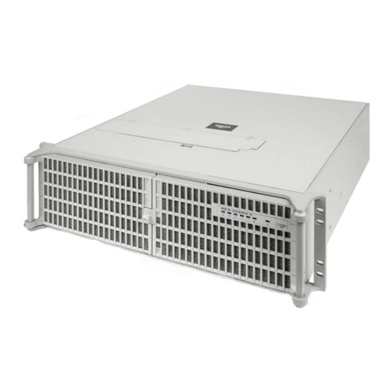
Preface This document, entitled RES-32XR3-S for X8DAL-3/i Installation Manual, pro- vides instructions on how to install, configure, power up, and boot the Themis Rug- ged Enterprise Server RES-32XR3-S for X8DAL-3/i (see Figure 1). Based on two 64-bit Quad-Core 5500-Series or Quad/Six-Core 5600-Series Xeon ®... -
Page 22: Table 1 Res-X2Xr3 20" Chassis Manual Matrix (Ac And Dc Power Supplies)
RES-32XR3-S for X8DAL-3/i Installation Manual Version 1.0 Table 1. RES-x2XR3 20” Chassis Manual Matrix (AC and DC Power Supplies) RES-32XR3 RES-22XR3 RES-12XR3 Manual Motherboard Manual Manual Manual Part Number Part Number Part Number X8DTH-iF Configuration 1 116790-024 1176789-024 X8DTH-6F X8DTi... -
Page 23: Table 2 Res-X2Xr3S / Res-X1Xr3 17" Chassis Manual Matrix (Ac And Dc Power Supplies)
T = Graphics chip; no sound chip w: Not applicable x: i = SATA only 3 = SAS 1.0 6 = SAS 2.0 y: LN4 = Extra gigabit Ethernet controller for two extra ports z: F = IPMI blank = No IPMI Themis Computer... -
Page 24: Table 3 Res-X2Xr3/Fio 16" Chassis Manual Matrix (Ac And Dc Power Supplies)
F = IPMI blank = No IPMI The 3RU-high (5.25”) RES-32XR3-S for X8DAL-3/i has been designed to fit into a standard 19” rack and is provided with rack-mount brackets with handles. Optional rack-mount slides are also available. The RES-32XR3-S for X8DAL-3/i is rugged... - Page 25 Preface tered DIMM memory modules. The RES-32XR3-S for X8DAL-3/i is based on the functionality and capability of the following Intel chipset: • Intel 5500 (Tylersburg) chipset • ICH10R + IOH-24D An overview of RES-32XR3-S for X8DAL-3/i design and specifications is given in Chapter 1, "Overview and Specifications", of this manual.
- Page 26 RES-32XR3-S for X8DAL-3/i Installation Manual Version 1.0 Caution: A caution describes a procedure or action that may result in damage to the equipment. This may involve—but is not restricted to—heavy equipment or sharp objects. To reduce the risk, follow the instructions accompanying this symbol.
-
Page 27: Overview And Specifications
1RES-32XR3-S for X8DAL-3/i Overview and Specifications Overview The RES-32XR3-S for X8DAL-3/i, (see Figure 1-1; a block diagram is given in Figure 1-2, page 1-3), is a rack-mounted system designed for above-average shock ® and vibration environments. The RES-32XR3-S supports dual Intel... -
Page 28: Table 1-1 Res-32Xr3-S For X8Dal-3/I Motherboard Options
Computer, Inc. b—1 in x16 slot. The RES-32XR3-S is designed within a 3RU-high (5.25”) form-factor 17” (43.2 cm) deep and 17” (43.2 cm) wide (which, with mounting brackets, fits a 19”-wide rack). Major features of the RES-32XR3-S for X8DAL-3/i are listed in Table 1-2. -
Page 29: Figure 1-2 X8Dal-3/I Motherboard Block Diagram
CLINK RJ45 82574L Gen1 X4 PORT5 ICH10R PORT1-4 Intel PORT6 RJ45 82574L SATA SATA#1 USB #0/1 COM1 SATA#2 USB #2/3 W83627DHG SATA#3 USB #4/5 COM2 USB #6 SATA#4 SATA#5 SATA#6 PS2 KB/MS Figure 1-2. X8DAL-3/i Motherboard Block Diagram Themis Computer... -
Page 30: Figure 1-3 External Features Of Res-32Xr3-S (Front And Rear)
PCI cards (graphics, RAID, NIC, etc.), two AC power supplies with latch locks and power-cord sockets, and all I/O connectors (see Figure 1-5 on page 1-6). Major internal components of the RES-32XR3-S for X8DAL-3/i can be seen in the Themis Computer... -
Page 31: Figure 1-4 Major Components Of Res-32Xr3-S For X8Dal-3/I (Open Top View)
3 PCI-E 2.0 x4 (in x16 slot 4 PCI-33MHz 5 PCI-33MHz 6 PCI-E 2.0 x16 slot Lithium Battery 120-mm Fan (1 of 2) CD/DVD Front Combo-Drive Storage Drive (1 of 8) Housing Figure 1-4. Major Components of RES-32XR3-S for X8DAL-3/i (Open Top View) Themis Computer... -
Page 32: System Leds And I/O Connectors
Version 1.0 System LEDs and I/O Connectors All RES-32XR3-S system LEDs are located on the front panel (see A, Figure 1-5 on page 1-6); all I/O connectors are located on the rear panel (see B, Figure 1-5). LEDs are described in Table 1-3 on page 1-7; I/O connectors are described in Table 1-4, page 1-8. -
Page 33: Table 1-3 System Leds
The color of the left LED (when facing the port) indicates the LAN connection speed: - Off = 10 MHz LAN1 and LAN2 - Green = 100 MHz - Amber = 1 GHz The right LED, when lit, indicates LAN activity. a—NIC = Network Interface Controller. Themis Computer... -
Page 34: Table 1-4 I/O Connectors
RES-32XR3-S for X8DAL-3/i Installation Manual Version 1.0 Table 1-4. I/O Connectors Connector Description PS/2 Mouse 6-pin mini-DIN (female) connector to attach a PS/2 mouse device. PS/2 Keyboard 6-pin mini-DIN (female) connector to attach a PS/2 keyboard device. 4 4-pin USB connectors on the rear panel. -
Page 35: Chipset Overview
• Two full-width Intel QuickPath interconnect links, up to 6.4 GT/s of data transfer rate in each direction. • Virtualization Technology, Integrated Management Engine supported. • Point-to-point cache coherent interconnect, Fast/narrow unidirectional links, and Concurrent bi-directional traffic. • Error detection via CRC and Error correction via Link level retry. Themis Computer... -
Page 36: Special Features
RES-32XR3-S for X8DAL-3/i Installation Manual Version 1.0 Special Features 1.4.1 Recovery from AC Power Loss BIOS provides a setting for you to determine how the system will respond when AC power is lost and then restored to the system. You can choose for the system to remain powered off (in which case you must press the power switch to turn it back on) or for it to automatically return to a power-on state. -
Page 37: System Resource Alert
When the CPU goes into a suspend state, the chassis power LED will start blinking to indicate that the CPU is in suspend mode. When the user presses any key, the CPU will wake-up and the LED will automatically stop blinking and remain on. 1-11 Themis Computer... -
Page 38: Main Switch Override Mechanism
RES-32XR3-S for X8DAL-3/i Installation Manual Version 1.0 1.6.2 Main Switch Override Mechanism When an ATX power supply is used, the power button can function as a system sus- pend button to make the system enter a SoftOff state. The monitor will be suspended and the hard drive will spin down. -
Page 39: Specifications
Overview and Specifications Specifications Specifications 1.8.1 General Table 1-5 lists general specifications for the RES-32XR3-S. Table 1-5. RES-32XR3-S General Specifications Parameter Description Dimensions 5.25” (3RU) high 17” (43.2 cm) wide (19” rack-mountable) 17” (43.2 cm) deep Weight Approximately 26.5 pounds (12.0 kg), includes 2 CPUs, 6 DIMMs, 2 full-length (up to 12.25”) PCI cards, 1 CD-RW/DVD-... -
Page 40: Electrical
= Not Applicable. 1.8.2.1 System Power The RES-32XR3-S operates with two N+1 redundant AC power supplies of 750- watts capacity each that auto-range single-phase AC input from 100 to 240 VAC (47 to 63 Hertz) sources. Filtered and fused (internal) AC is supplied to each power sup- ply from a rear-mounted power connection. -
Page 41: Output Voltage
1.8.3 Environmental 1.8.3.1 Shock The RES-32XR3-S for X8DAL-3/i is designed to survive an elevated shock envi- ronment. All structural components are welded together, enabling the system to sur- vive a maximum 3-axis shock load of 35G at 25-ms duration. 1.8.3.2 Electrostatic Discharge The RES-32XR3-S for X8DAL-3/i is designed to tolerate electrostatic pulses up to 15 kilovolts (KV) with no impact on system operation. -
Page 42: Figure 1-6 Res-22Xr3 With Front Sound Baffle Installed (Front View)
Figure 1-6. with Front Sound Baffle Installed (Front View) Note: All RES systems are shipped with BIOS fan speed set to the quietest mode. The default fan speed control mode of the RES-32XR3-S for X8DAL-3/i is En- ergy Saving/ES. 1-16... -
Page 43: Figure 1-7 Res-22Xr3 With Front Sound Baffle Installed (Front View)
RES-22XR3 with Front Sound Baffle Installed (Front View) Front Access—Opening the two front doors of the RES-32XR3-S requires remov- ing the front sound baffle. To do this, loosen the two (2) captive knurled Phillips screws holding the baffle to the chassis (see A in Figure 1-8, page 1-18) and remove... - Page 44 Rear Access—Accessing the I/O connectors and PCI card I/O on the rear of the RES-32XR3-S for X8DAL-3/i requires opening the rear sound baffle door. To do this, loosen the four (4) captive knurled Phillips screws A holding the baffle door to the chassis (see A in Figure 1-8) and swing the door downward away from the chas- sis, exposing the rear connectors and PCI cards.
-
Page 45: Packaging And Shipping
AC power cords is 8.8 pounds (4 kg). The approximate weight of a RES-32XR3-S for X8DAL-3/i (loaded with 2 CPUs, 6 DIMMs, 2 storage drives, 2 PCI cards, a CD-RW/DVD-ROM drive, and 2 power supplies) is approximately 26.5 pounds (12.0 kg). -
Page 46: Rack-Mount Slides (Optional)
1.9.2 Rack-Mount Slides (Optional) Rack-Mount Slides can be mounted on each side of the RES-32XR3-S for X8DAL- 3/i for the purpose of sliding the unit in and out of a rack. Mounting slides are optional and can be ordered at the time of purchase. -
Page 47: Installation And Operation
2-9, page 2-11, or page 2-13, respectively. Replacement of motherboard components requires removal of the protective cover. 2.1.1 Remove Protective Top Cover To access a motherboard component, open the RES-32XR3-S for X8DAL-3/i as fol- Themis Computer... - Page 48 1. Loosen the two captive Phillips screws holding the protective top access cover to the rear of the RES-32XR3-S for X8DAL-3/i chassis (see A, Figure 2-1). 2. Both the front and sides of the cover have flat hooks or tabs underneath that fit under slots on the chassis top edges (see B, Figure 2-1).
-
Page 49: Memory Modules
4. Proceed to the appropriate section to install or replace a memory module (page 2-3), PCI card (page 2-7), or lithium battery (page 2-8). 2.1.2 Memory Modules The RES-32XR3-S for X8DAL-3/i supports memory according to Table 2-1. Table 2-1. RES-32XR3-S for X8DAL-3/i Memory Capacity Memory Parameters... -
Page 50: Installation
RES-32XR3-S for X8DAL-3/i Installation Manual Version 1.0 Table 2-4. Memory Population for 2CPUs Installed Memory Population for Optimal Performance -For a motherboard with Two CPUs installed CPU1 (To populate P1-DIMMs) CPU2 (To populate P2-DIMMs) Branch 0 Branch 1 Branch 2... -
Page 51: Figure 2-2 Remove The Air-Flow Deflector Screws
Installation and Operation Installation Procedures 4. If all the memory modules have been replaced in the system, replace the air flow diverter and secure it with the five screws previously removed. Figure 2-2. Remove the Air-Flow Deflector Screws Themis Computer... -
Page 52: Figure 2-3 Memory Module Slot Locations
RES-32XR3-S for X8DAL-3/i Installation Manual Version 1.0 Branch 0 P1 DIMM 1A Branch 1 P1 DIMM 2A Branch 2 P1 DIMM 3A Branch 0 P2 DIMM 1A Branch 1 P2 DIMM 2A Branch 2 P2 DIMM 3A Figure 2-3. Memory Module Slot Locations Press latch downward &... -
Page 53: Pci Cards
Installation and Operation Installation Procedures 2.1.3 PCI Cards RES-32XR3-S for X8DAL-3/i supports six PCI/PCI-Express slots. (see Figure 2-5). Slot 1 Slot 2 PCI-E 1.0 x4 in x8 slot Slot 3 PCI-E 2.0 x4 in x16 slot Slot 4 PCI 33MHz Slot 5 PCI 33MHz Slot 6 PCI-Express 2.0 in x16 slot... -
Page 54: Lithium Battery
7. Attach any internal I/O cables to the installed PCI cards, and carefully fold and tuck any exposed ribbon cables into the cabinet. 8. If you have no further installations to perform, close the RES-32XR3-S for X8DAL-3/i chassis by refastening the top cover removed in Section 2.1.1, “Remove Protective Top Cover,”... -
Page 55: Installing A Lithium Battery
2. Carefully press down on the battery until it clicks firmly into place. 2.1.5 SAS/SATA Storage Drive Perform the following steps to remove and install a SATA storage drive. The front doors of the RES-32XR3-S for X8DAL-3/i must be unlocked and opened to access the storage drives (see Figure 2-8). Knurled Screw Figure 2-8. -
Page 56: Storage Drive Removal
Drive Release Drive Lock Button (one per drive) Figure 2-9. Unlocking the RES-32XR3-S for X8DAL-3/i Storage Drives (Front Doors Removed) 2.1.5.2 Storage Drive Removal After opening the front doors, perform the following steps to remove and install a storage drive: 1. -
Page 57: Storage Drive Installation
3. Push the drive toward the rear (DO NOT CLOSE the latch handle while push- ing) until the drive is flush with the front of the chassis. The handle will swing closed when it comes into contact with the RES-32XR3-S for X8DAL-3/i chassis. -
Page 58: Removing And Installing A 120-Mm Fan
Version 1.0 which can be “hot-swapped” in the field in the event of a fan failure. Note: Since RES-32XR3-S for X8DAL-3/i fans are “hot-swappable”, it is not necessary to turn off system power in order to remove and replace a fan, 2.1.6.1 Removing and Installing a 120-mm Fan... -
Page 59: Power Supply
Push right to release power supply (for power supply locking bracket) Power Supply Locking Lever Phillips Screw Hole for knurled captive screw on power supply locking bracket Extraction Handle Figure 2-12. The RES-32XR3-S for X8DAL-3/i Power Supply Locking Mechanism 2-13 Themis Computer... -
Page 60: Installing A Power Supply
RES-32XR3-S for X8DAL-3/i Installation Manual Version 1.0 2. Put the right index finger on the power supply extraction handle and the right thumb on the left side of the power supply locking lever. 3. Squeeze the locking lever toward the pull handle and firmly pull the power supply from the chassis. -
Page 61: Rack Mounts
The rack-mount brackets (flanges) are used to secure the chassis to the 19” rack (see Figure 2-13). Handles are used to pull the RES-32XR3-S for X8DAL-3/i from the rack when rack-mount slides have been installed on the sides of the chassis (see fol- lowing section). -
Page 62: Operation
Operation 2.3.1 Plugging in the AC Power Cords Before powering on the RES-32XR3-S for X8DAL-3/i, plug in the AC power cords as fol- lows: 1. On the rear of the RES-32XR3-S for X8DAL-3/i, plug an AC power cord (shipped with unit) into the AC power socket on each power supply (see Fig- ure 2-14). -
Page 63: Getting Started
Installation and Operation Operation 2. On the front of the RES-32XR3-S for X8DAL-3/i push the system power on/off button (see Figure 2-15). This will cause the system POWER LED to light (green). Power LED System Power On/Off Button Figure 2-15. - Page 64 RES-32XR3-S for X8DAL-3/i Installation Manual Version 1.0 1. To turn the RES-32XR3-S for X8DAL-3/i power off, press and hold the sys- tem power on/off button (see Figure 2-15, page 2-17) for at least four (4) sec- onds. This will shut down the system and turn off the POWER LED.
-
Page 65: Bios Setup Utility
The right frame displays the key legend. Above the key legend is an area reserved for a text message. When an option is selected in the left frame, it is highlighted in white. Often a text message will accompany it. Themis Computer... -
Page 66: How To Change The Configuration Data
RES-32XR3-S for X8DAL-3/i Installation Manual Version 1.0 Note: The AMI BIOS has default text messages built in. Themis retains the op- tion to include, omit, or change any of these text messages. The AMI BIOS Setup Utility uses a key-based navigation system called “hot keys”. -
Page 67: Main Setup
<Enter>. Press the <Tab> key to move between fields. The date must be entered in Day MM/DD/YY format. The time is entered in HH:MM:SS format. Note: The time is in the 24-hour format. For example, 5:30 P.M. appears as 17:30:00. Themis Computer... -
Page 68: Supermicro X8Dal Motherboard
RES-32XR3-S for X8DAL-3/i Installation Manual Version 1.0 3.2.2 Supermicro X8DAL Motherboard • Version: This item displays the BIOS revision used in your system. • Build Date: This item displays the date when this BIOS was completed. 3.2.3 Processor The AMI BIOS will automatically display the status of the processor used in your system: •... -
Page 69: Boot Features
If this item is set to disabled, the ROM BIOS of the host adaptors will not capture Interrupt 19, and the drives attached to these adaptors will not func- tion as bootable devices. The options are Enabled and Disabled. Themis Computer... -
Page 70: Power Configuration
RES-32XR3-S for X8DAL-3/i Installation Manual Version 1.0 3.3.2 Power Configuration 3.3.2.1 Watch Dog Function If enabled, the Watch Dog Timer will allow the system to reboot when it is inactive for more than 5 minutes. The options are Enabled and Disabled. -
Page 71: Mps And Acpi Madt Ordering
The default is Enabled. (Refer to Intel and Microsoft Web Sites for more information.) 3.3.3.7 Simultaneous Multi-Threading (Available when supported by the CPU) Set to Enabled to use the Simultaneous Multi-Threading Technology to enhance Themis Computer... -
Page 72: Active Processor Cores
RES-32XR3-S for X8DAL-3/i Installation Manual Version 1.0 CPU performance. The options are Disabled and Enabled. 3.3.3.8 Active Processor Cores Set to Enabled to use a processor's Second Core and beyond. (Please refer to Intel's web site for more information.) The options are All, 1 and 2. -
Page 73: C3 Auto Demotion (Available When The C-State Tech Is Enabled)
The options are Disabled and Enabled. Memory Frequency This feature forces a DDR3 frequency slower than what the system has detected. The available options are Auto, Force DDR-800, Force DDR-1066, and Force DDR-1333. Memory Mode The options are Independent, Channel Mirror, and Lockstep. Themis Computer... -
Page 74: Northbridge Chipset Configuration
RES-32XR3-S for X8DAL-3/i Installation Manual Version 1.0 Independent - All DIMMs are available to the operating system. Channel Mirror - The motherboard maintains two identical copies of all data in memory for redundancy. Lockstep - The motherboard uses two areas of memory to run the same set of opera- tions in parallel. -
Page 75: Dca Prefetch Delay
3.3.6.1 USB Functions This feature allows the user to decide the number of onboard USB ports to be enabled. The Options are: Disabled, and Enabled. (If this item is set to Enabled, USB 2.0 Controller will be enabled.) 3-11 Themis Computer... -
Page 76: Legacy Usb Support
RES-32XR3-S for X8DAL-3/i Installation Manual Version 1.0 3.3.6.2 Legacy USB Support Select Enabled to use Legacy USB devices. If this item is set to Auto, Legacy USB support will be automatically enabled if a legacy USB device is installed on the motherboard, and vice versa. -
Page 77: Sata#2 Configuration (This Feature Is Available When The Option-Ide Is Selected For Sata#1)
<Enter> to activate the following submenu screen for detailed options of these items. Set the correct configurations accordingly. The items included in the submenu are: Type Select the type of device connected to the system. The options are Not Installed, Auto, CD/DVD and ARMD. LBA/Large Mode 3-13 Themis Computer... -
Page 78: Pio Mode
RES-32XR3-S for X8DAL-3/i Installation Manual Version 1.0 LBA (Logical Block Addressing) is a method of addressing data on a storage drive. In the LBA mode, the maximum drive capacity is 137 GB. For drive capacities over 137 GB, your system must be equipped with a 48-bit LBA mode addressing. If not, contact your manufacturer or install an ATA/133 IDE controller card that supports 48-bit LBA mode. - Page 79 Select Auto to allow the AMI BIOS to automatically detect Select Disabled to prevent the AMI BIOS from using the S.M.A.R.T. Select Enabled to allow the AMI BIOS to use the S.M.A.R.T. to support hard drive disk. The options are Disabled, Enabled, and Auto. 3-15 Themis Computer...
-
Page 80: Pci/Pnp Configuration
RES-32XR3-S for X8DAL-3/i Installation Manual Version 1.0 32Bit Data Transfer Select Enable to enable the function of 32-bit IDE data transfer. The options are Enabled and Disabled. 3.3.8 PCI/PnP Configuration 3.3.8.1 Clear NVRAM This feature clears the NVRAM during system boot. The options are No and Yes. -
Page 81: Onboard Lan Option Rom Select
2F8/IRQ3, 3E8/IRQ4, and 2E8/IRQ3. 3.3.10 Remote Access Configuration 3.3.10.1 Remote Access This allows the user to enable the Remote Access feature. The options are Enabled and Disabled. If Remote Access is set to Enabled, the following items will display: 3-17 Themis Computer... -
Page 82: Serial Port Number
RES-32XR3-S for X8DAL-3/i Installation Manual Version 1.0 3.3.10.2 Serial Port Number This feature allows the user to decide which serial port to be used for Console Redi- rection. The options are COM 1 and COM 2. Base Address, IRQ This item displays the based address and IRQ of the serial port specified above. The default setting is 2F8h, 3. -
Page 83: Sredir Memory Display Delay
In both the alarms above, please take immediate action as shown below. 3.3.11.2 CPU 1 Temperature/CPU 2 Temperature/IOH Tempera- ture/System Temperature This feature displays current temperature readings for the CPUs and the System. The following items will be displayed for your reference only: 3-19 Themis Computer... - Page 84 RES-32XR3-S for X8DAL-3/i Installation Manual Version 1.0 CPU 1 Temperature/ CPU 2 Temperature The CPU Temperature feature will display the CPU temperature status as detected by the BIOS: • Low – This level is considered as the ‘normal’ operating state. The CPU tem- perature is well below the CPU ‘Temperature Tolerance’.
-
Page 85: Voltage Readings
The following voltage readings will be displayed. Vcore1, Vcore2, 1.5V, 5VDD, 5VSB, 12V, -12V, 3.3Vcc, 3.3Vsb, and VBAT and Vtt. 3.3.12 ACPI Configuration Use this feature to configure Advanced Configuration and Power Interface (ACPI) power management settings for your system. 3-21 Themis Computer... -
Page 86: High Precision Event Timer
RES-32XR3-S for X8DAL-3/i Installation Manual Version 1.0 3.3.12.1 High Precision Event Timer Select Enabled to activate the High Precision Event Timer (HPET) that produces periodic interrupts at a much higher frequency than a Real-time Clock (RTC) does in synchronizing multimedia streams, providing smooth playback and reducing the dependency on other timestamp calculation devices, such as an x86 RDTSC Instruc- tion embedded in the CPU. -
Page 87: Acpi Version Features
3.3.13.4 PCIE Error Log Use this option to enable PCI-Exp. error (PERR) logging. The options are Yes and 3.3.13.5 Memory Error Log Select Yes to activate and display ECC Memory Error event log. The options are Yes and No. 3-23 Themis Computer... -
Page 88: Security Settings
RES-32XR3-S for X8DAL-3/i Installation Manual Version 1.0 Security Settings The AMI BIOS provides a Supervisor and a User password. If you use both pass- words, the Supervisor password must be set first. Figure 3-3. Security Settings 3.4.1 Supervisor Password This item indicates if a Supervisor password has been entered for the system. “Not Installed”... -
Page 89: User Access Level (Available When Supervisor Password Is Set As Above)
Boot Sector Virus Protection When Enabled, the AMI BIOS displays a warning when any program (or virus) issues a Format command or attempts to write to the boot sector of the storage drive. The options are Enabled and Disabled. 3-25 Themis Computer... -
Page 90: Boot Configuration
RES-32XR3-S for X8DAL-3/i Installation Manual Version 1.0 Boot Configuration Figure 3-4. Boot Settings Use this feature to configure boot settings. 3.5.1 Boot Device Priority This feature allows the user to specify the sequence of priority for the Boot Device. The settings are 1st boot device, 2nd boot device, 3rd boot device, 4th boot device, 5th boot device and Disabled. -
Page 91: Removable Drives
This feature allows the user to specify the boot sequence from available CD/DVD Drives. 3.5.4.1 Retry Boot Devices If this feature is enabled, the system will continue to search for the next boot device if the current boot device is not available. The options are Enabled, and Disabled. 3-27 Themis Computer... -
Page 92: Exit Options
RES-32XR3-S for X8DAL-3/i Installation Manual Version 1.0 Exit Options Select the Exit tab from the AMI BIOS Setup Utility screen to enter the Exit Setup screen. Figure 3-5. Exit Options 3.6.1 Save Changes and Exit After configuring the Setup settings, select this option to save the changes and exit the BIOS Setup Utility and reboot the computer, so the new system configuration parameters can take effect. -
Page 93: Discard Changes
Flashing the wrong BIOS can cause irreparable damage to the system. In no event shall Themis be liable for direct, indirect, special, incidental, or consequential dam- ages arising from a BIOS update. If you need to update the BIOS, do not shut down or reset the system while the BIOS is updating. -
Page 94: Boot Sector Recovery From A Usb Device
RES-32XR3-S for X8DAL-3/i Installation Manual Version 1.0 tinue with system initialization and complete the bootup process. Note: BIOS Recovery described below is used when the main BIOS block crash- es. However, when the BIOS Boot sector crashes, you will need to send the moth- erboard back to Supermicro for RMA repairs. -
Page 95: Requirements
• Data Bits: 8 • Parity: None • Stop Bit: 1 • Flow Control: None 4. Power on your system and click the <Connect> button in the Hyper Terminal. The terminal screen will display the following messages. 3-31 Themis Computer... -
Page 96: Figure 3-6 Ami_Flsh Hyperterminal
RES-32XR3-S for X8DAL-3/i Installation Manual Version 1.0 5. Follow the instructions given on the screen to update the BIOS. These instruc- tions are also shown below. a. At the prompt, press the <SpaceBar> to update the BIOS. b. When asked to confirm BIOS updating, press <y> to confirm BIOS up- dates. -
Page 97: Figure 3-7 Rom File Extraction
VT-100 and XModem protocols, including protocols designed for GNU/LINUX & BSD operating systems such as minicom. It is recommended that the terminal program be configured to use the 'CR/LF' style of line termina- tion. 3-33 Themis Computer... -
Page 98: Bios Error Beep Codes
RES-32XR3-S for X8DAL-3/i Installation Manual Version 1.0 BIOS Error Beep Codes During the POST (Power-On Self-Test) routines, which are performed each time the system is powered on, errors may occur. Non-fatal errors are those which, in most cases, allow the system to continue the boot-up process. - Page 99 BIOS Setup Utility BIOS Error Beep Codes 3-35 Themis Computer...
- Page 100 RES-32XR3-S for X8DAL-3/i Installation Manual Version 1.0 3-36 Themis Computer...
-
Page 101: Appendix A. Connector Pinouts
I/O panel of the RES-32XR3-S for X8DAL-3/i. PS/2 Keyboard and Mouse The RES-32XR3-S provides a 6-pin female mini-DIN connector for the PS/2 key- board, and another for the PS/2 mouse. Signals for both connectors are defined in Table A-1. -
Page 102: Usb Ports
Version 1.0 USB Ports The RES-32XR3-S supports four USB port connectors (see Figure A-1 for a connec- tor pinout), USB 0 thru USB 3, on the rear I/O panel. An additional 2 USB internal headers can be accessed directly from the motherboard for a total of 8 USB ports. -
Page 103: Gigabit Ethernet Lan Ports
2 channels of independent stereo sound outputs. The multiple_streaming outputs are routed through the motherboard stereo out for front L&R, rear L&R, center, and sub- woofer speakers. Use the software included in the CD-ROM that came with your RES-32XR3-S to Themis Computer... - Page 104 RES-32XR3-S for X8DAL-3/i Installation Manual Version 1.0 enable this function. The RES-32XR3-S supports six sub-miniature (3.5-mm diameter) audio ports: Orange: Blue: Line-in CEN/LFE Black: Green: Front Back Surround Grey: Side Surround Pink: Mic-In Figure A-4. High Definition Audio Ports The microphone jack will support most types (dynamic, condenser, etc.) of micro- phones now on the market.
-
Page 105: Appendix B. Rack-Mount Slide Installation
An optional set of two rack-mount slides (left side and right side) is available for all RES-32 systems, and should be ordered at the time of purchase. The RES-32XR3-S for X8DAL-3/i chassis contains five threaded screw holes on each side to accommo- date #8-32 size screws (included with the rack-mount slide kit);... - Page 106 Two rear (long) slide brackets e. Assorted screws, washers, and nuts Follow these steps to install a steel rack-mount slide to the RES-32XR3-S for X8DAL-3/i chassis: 1. Attach the inside slide section (see Figure B-2 on page B-3) to both sides of the RES-32XR3-S for X8DAL-3/i chassis using four #8-32 screws per side.
- Page 107 (included in slide kit) Attach both inside slide sections to the left and right sides of the RES-32XR3-S chassis with #8-32 screws (included in slide kit) Figure B-1. RES-32XR3-S for X8DAL-3/i Rack-Mount Slide Installation...
- Page 108 RES-32XR3-S for X8DAL-3/i Installation Manual Version 1.0 Themis Computer...
-
Page 109: Appendix C. Red Hat Enterprise Linux 5 Installation
Welcome to the Red Hat ® Enterprise Linux ® Installation Guide. This guide contains useful information to assist you during the installation of Red Hat Enterprise Linux via DVD device, from fundamental concepts such as installation preparation to the step-by-step installation procedure. Themis Computer... -
Page 110: Installation
RES-32XR3-S for X8DAL-3/i Installation Manual Version 1.0 Installation C.2.1 Step 1. Figure C-1. Power On after Linux DVD is Inserted into Drive Step 1: Insert the Redhat Enterprise Linux 5 DVD and Power on the system; you will see the first installation screen with a boot prompt, press “ENTER” to begin installation (see Figure C-1 on page C-2). -
Page 111: Figure C-3 Welcome Screen
The installation program tries to define the appropriate time zone based on what you specify on this screen. Once you have made the language selection, click Next to continue. (see Figure C-4 on page C-3) Themis Computer... -
Page 112: Figure C-5 Selecting Layout Type
RES-32XR3-S for X8DAL-3/i Installation Manual Version 1.0 C.2.5 Step 5 Figure C-5. Selecting Layout Type Step 5: Using your mouse, select the correct layout type (for example, U.S. English) for the keyboard you would prefer to use for the installation and as the system default. -
Page 113: Figure C-7 Partitioning
You can configure an iSCSI target for installation, or disable a dmraid device from this screen by clicking on the 'Advanced storage configuration' button (see Figure C-7 on page C-5). Click Next to continue. Themis Computer... -
Page 114: Figure C-8 Reviewing Option
RES-32XR3-S for X8DAL-3/i Installation Manual Version 1.0 C.2.8 Step 8 Figure C-8. Reviewing Option Step 8: Create default layout allows you to have some control concerning what data is removed (if any) from your system. Your options are: • Remove all partitions on selected drives and create default layout — select this option to remove all partitions on your hard drive(s) (this includes partitions created by other operating systems such as Windows VFAT or NTFS partitions). -
Page 115: Figure C-9 Creating A Custom Layout
Red Hat Enterprise Linux. This is done by defining mount points for one or more partitions in which Red Hat Enterprise Linux is installed. You may also need to create and/or delete partitions at this time (see Figure C-9 on page C-7). Click Next. Themis Computer... -
Page 116: Figure C-10 Setting Up Boot Loader
RES-32XR3-S for X8DAL-3/i Installation Manual Version 1.0 C.2.10 Step 10 Figure C-10. Setting Up Boot Loader Step 10: Once you have configured your partitions, set up a boot loader. If you select “No Boot Loader will be Installed,” you’ll need to use a third-party boot loader such as Partition Magic or Microsoft’s TLDR. -
Page 117: Figure C-11 Master Boot Record (Mbr
In this case, your other boot loader takes control first. You can then configure that boot loader to start GRUB, which then boots Red Hat Enterprise Linux. If your system only uses Red Hat Enterprise Linux, you should choose the MBR. Themis Computer... -
Page 118: Figure C-12 Network Devices List
RES-32XR3-S for X8DAL-3/i Installation Manual Version 1.0 Click the Change Drive Order button if you would like to rearrange the drive order or if your BIOS does not return the correct drive order. Changing the drive order may be useful if you have multiple SCSI adapters, or both SCSI and IDE adapters, and you want to boot from the SCSI device. -
Page 119: Figure C-13 Edit Interface Pop-Up Screen
If you select Activate on boot, your network interface is started when you boot (see Figure C-13 on page C-11). If you do not have DHCP client access or you are unsure what to provide here, please contact your network administrator. Click OK. C-11 Themis Computer... -
Page 120: Figure C-14 Selecting Time Zone
RES-32XR3-S for X8DAL-3/i Installation Manual Version 1.0 C.2.14 Step 14 Figure C-14. Selecting Time Zone Step 14: Set your time zone by selecting the city closest to your computer's physical location. Click on the map to zoom in to a particular geographical region of the world (see Figure C-14 on page C-12). -
Page 121: Figure C-15 Setting Up Root Account And Password
Your root account is similar to the administrator account used on Windows NT machines. The root account is used to install packages, upgrade RPMs, and perform most system maintenance. Logging in as root gives you complete control over your system (see Figure C-15 on page C-13). Click Next. C-13 Themis Computer... -
Page 122: Figure C-16 Package Installation Default Screen
RES-32XR3-S for X8DAL-3/i Installation Manual Version 1.0 C.2.16 Step 16 Figure C-16. Package Installation Default Screen Now that you have made most of the choices for your installation, you are Step 16: ready to confirm the default package selection or customize packages for your sys- tem. -
Page 123: Figure C-17 Optional Packages
Optional packages to view which packages are installed by default, and to add or remove optional packages from that group (see Figure C-17 on page C-15). If there are no optional components this button will be disabled. Click Next. C-15 Themis Computer... -
Page 124: Figure C-18 Option To Review Or Continue
RES-32XR3-S for X8DAL-3/i Installation Manual Version 1.0 C.2.18 Step 18 Figure C-18. Option to Review or Continue Step 18: Once you have selected the package groups of your choice, you get one last chance to go back before starting the installation process. Click Next if you’re happy with your choices, or click Back to make changes (see Figure C-18 on page C-16). -
Page 125: Figure C-20 Installation Is Complete
• Do nothing — after the boot loader's time-out period, (by default, five seconds) the boot loader automatically boots the default boot entry. Do whatever is appropriate to boot Red Hat Enterprise Linux. One or more screens of messages should scroll by. C-17 Themis Computer... -
Page 126: Figure C-21 Login Screen
RES-32XR3-S for X8DAL-3/i Installation Manual Version 1.0 C.2.21 Step 21 Figure C-21. Login Screen Eventually, a prompt or a GUI login screen appears (if you installed Step 21: login: the X Window System and chose to start X automatically). (see Figure C-21 on page C-18). -
Page 127: Appendix D. Optional Remote On/Off Switch
Remote On/Off Configuration Customers interested in installing an optional switch from which to remotely turn the RES-32XR3-S for X8DAL-3/i on or off are able to order a Remote On/Off Switch module that is easily installed in an available storage-drive bay (see Figure D-1, which shows the Remote On/Off Switch installed in an RES-32XR3/FIO sys- tem). -
Page 128: Remote On-Only Configuration
When operational, if the RES-32XR3-S for X8DAL-3/i is turned OFF, pressing the remote switch ON will turn the system on. If the RES-32XR3-S for X8DAL-3/i is turned ON, pressing the switch OFF for less than 4 seconds will gracefully shut down the system through the BIOS; pressing the switch OFF for 4 seconds or more results in a “hard”... -
Page 129: Appendix E. Re-Packing Instructions
Re-Packing Instructions Re-Packaging for Shipment If it becomes necessary to return equipment to Themis Computer, it is very impor- tant that the equipment be shipped in packaging that provides adequate protection against crushing and moisture invasion. The original packaging is best for this pur- pose, provided the packaging is retained in serviceable condition. -
Page 130: Instructions For Re-Packing
RES-32XR3-S for X8DAL-3/i Installation Manual Version 1.0 side with the plastic membrane is against the equipment. Top Layer Membrane Bottom Layer Packing Container Figure E-1. Packaging Components Instructions for Re-Packing Re-assemble the packing material about the equipment in accordance with the fol- lowing instructions: (See Figure E-2. -
Page 131: Figure E-2 Order Of Assembly
• Seal the top of the box with strong packing tape, wrapping the tape completely around the box, both lengthwise, and crosswise. • Prepare for shipment in accordance with the instructions received from Themis Computer. Figure E-2. - Page 132 RES-32XR3-S for X8DAL-3/i Installation Manual Version 1.0 Themis Computer...
- Page 133 2-1 Configuration One Table Chipset 1-2 Memory 1-2 Processors 1-2 I/O Connectors Configuration, system 2-17 Ethernet LAN Port 1-8 CPU 1-1 PS/2 keyboard 1-8 PS/2 mouse 1-8 Serial Ports 1-8 USB Serial Ports 1-8 Dimensions, chassis 1-2 Index-1 Themis Computer...
- Page 134 I/O faceplates 1-4 Notes xxi ICH1OR + IOH-24D xxi Installation procedures 2-1 installing rack-mount slides B-1 Opening the RES-32XR3-S Front Doors 2-9 memory modules 2-4 Operating temperature 1-2 PCI cards 2-7 Optional Remote On/Off Switch D-1 Instructions for Re-Packing E-2...
- Page 135 Re-Packing Instructions E-1 Noise 1-15 RES Series Models Packaging and Shipping 1-19 Approximate Weights 1-20 Plug Type 1-14 RES-32XR3-S for X8DAL-3/-i 1-1 Power Factor 1-14 RES-32XR3-S General Specifications 1-13 Relative Humidity 1-13 RES-32XR3-S Major Features 1-2 Shock 1-15 reset switch 1-4 Temperature 1-13 RES-x2XR3 17"...
- Page 136 RES-32XR3-S for X8DAL-3/i Installation Manual Version 1.0 Index-4 Themis Computer...
- Page 137 Place Stamp Here Themis Computer 47200 Bayside Parkway Fremont, CA 94538 Attn: Publications Department Fold here; tape at top to seal...
- Page 138 Reader Comment Card We welcome your comments and suggestions to help improve the RES-32XR3-S for X8DAL-3/i Installation Manual. Please take time to let us know what you think about this manual. • Information provided in the manual was complete. Agree___...
Need help?
Do you have a question about the RES-32XR3-S and is the answer not in the manual?
Questions and answers