
Related Manuals for Themis RES-12XR3


Summary of Contents for Themis RES-12XR3
- Page 1 Installation Installation Manual Manual 1RU 19 ” Rac k- M ount Rugged Enter prise Ser ver with X8DTU - F M other board Configuration / Two Q uad - Core 550 0 or Q uad / Six- Core 56 0 0 Xeon CPUs...
- Page 3 RES-12XR3 Installation Manual - Configuration 7* Version 1.1— March 2011 * SuperMicro Motherboard X8DTU-F Themis Computer—Americas and Pacific Rim Themis Computer—Rest of World 47200 Bayside Parkway 5 Rue Irene Joliot-Curie Fremont, CA 94538 38320 Eybens, France Phone (510) 252-0870 Phone +33 476 14 77 80...
-
Page 4: Safety Precautions
Themis Computer assumes no responsibility for inaccuracies. Themis Computer retains the right to make changes to this publication at any time without prior notice. Themis Computer does not assume any liability arising from the application or use of this publication or the product(s) described herein. - Page 5 RES-12XR3 Installation Manual - Configuration 7 Version Revision History Version 1.1 ..................March 2011 • Added RES Matrix tables 2&3 to the Preface. • Updated maxium memory capacity throughout the manual related to the current revision of the X8DTU-F motherboard. • Updated information in Table 1-2, page 1-2 & Table 1-7, page 1-15.
-
Page 6: Safety Instructions
In these cases, the device must be shut down and secured against unintentional operation. • Repairs may only be carried out by a person authorized by Themis Computer. • The device may only be opened for the installation and removal of extension... -
Page 7: Grounding Methods
RES-12XR3 Installation Manual - Configuration 7 Safety Instructions and the lithium battery—all in accordance with the instructions given in this manual. • If extensions are made to the device, the legal stipulations and the device spec- ifications must be observed. - Page 8 RES-12XR3 Installation Manual - Configuration 7 Version 1.1 2. Use anti-static mats, heel straps, or air ionizers to give added protection. 3. Handle electrostatic-sensitive components, boards, and assemblies by the case or the PCB edge. 4. Avoid contact with pins, leads, or circuitry.
-
Page 9: Table Of Contents
1.8.2.1 System Power ................1-15 1.8.2.2 Output Voltage ................1-16 1.8.3 Environmental ..................1-16 1.8.3.1 Shock ..................1-16 1.8.3.2 Electrostatic Discharge ............. 1-16 1.8.3.3 Noise ..................1-16 1.9 Packaging and Shipping ..................1-17 1.9.1 Accessory Kit ................... 1-17 Themis Computer... - Page 10 2.1.4.1 Removing the Lithium Battery ..........2-11 2.1.4.2 Installing a Lithium Battery ............2-12 2.1.5 SATA II Storage Drive ................2-12 2.1.5.1 Opening the RES-12XR3 Front Doors ........2-13 2.1.5.2 Storage-Drive Removal ............2-13 2.1.5.3 Storage Drive Installation ............2-14 2.1.6 Hot-Swappable 38-mm Fan ..............
- Page 11 (Available when supported by the CPU) ........3-8 3.3.3.9 Intel AES-NI ................3-8 3.3.3.10 Simultaneous Multi-Threading (Available when supported by the CPU) ........3-8 3.3.3.11 Active Processor Cores ............... 3-9 3.3.3.12 Intel EIST Technology ..............3-9 3.3.3.13 Intel® TurboMode Technology ..........3-9 Themis Computer...
- Page 12 RES-12XR3 Installation Manual - Configuration 7 Version 1.1 3.3.3.14 C1E Support ................3-9 3.3.3.15 Intel® C-STATE Tech ..............3-9 3.3.3.16 C-State package limit setting ............3-9 3.3.3.17 C1 Auto Demotion ..............3-9 3.3.3.18 C3 Auto Demotion ..............3-9 3.3.3.19 ACPI T State ................3-10 3.3.4 Advanced Chipset Control ...............
- Page 13 3.3.10.8 WHEA Support ................. 3-24 3.3.11 IPMI Configuration .................. 3-24 3.3.11.1 IPMI Firmware Version ............3-24 3.3.11.2 Status of BMC Working ............3-24 3.3.12 View BMC System Event Log ..............3-25 3.3.12.1 Clear BMC System Event Log ..........3-25 Themis Computer...
- Page 14 RES-12XR3 Installation Manual - Configuration 7 Version 1.1 3.3.13 Set LAN Configuration ................3-26 3.3.14 Event Log Configuration ................. 3-27 3.3.14.1 View Event Log ................ 3-27 3.3.14.2 Mark All Events as Read ............3-27 3.3.14.3 Clear Event Log ................ 3-27 3.3.14.4 PCIE ErrorLog ................
- Page 15 D.2 Remote On-Only Configuration ................D-2 D.3 Ordering the Remote On/Off Switch ..............D-2 Appendix E. Re-Packing Instructions ................E-1 E.1 Re-Packaging for Shipment ...................E-1 E.2 Packing Components .....................E-1 E.3 Instructions for Re-Packing ...................E-2 Index ........................ Index-1 Reader Comment Card xiii Themis Computer...
- Page 16 RES-12XR3 Installation Manual - Configuration 7 Version 1.1 Themis Computer...
- Page 17 External Features of the RES-12XR3 (X8DTU-F Motherboard)....1-2 Figure 1-3 X8DTU-F Motherboard Block Diagram ............1-3 Figure 1-4 Open Top View of the RES-12XR3—Air Flow Diverter Removed ....1-5 Figure 1-5 RES-12XR3 System LEDs and I/O Connectors (X8DTU-F Motherboard)..1-9 Figure 2-1 Remove the RES-12XR3 Protective Access Cover.........
- Page 18 Right Rack-Mount Bracket ................2-19 Figure 2-19 AC Power Socket and LED on the RES-12XR3 Rear........2-20 Figure 2-20 System Power Button and LED on the RES-12XR3 Front ......2-20 Figure 3-1 Main BIOS Setup Screen ................. 3-3 Figure 3-2 Advanced Settings ...................
- Page 19 Table 3 Front I/O 16”-Deep Chassis Manual Matrix............xx Table 1-1 RES-12XR3 Motherboard Options—Configuration 7 ........1-2 Table 1-2 Major Features of RES-12XR3—Configuration 7 ......... 1-4 Table 1-3 Power Supply LED behavior ................ 1-10 Table 1-4 System LEDs ....................1-11 Table 1-5 Rear-Panel I/O Connectors ................
- Page 20 Version 1.1 Table 2-3 RES-12XR3 Optimal Memory Population (CPU2 Installed)......2-3 Table 2-4 RES-12XR3 Optimal Memory Population (CPU1/CPU2 Installed) ....2-3 Table 2-5 1RU Riser Cards Available for the X8DTU-F Motherboard ......2-8 Table 3-1 PIO Mode Select Options ................3-16 Table 3-2 DMA Mode Select Options ................
-
Page 21: Preface
Preface This document, entitled RES-12XR3 Installation Manual—Configuration 7, pro- vides instructions on how to install, configure, power up, and boot the Themis Rug- ged Enterprise Server RES-12XR3 Configuration 7 (see Figure 1 below), which is ® ™ ® based on two 64-bit Intel... -
Page 22: Table 1 Res-X2Xr3 20"-Deep Chassis Manual Matrix
RES-12XR3 Installation Manual - Configuration 7 Version 1.1 Table 1. RES-x2XR3 20”-Deep Chassis Manual Matrix RES-22XR3 RES-32XR3 RES-22XR3 RES-12XR3 with Riser Category Motherboard Manual Manual Manual Manual kets Part Number Part Number Part Number Part Number X8DTH-iF Configuration 1 116790-024... -
Page 23: Table 2 Res-X2Xr3S / Res-X1Xr3 17"-Deep Chassis Manual Matrix
LN4 = Extra gigabit Ethernet controller for two extra ports z: F = IPMI blank = No IPMI a—The 17”-deep RES XR3 chassis actually measures 17.07” deep, but for simplicity will continue to be referred to as being 17” deep through- out these manuals. Themis Computer... -
Page 24: Figure 2 Front View Of A Standard Rear-I/O Res-32 Chassis (Doors Removed)
RES-12XR3 Installation Manual - Configuration 7 Version 1.1 A matrix describing RES chassis configured for front-I/O connector and front-PCI card access in a 16”-deep chassis is given in Table 3. This chassis design makes it more convenient to install cables to the system and demands no access to the rear of the chassis except to replace a fan. -
Page 25: Figure 3 Rear View Of A Standard Rear-I/O Res-32 Chassis
Preface Figure 3. Rear View of a Standard Rear-I/O RES-32 Chassis Figure 4. Front View of a Front-I/O RES-32 Chassis Figure 5. Rear View of a Front-I/O RES-32 Chassis Themis Computer... - Page 26 RES-12XR3 Installation Manual - Configuration 7 Version 1.1 The 1RU-high (1.75”) RES-12XR3 has been designed to fit into a standard 19” rack and is provided with rack-mount brackets with handles. Optional rack-mount slides are also available. The RES-12XR3 is rugged enough to withstand extreme shock (up to 35G), temperature, and EMI as that associated with such demanding markets as the military, aerospace, and telecommunications industries.
- Page 27 To reduce the risk, follow the in- structions accompanying this symbol. Sidebar: A “sidebar” adds detail to the section within which it is placed, but is not absolutely vital to the description or procedure of the section. xxiii Themis Computer...
- Page 28 RES-12XR3 Installation Manual - Configuration 7 Version 1.1 xxiv Themis Computer...
-
Page 29: Overview And Specifications
Chapter Overview and Specifications Overview The RES-12XR3 Configuration 7 (see Figure 1-1 below; a block diagram is given in Figure 1-3, page 1-3) is a rack-mounted high-performance system designed spe- cifically for above-average shock and vibration environments. The RES-12XR3 sup- ports two Intel®... -
Page 30: Figure 1-2 External Features Of The Res-12Xr3 (X8Dtu-F Motherboard)
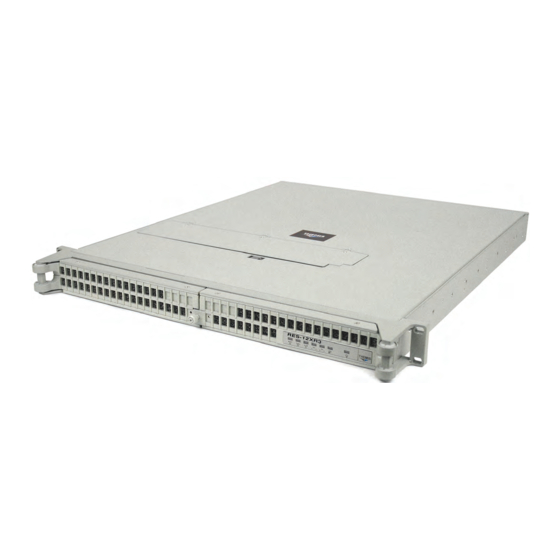
The RES-12XR3 is designed within a 1RU-high (1.75”) form-factor 20” (50.8 cm) deep and 17” (43.2 cm) wide (which, with mounting brackets, fits a 19”-wide rack; see Figure 1-2). Major features of the RES-12XR3 are described in Table 1-2, page 1-4. CD-RW/DVD-ROM... -
Page 31: Figure 1-3 X8Dtu-F Motherboard Block Diagram
COM B USB 4/5 SATA #3 SATA #4 USB 6/7 SATA #5 RJ45 Figure 1-3. X8DTU-F Motherboard Block Diagram a—This represents a general block diagram of the X8DTU board and does not nec- essarily depict specific system configurations Themis Computer... - Page 32 RES-12XR3 Installation Manual - Configuration 7 Version 1.1 The RES-12XR3 front panel houses three removable SATA II storage drives. Stor- age drive requirements should be ordered at the time of purchase. Also included on the front panel is a combination CD-RW/DVD-ROM Slimline drive, an ON/OFF power button, and system LEDs (see Figure 1-5 on page 1-9).
-
Page 33: Figure 1-4 Open Top View Of The Res-12Xr3-Air Flow Diverter Removed
(Upper Right Slot) 6 DIMM Memory CPU 1 Modules (CPU 1) Lithium Battery (underneath wires) 38-mm Fan (Five Total) Storage Drive (Total of 3) Front CD/DVD Combo-Drive Housing Figure 1-4. Open Top View of the RES-12XR3—Air Flow Diverter Removed Themis Computer... -
Page 34: Special Features
1.3.1 Fan Status Monitor The RES-12XR3 has five 38-mm cooling fans and one within each power supply. The PC health-monitor utility can be used to check the RPM status of cooling fans. The onboard CPU and chassis fans are controlled by Thermal Management via BIOS. -
Page 35: System Resource Alert
When the CPU enters a suspend state, the Power LED will start blinking to indicate that the CPU is in suspend mode. Pressing any key on the keyboard will awaken the CPU, at which time the power LED will stop blinking and remain on. Themis Computer... -
Page 36: Super I/O
IPMI User’s Guide posted @ http://www.supermicro.com/support/manuals/ System LEDs and I/O Connectors All RES-12XR3 system LEDs are located on the front panel (see A, Figure 1-5, page 1-9); all I/O connectors are located on the rear panel (see B, Figure 1-5). LEDs are described in Table 1-4 on page 1-11;... -
Page 37: Figure 1-5 Res-12Xr3 System Leds And I/O Connectors (X8Dtu-F Motherboard)
Rear I/O Panel PS/2 Mouse (green) PS/2 Keyboard (purple) COM Port 1 (Turquoise) VGA (Blue) LAN 1 LAN 2 USB Port 1 (top) Gigabit Ethernet USB Port 0 (bottom) Figure 1-5. RES-12XR3 System LEDs and I/O Connectors (X8DTU-F Motherboard) Themis Computer... -
Page 38: Table 1-3 Power Supply Led Behavior
RES-12XR3 Installation Manual - Configuration 7 Version 1.1 Table 1-3. Power Supply LED Behavior Symbol LED Power System LED Description If system is powered on, Power Fail LED warns that the upper power (Left Power Supply) (red LED) supply has failed or has lost Note: system is powered on AC input. -
Page 39: Table 1-4 System Leds
LAN connection speed: - Off = 10 MHz LAN1 and LAN2 - Green = 100 MHz - Amber = 1 GHz The right LED, when lit, indicates LAN activity. a—NIC = Network Interface Controller. 1-11 Themis Computer... -
Page 40: Table 1-5 Rear-Panel I/O Connectors
RES-12XR3 Installation Manual - Configuration 7 Version 1.1 Table 1-5. Rear-Panel I/O Connectors Connector Description PS/2 Mouse 6-pin mini-DIN connector to attach a PS/2 mouse device. PS/2 Keyboard 6-pin mini-DIN connector to attach a PS/2 keyboard device. ... -
Page 41: Chipset Overview
1—Overview and Specifications Chipset Overview Built upon the functionality and capability of the Intel 5520 platform, RES-12XR3 Configuration 7 provides the performance required for dual processor-based high- end systems, including optimal configuration options for communications, high-end CAD systems, or database applications. Configuration 7 supports up to two quad/six-core 5600-series or two quad-core 5500-series intel 64-bit Xeon processors with a QPI up to 6.4 GT/s. -
Page 42: Specifications
RES-12XR3 Installation Manual - Configuration 7 Version 1.1 Specifications 1.8.1 General Table 1-6 lists general specifications for the RES-12XR3. Table 1-6. RES-12XR3 General Specifications Parameter Description Dimensions 1.75” (1RU) high 17” (43.2 cm) wide (19” rack-mountable) 20” (50.8 cm) deep ... -
Page 43: Electrical
= Not Applicable. 1.8.2.1 System Power The RES-12XR3 operates with two N+1 redundant power supplies of 750-watts capacity each that auto-range single-phase AC input from 100 to 265 Vac (47 to 63 Hertz) sources. Filtered and fused (internal) AC is supplied to each power supply from a rear-mounted power connection. -
Page 44: Output Voltage
3-axis shock load of 35G at 25-ms duration. 1.8.3.2 Electrostatic Discharge The RES-12XR3 is designed to tolerate electrostatic pulses up to 15 kilovolts (KV) with no impact on system operation. 1.8.3.3 Noise The RES-12XR3 conforms to the 54-db noise specification Note: All RES systems are shipped with BIOS fan speed set to the quietest mode. -
Page 45: Packaging And Shipping
B. Two AC Power Cords C. Two Front-Bezel Barrel Keys When you unpack the RES-12XR3, please verify that all of these items are included. If any of these items are missing or not as pictured, please call Themis Technical Support at 510-252-0870, or send an email to support@themis.com. -
Page 46: Rack-Mount Slides (Optional)
1.9.2 Rack-Mount Slides (Optional) Rack-Mount Slides can be mounted on each side of the RES-12XR3 for the purpose of sliding the unit in and out of a rack. Mounting slides are optional and can be ordered at the time of purchase. -
Page 47: Installation And Operation
2-12, page 2-15, or page 2-17, respectively. Replacement of motherboard components requires removal of the protective cover. 2.1.1 Remove Protective Top Cover To access a motherboard component, open the RES-12XR3 as follows: Themis Computer... -
Page 48: Figure 2-1 Remove The Res-12Xr3 Protective Access Cover
1. Loosen the two captive Phillips screws holding the protective top access cover to the rear of the RES-12XR3 chassis (see A, Figure 2-1). 2. Both the front and sides of the cover have flat hooks or tabs underneath that fit under slots on the chassis top edges (see B, Figure 2-1). -
Page 49: Memory Modules
2—Installation and Operation Installation Procedures 2.1.2 Memory Modules The RES-12XR3 supports memory according to Table 2-1. Note the total memory capacity varies according to the motherboard installed in the RES-12XR3. Table 2-1. RES-12XR3 Memory Capacity Memory Parameters DDR3 Motherboard Number... -
Page 50: Installation
RES-12XR3 Installation Manual - Configuration 7 Version 1.1 2.1.2.1 Installation The following procedure explains how to install the DDR3 FBD Memory Modules. 1. Loosen and remove the seven screws securing the air-flow deflector (see Fig- ure 2-2). Figure 2-2. Remove RES-12XR3 Air-Flow Deflector 2. -
Page 51: Figure 2-3 Memory Module Slot Locations (X8Dtu-F Motherboard)
(see Figure 2-4 on page 2-6), then pulling the old module directly up from the slot until it is free of the connector (see Figure 2-4). Themis Computer... -
Page 52: Pci Cards
Step 1 on page 2-9. 2.1.3 PCI Cards Since the RES-12XR3 is only 1RU (1.75”) high, PCI cards must be installed hori- zontally through one of the two PCI Riser Cards (see Figure 2-5 on page 2-7). Themis Computer... -
Page 53: Figure 2-5 Positioning Of The Res-12Xr3 Pci/Uio Riser Cards
PCI slot is not usable). A list of recommended PCI Riser Cards is shown in Table 2-5, page 2-8. PCI Riser Cards that are installed on the RES-12XR3 motherboard depend on the type of PCI card that will be supported. -
Page 54: Figure 2-6 Pci Riser Cards Are Attached To A Retainer Bracket
— RES-21XR3 a—This list includes the most popular Riser Cards. Call Themis Customer Service for a list of other Riser Cards that are available. b—Can’t use top slot, therefore 3 x8 c—Can’t use top slot, therefore 2 PCI-X d—One x16, one x16 in x8 slot... -
Page 55: Installing Cards
I/O faceplate corresponding to the slot (see Figure 2-8). 2. Remove the blank I/O faceplate corresponding to the slot. Note: Call Themis Technical Support if there is a question on how to secure the PCI I/O faceplate to the rear I/O panel. - Page 56 2-10), and slide it along the edge until it is positioned over one of the several slots along the top edge of the RES-12XR3 chassis (see B, Figure 2-9). Press down firmly on the clip until it snaps into position.
-
Page 57: Lithium Battery
Battery Multiple Wire Cable Figure 2-10. The RES-12XR3 Lithium Battery and Multiple Wire Cable 2. If you cannot access the lithium battery directly, you must move and/or detach the multiple wire cable routed over the battery (see Figure 2-10). 3. Locate the lithium battery socket and squeeze the latch (see A, Figure 2-11 on page 2-12) together until the battery lifts out of its socket. -
Page 58: Installing A Lithium Battery
Perform the following steps to remove and install a SATA II storage drive. Note: For SATA II drives, the left-hand removable storage drive (SATA II ID0) is designated as the boot drive. The front bezel (door) of the RES-12XR3 must be unlocked and opened to access the SATA II storage drives. 2-12... -
Page 59: Opening The Res-12Xr3 Front Doors
To access the removable storage drives, you must first open the front doors (see Fig- ure 2-12, page 2-13). The knurled captive screw on the front of the RES-12XR3 allows the doors to lock without a key. To unlock the front doors, turn the screw counterclockwise and pull both bezel doors away from the chassis. -
Page 60: Storage Drive Installation
RES-12XR3 Installation Manual - Configuration 7 Version 1.1 1. Make sure the necessary precautions have been observed as per the previous Note (see “Operation” on page 2-20). 2. Locate the drive to be removed. 3. Insert the barrel lock key into the hard drive you want to remove, and turn it 45 degrees clockwise (presuming the storage drive is locked). -
Page 61: Hot-Swappable 38-Mm Fan
2.1.6 Hot-Swappable 38-mm Fan The RES-12XR3 contains five high-speed 38-mm fans, each of which can be “hot- swapped” in the field in the event of a fan failure. 2.1.6.1 Removing and Installing a 38-mm Fan Perform the following steps to remove and install a 38-mm fan: Note: Since RES-12XR3 fans are “hot-swappable”, it is not necessary to turn off... -
Page 62: Figure 2-16 Removing One Of The Five Res-12Xr3 38-Mm Fans
Fan Lid Lock Figure 2-15. The RES-12XR3 Hot-Swappable 38-mm Fans Fan Lock Push the Lock Toward the Front 38-mm Fan Pull Up the Fan Away from Chassis 3-Wire Connector Figure 2-16. Removing One of the Five RES-12XR3 38-mm Fans 2-16 Themis Computer... -
Page 63: Power Supply
Handle locking bracket Figure 2-17. The RES-12XR3 Power Supply Locking Mechanism 3. Squeeze the locking lever toward the extraction handle and firmly pull the power supply from the chassis. Caution: When pulling the power supply from the chassis, hold it at the bot- tom to prevent it from falling and damaging the unit. -
Page 64: Installing A Power Supply
RES-12XR3 Installation Manual - Configuration 7 Version 1.1 2.1.7.2 Installing a Power Supply Perform the following steps to install a power supply: 1. Insert the replacement power supply into an empty slot with the power LED at the top (see Figure 2-17 on page 2-17). -
Page 65: Rack Mounts
To learn how to install rack-mount slides, refer to Appendix B, “Rack-Mount Slide Installation”. Caution: Any screws used to mount a slide to a RES-12XR3 chassis must not ex- ceed a length of 3/8” to prevent excessive penetration of the chassis. -
Page 66: Operation
Before powering on the RES-12XR3, plug in the AC power cords as follows: 1. On the rear of the RES-12XR3, plug an AC power cord (shipped with unit) into the AC power socket on each power supply (see Figure 2-19). -
Page 67: Getting Started
1. To turn the RES-12XR3 power off, press and hold the system power on/off button (see Figure 2-20, page 2-20) for at least four (4) seconds. This will shut down the system and turn off the POWER LED. - Page 68 RES-12XR3 Installation Manual - Configuration 7 Version 1.1 2-22 Themis Computer...
-
Page 69: Bios Setup Utility
To view the AMI BIOS Setup Utility screens, press the <Delete> key while the sys- tem is booting up. Note: In most cases, the <Delete> key is employed to view the AMI BIOS setup screen. There are a couple of cases when other keys are used, including <F1>, <F2>, etc. Themis Computer... -
Page 70: How To Change The Configuration Data
When an option is selected in the left frame, it is highlighted in white. Often a text message will accompany it. Note: The AMI BIOS has default text messages built in. Themis has the option to include, omit, or alter any of these text messages. -
Page 71: Main Bios Setup
<Enter>. Press the <Tab> key to move between fields. The date has be entered in Day MM/DD/YY format. The time is entered in HH:MM:SS format. Note: The time is in the 24-hour format. For example, 5:30 P.M. appears as 17:30:00. Themis Computer... -
Page 72: Ami Bios
RES-12XR3 Installation Manual - Configuration 7 Version 1.1 3.2.1.2 AMI BIOS • Version: This item displays the BIOS revision employed in your system. • Build Date: This item displays the date when this BIOS was finished. 3.2.1.3 Processor The AMI BIOS will automatically display the status of the processor employed in your system: •... -
Page 73: Advanced Setup Configurations
This option allows the bootup screen options to be modified between POST mes- sages or the OEM logo. Select Disabled to display the POST messages. Select Enabled to display the OEM logo instead of the normal POST messages. The options are Enabled (default) and Disabled. Themis Computer... -
Page 74: Addon Rom Display Mode
RES-12XR3 Installation Manual - Configuration 7 Version 1.1 3.3.1.3 AddOn ROM Display Mode This sets the display mode for Option ROM. The options are Force BIOS (default) and Keep Current. 3.3.1.4 Bootup Num-Lock This feature selects the Power-on state for Numlock key. The options are Off and On (default). -
Page 75: Restore On Ac Power Loss
3.3.3.5 Data Reuse Optimization (Available when supported by the CPU) For UP Platforms, select Enabled to maximize data reuse support to enhance system performance. For DP/MP servers, enable or disable this feature based on application specifications. the options are Enabled (default) and Disabled. Themis Computer... -
Page 76: Mps And Acpi Madt Ordering
RES-12XR3 Installation Manual - Configuration 7 Version 1.1 3.3.3.6 MPS and ACPI MADT Ordering This feature allows the user to configure the MPS (multiprocessor Specification) and ACPI settings for your motherboard. Select Modern Ordering if Windows XP or a newer version of Windows OS is used in the motherboard. Select Legacy Ordering if 2000 or an earlier version of Windows OS is used. -
Page 77: Active Processor Cores
The options are Disabled and Enabled. 3.3.3.18 C3 Auto Demotion When enabled, the CPU will conditionally demote C6 or C7 requests to C3 based on un-core auto-demote information. The options are Disabled and Enabled. Themis Computer... -
Page 78: Acpi T State
RES-12XR3 Installation Manual - Configuration 7 Version 1.1 3.3.3.19 ACPI T State Select Enabled to report processor throttling in the ACPI. The options are Disabled (default) and Enabled. 3.3.4 Advanced Chipset Control The items included in the Advanced Settings submenu are listed below: 3.3.4.1 CPU Bridge Configuration... -
Page 79: Qpi L0S And L1
The options are Enabled (default) and Disabled. 3.3.4.10 Throttling - Closed Loop/Throttling - Open Loop Throttling improves reliability and reduces power in the processor by automatic voltage control during processor idle states. Available options are Disabled and Enabled (default). 3-11 Themis Computer... -
Page 80: Intel I/Oat
RES-12XR3 Installation Manual - Configuration 7 Version 1.1 NorthBridge Configuration 3.3.4.11 Intel I/OAT The Intel I/OAT (I/O Acceleration Technology) significantly reduces CPU overhead by leveraging CPU architectural improvements, freeing resources for other tasks. The options are Disabled and Enabled (default). -
Page 81: Slot Sxb1 Width
This feature displays the current USB controller used in the motherboard. 3.3.4.23 USB 2.0 Controller Mode This setting allows you to select the USB 2.0 Controller mode. The options are Hi- Speed (480 Mbps) (default) and Full Speed (12 Mbps). 3-13 Themis Computer... -
Page 82: Bios Ehci Hand-Off
RES-12XR3 Installation Manual - Configuration 7 Version 1.1 3.3.4.24 BIOS EHCI Hand-Off Select Enabled to enable BIOS Enhanced Host Controller Interface support to pro- vide a workaround solution for an operating system that does not have EHCI Hand- Off support. When enabled, the EHCI Interface will be changed from the BIOS-con- trolled to the OS-controlled. -
Page 83: Ide Detect Timeout (Sec)
Select Auto to allow data transfer from and to the device occur multiple sectors at a time if the device supports it. The options are Auto (default) and Disabled. 3-15 Themis Computer... -
Page 84: Pio Mode
RES-12XR3 Installation Manual - Configuration 7 Version 1.1 PIO Mode The IDE PIO (Programmable I/O) Mode programs timing cycles between the IDE drive and the programmable IDE controller. As the PIO mode increases, the cycle time decreases. The options are Auto (default), 0, 1, 2, 3, and 4. -
Page 85: Pci/Pnp Configuration
Selecting Yes allows the OS to configure Plug & Play devices. (This is not required for system boot if your system has an OS that supports Plug & Play.) Select No (default) to allow the AMI BIOS to configure all devices in the system. 3-17 Themis Computer... -
Page 86: Pci Latency Timer
RES-12XR3 Installation Manual - Configuration 7 Version 1.1 3.3.6.3 PCI Latency Timer This feature sets the latency Timer of each PCI device installed on a PCI bus. Select 64 to set the PCI latency to 64 PCI clock cycles. The options are 32, 64 (default), 96, 128, 160, 192, 224, and 248. -
Page 87: Super Io Device Configuration
115200 8, n 1 (default); 57600 8, n, 1; 38400 8, n, 1; 19200 8, n, 1; and 9600 8, n, 1. Flow Control This feature allows the user to set the flow control for Console Redirection. The options are None (default), Hardware, and Software. 3-19 Themis Computer... -
Page 88: Hardware Health Event Monitoring
RES-12XR3 Installation Manual - Configuration 7 Version 1.1 Redirection After BIOS POST Select Disabled to turn off Console Redirection after Power-On Self-Test (POST). Select Always to keep Console Redirection active all the time after POST. Note: This setting may not be supported by some operating systems. -
Page 89: Cpu 1 Temperature/Cpu 2 Temperature/System Temperature
Medium and High). This makes it easier for the user to understand the CPU’s tem- perature status, rather than by just simply seeing a temperature reading (i.e., 25 The CPU Temperature feature will display the CPU temperature status as detected by the BIOS: 3-21 Themis Computer... -
Page 90: Fan 1-Fan 8 Reading
RES-12XR3 Installation Manual - Configuration 7 Version 1.1 Low – This level is considered as the ‘normal’ operating state. The CPU temperature is well below the CPU ‘Temperature Tolerance’. The motherboard fans and CPU will run normally as configured in the BIOS (Fan Speed Control). -
Page 91: Voltage Monitoring
Select No to disable ACPI support for an OS that does not support ACPI. The options are Yes (default) and No. 3.3.10.3 ACPI APIC Support Select Enabled to include the ACPI APIC Table Pointer in the RSDT (Root System Description Table) pointer list. The options are Enabled (default) and Disabled. 3-23 Themis Computer... -
Page 92: Apic Acpi Sci Irq
RES-12XR3 Installation Manual - Configuration 7 Version 1.1 3.3.10.4 APIC ACPI SCI IRQ When this item is set to Enabled, APIC ACPI SCI IRQ is supported by the system. The options are Enabled and Disabled (default). 3.3.10.5 Headless Mode This feature is used to enable system to function without a keyboard, monitor, or mouse attached. -
Page 93: View Bmc System Event Log
BMC System log. The options are OK (default) and Cancel. Caution: Any cleared information is unrecoverable. Make absolutely sure that you no longer need any data stored in the log before clearing the BMC Event Log. 3-25 Themis Computer... -
Page 94: Set Lan Configuration
RES-12XR3 Installation Manual - Configuration 7 Version 1.1 3.3.13 Set LAN Configuration Set this feature to configure the IPMI LAN adapter with a network address as shown in the following graphics. Channel Number Enter the channel number for the SET LAN Config command. This is initially set to [1] (default). -
Page 95: Event Log Configuration
3.3.14.4 PCIE ErrorLog Use this option to enable PCI-E error (PERR) logging. The options are Yes and No (default). 3.3.14.5 Memory Error Log Use this option to enable memory error logging. The options are Yes (default) and 3-27 Themis Computer... -
Page 96: Security Settings
RES-12XR3 Installation Manual - Configuration 7 Version 1.1 Security Settings The AMI BIOS provides a Supervisor and a User password. If you use both pass- words, the Supervisor password must be set first. Figure 3-3. Security Settings 3.4.1 Supervisor Password This item indicates if a Supervisor password has been entered for the system. -
Page 97: User Access Level
When Enabled, the AMI BIOS displays a warning when any program (or virus) issues a Disk Format command or attempts to write to the boot sector of the storage drive. The options are Enabled and Disabled (default). 3-29 Themis Computer... -
Page 98: Boot Configuration
RES-12XR3 Installation Manual - Configuration 7 Version 1.1 Boot Configuration Use this feature to configure boot settings. Figure 3-4. Boot Settings 3.5.1 Boot Device Priority This feature allows the user to specify the priority sequence of boot devices, includ- ing the 1st boot device, 2nd boot device, etc. The options are Removable Devices, Storage Drive, CD/DVD, USB, Network, and Disabled. -
Page 99: Removable Drives
This feature allows the user to specify the boot sequence from available Network Drives. Retry Boot Devices If this feature is enabled, the system will continue to search for the next boot device if the current boot device is not available. The options are Enabled, and Disabled (default). 3-31 Themis Computer... -
Page 100: Exit Options
RES-12XR3 Installation Manual - Configuration 7 Version 1.1 Exit Options Select the Exit tab from the AMI BIOS Setup Utility screen to enter the Exit BIOS Setup screen. Figure 3-5. Exit Options 3.6.1 Save Changes and Exit When you have completed the system configuration changes, select this option to leave the BIOS Setup Utility and reboot the computer, so the new system configura- tion parameters can take effect. -
Page 101: Load Optimal Defaults
3.6.5 Load Fail-Safe Defaults To set this feature, select Load Fail-Safe Defaults from the Exit menu and press <Enter>. The Fail-Safe settings are designed for maximum system stability, but not for maximum performance. 3-33 Themis Computer... - Page 102 RES-12XR3 Installation Manual - Configuration 7 Version 1.1 3-34 Themis Computer...
-
Page 103: Appendix A. Connector Pinouts
Pinouts and signal definitions. PS/2 Keyboard and Mouse The RES-12XR3 provides a 6-pin female mini-DIN connector for the PS/2 key- board, and another for the PS/2 mouse. Pinouts and signal definitions for both con- nectors are defined in Table A-1. -
Page 104: Usb Ports
PO– Serial Ports The RES-12XR3 supports one male DB9 serial port connector on the rear I/O panel (see Figure A-2)—TTYA (COM 1). Another serial port TTYB (COM 2) is accessed from the motherboard. COM 1 signal definitions are listed in Table A-3, page A-2. -
Page 105: Figure A-3 Ethernet Connector, Type Rj45
A—Connector Pinouts Gigabit Ethernet LAN Ports The RES-12XR3 supports two RJ45 Gigabit Ethernet LAN port connectors—LAN 1 and LAN 2—each with two embedded LEDs (see Figure A-3). Pinout signal descriptions are listed in Table A-4. In addition, an IPMI-dedicated LAN port is located above on the rear I/O panel above the two USB ports. -
Page 106: Vga Display Port
Version 1.1 VGA Display Port The RES-12XR3 supports a single 15-pin (three 5-pin rows) female VGA graphics display port connector on the rear I/O panel (see Figure A-4 for a connector pinout). Pinout signal descriptions are listed in Table A-5. -
Page 107: Appendix B. Rack-Mount Slide Installation
An optional set of two rack-mount slides (left side and right side) is available for all RES-12 systems, and should be ordered at the time of purchase. The RES-12XR3 chassis contains nine threaded screw holes on each side to accommodate #8-32 size screws (included with the rack-mount slide kit);... - Page 108 Push the system into the rack until the mounting brackets on the front of the chassis are flush with the front of the rack. 6. Secure the RES-12XR3 system to the 19” rack with two bolts on each side. Themis Computer...
-
Page 109: Figure B-2 Res-12Xr3 Rack-Mount Slide Installation
(included in slide kit) Attach both inside slide sections to the left and right sides of the RES-12XR3 chassis with #8-32 screws (included in slide kit) Figure B-2. RES-12XR3 Rack-Mount Slide Installation Themis Computer... - Page 110 RES12XR3 Installation Manual - Configuration 7 Version 1.1 Themis Computer...
-
Page 111: Appendix C. Red Hat Enterprise Linux 5 Installation
Installation Step 1: Insert the Redhat Enterprise Linux 5 DVD and Power on the system; you will see the first installation screen with a boot prompt, press “ENTER” to begin installation (see Figure C-1 on page C-2). Themis Computer... -
Page 112: Figure C-1 Power On After Linux Dvd Is Inserted Into Drive
RES-12XR3 Installation Manual - Configuration 7 Version 1.1 Figure C-1. Power On after Linux DVD is Inserted into Drive Step 2: Press the “tab” key to move focus to the “Skip” key, then press “Enter” key to Continue (see Figure C-2). -
Page 113: Figure C-3 Welcome Screen
Selecting the appropriate language also helps target your time zone configuration later in the installation. The installation program tries to define the appropriate time zone based on what you specify on this screen (see Figure C-4 on page C-4). Themis Computer... -
Page 114: Figure C-4 Language Selection
RES-12XR3 Installation Manual - Configuration 7 Version 1.1 Figure C-4. Language Selection Once you select the appropriate language, click Next to continue. Step 5: Using your mouse, select the correct layout type (for example, U.S. English) for the keyboard you would prefer to use for the installation and as the system default (see Figure C-5 on page C-5). -
Page 115: Figure C-5 Selecting Layout Type
Step 6: Enter the installation number, if you don’t have an installation number; select the Skip Entering Installation Number Radio Button. Click OK, and if you did not enter an installation number, you’ll be given a warning. Click Skip to continue (see Figure C-6 on page C-6). Themis Computer... -
Page 116: Figure C-6 Enter Installation Number
RES-12XR3 Installation Manual - Configuration 7 Version 1.1 Figure C-6. Enter Installation Number Click Next to continue. Step 7: Partitioning allows you to divide your storage drive into isolated sections, where each section behaves as its own storage drive. Partitioning is particularly use- ful if you run multiple operating systems. -
Page 117: Figure C-7 Partitioning
Using your mouse, choose the storage drive(s) on which you want Red Hat Enter- prise Linux to be installed. If you have two or more drives, you can choose which drive(s) should contain this installation. Unselected drives, and any data on them, are not touched. Themis Computer... -
Page 118: Figure C-8 Reviewing Option
RES-12XR3 Installation Manual - Configuration 7 Version 1.1 To review and make any necessary changes to the partitions created by automatic partitioning, select the Review option. After selecting Review and clicking Next to move forward, the partitions created for you in Disk Druid appear. You can make modifications to these partitions if they do not meet your needs (see Figure C-8). -
Page 119: Figure C-9 Creating A Custom Layout
“No” Boot Loader will be Installed, you’ll need to use a third-party boot loader such as Partition Magic or Microsoft’s TLDR. Unless you want to set up a Boot Loader Password or Configure Advanced Boot Loader Options (see Figure C-10 on page C-10). Themis Computer... -
Page 120: Figure C-10 Setting Up Boot Loader
RES-12XR3 Installation Manual - Configuration 7 Version 1.1 Figure C-10. Setting Up Boot Loader To configure more advanced boot loader options, such as changing the drive order or passing options to the kernel, be sure Configure advanced boot loader options is selected before clicking Next. -
Page 121: Figure C-11 Master Boot Record (Mbr
BIOS does not return the correct drive order. Changing the drive order may be useful if you have multiple SCSI adapters, or both SCSI and IDE adapters, and you want to boot from the SCSI device. Click Next. C-11 Themis Computer... -
Page 122: Figure C-12 Network Devices List
RES-12XR3 Installation Manual - Configuration 7 Version 1.1 Step 12: The installation program automatically detects any network devices you have and displays them in the Network Devices list (see Figure C-12). Figure C-12. Network Devices List Step 13: Once you have selected a network device, click Edit. From the Edit Inter-... -
Page 123: Figure C-13 Edit Interface Pop-Up Screen
A red X appears indicating your selection. • You can also scroll through the list at the bottom of the screen to select your time zone. Using your mouse, click on a location to highlight your selection. C-13 Themis Computer... - Page 124 RES-12XR3 Installation Manual - Configuration 7 Version 1.1 Figure C-14. Selecting Time Zone Click Next. Step 15: Setting up a root account and password is one of the most important steps during your installation. Your root account is similar to the administrator account used on Windows NT machines.
- Page 125 Clicking Next takes you to the Package Group Selection screen. You can select package groups, which group components together according to func- tion (for example, X Window System and Editors), individual packages, or a com- bination of the two. C-15 Themis Computer...
- Page 126 RES-12XR3 Installation Manual - Configuration 7 Version 1.1 To select a component, click on the checkbox beside it: Figure C-16. Package Installation Default Screen Step 17: Select each component you wish to install. Once a package group has been selected, if optional components are available you can click on Optional packages to view which packages are installed by default, and to add or remove optional packages from that group (see Figure C-17 on page C-17).
- Page 127 Step 18: Once you have selected the package groups of your choice, you get one last chance to go back before starting the installation process. Click Next if you’re happy with your choices, or click Back to make changes (see Figure C-18 on page C-18). C-17 Themis Computer...
- Page 128 RES-12XR3 Installation Manual - Configuration 7 Version 1.1 Figure C-18. Option to Review or Continue Click Next. Step 19: Installation Starts (see Figure C-19). Figure C-19. Installation Begins C-18 Themis Computer...
- Page 129 • Do nothing — after the boot loader's timeout period, (by default, five seconds) the boot loader automatically boots the default boot entry. Do whatever is appropriate to boot Red Hat Enterprise Linux. One or more screens of messages should scroll by. C-19 Themis Computer...
- Page 130 RES-12XR3 Installation Manual - Configuration 7 Version 1.1 Step 21: Eventually, a login: prompt or a GUI login screen (if you installed the X Window System and chose to start X automatically) appears (see Figure C-21. Figure C-21. Login Screen Step 22: Once logged in, you are ready to use the desktop (see Figure C-22).
-
Page 131: Appendix D. Optional Remote On/Off Switch
Customers interested in installing an optional switch from which to remotely turn the RES-12XR3 Configuration 7 on or off are able to order a Remote On/Off Switch module that is easily installed in an available storage-drive bay (see Figure D-1, which shows the Remote On/Off Switch installed in an RES-32XR3/FIO system). -
Page 132: Remote On-Only Configuration
The Remote On/Off Switch module is installed after first removing one of the exist- ing RES-12XR3 storage drives (any except the boot drive), then installing a cable with a standard male DB9 connector at one end and an On/Off switch (an LED is optional) at the other end. -
Page 133: Appendix E. Re-Packing Instructions
Re-Packing Instructions Re-Packaging for Shipment If it becomes necessary to return equipment to Themis Computer, it is very impor- tant that the equipment be shipped in packaging that provides adequate protection against crushing and moisture invasion. The original packaging is best for this pur- pose, provided the packaging is retained in serviceable condition. -
Page 134: Instructions For Re-Packing
RES-12XR3 Installation Manual - Configuration 7 Version 1.1 with the plastic membrane is against the equipment. Top Layer Membrane Bottom Layer Packing Container Figure E-1. Packaging Components Instructions for Re-Packing Re-assemble the packing material about the equipment in accordance with the fol- lowing instructions (see Figure E-2 on page E-3: •... - Page 135 • Seal the top of the box with strong packing tape, wrapping the tape completely around the box, both lengthwise, and crosswise. • Prepare for shipment in accordance with the instructions received from Themis Computer. Figure E-2.
- Page 136 RES-12XR3 Installation Manual - Configuration 7 Version 1.1 Themis Computer...
-
Page 137: Index
BIOS Enhanced Host Controller Interface 3-14 Memory Mode 3-11 BIOS Setup Utility NorthBridge Configuration Advanced Setup Configuration 3-12 BOOT Features 3-5 Active State Power Management 3-12 Advanced Setup Configurations 3-5 DCA Prefetch Delay 3-12 ACPI Configuration 3-23 DCA Technology 3-12 Index-1 Themis Computer... - Page 138 RES-12XR3 Installation Manual - Configuration 7 Version 1.1 Advanced Chipset Control 3-10 BMC 1-8 Event Log Configuration 3-27 BOOT Features Hardware Health Event Monitoring 3-20 AddOn ROM Display Mode 3-6 IDE/SATA/Floppy Configuration 3-14 Bootup Num-Lock 3-6 IPMI Configuration 3-24 Hit ’Del’ Message Display 3-6...
- Page 139 Primary IDE Master/Slave 3-15 Hardware Health Event Monitoring SATA#1 Configuration 3-14 CPU 1 Temperature 3-21 Configure SATA#1 as 3-14 CPU 2 Temperature 3-21 ICH RAID Code Base 3-14 CPU Overheat Alarm 3-20 SATA AHCI 3-14 Default Alarm 3-21 Index-3 Themis Computer...
- Page 140 RES-12XR3 Installation Manual - Configuration 7 Version 1.1 SATA#2 Configuration Power On C-2 3-15 Ready to use the Desktop C-20 Secondary IDE Master/Slave 3-15 Reviewing Option C-8 Third IDE Master 3-15 Selecting Layout Type C-5 Installation procedures 2-1 Selecting Time Zone C-14...
- Page 141 1-18, B-1 power supply 1-4, 2-1 installation kit B-2 installation 2-18 screw locations B-1 locking mechanism 2-17 rack-mount slides (optional) 2-19 Power Supply Module 1-10 rear panel 1-4 PSM LED (Off) 1-10 Rear-Panel I/O 1-4 Index-5 Themis Computer...
- Page 142 RES-12XR3 Installation Manual - Configuration 7 Version 1.1 Red Hat Enterprise Linux C-1 Gateway Address 3-27 Remote Access Configuration IP Address 3-26 Remote Access 3-19 IP Address Source 3-26 Flow Control 3-19 Mac Address 3-27 Redirection After BIOS POST 3-20...
- Page 143 Upper-Right PCI Expansion Slot 2-10 USB ports A-2 USB Serial Ports 1-12 Version Revision History iii VGA graphics port A-4 View BMC System Event Log Clear BMC System Event Log 3-25 Virtualization Technology 3-12 VMM 3-12 Warnings xxiii Index-7 Themis Computer...
- Page 144 RES-12XR3 Installation Manual - Configuration 7 Version 1.1 Index-8 Themis Computer...
- Page 145 Place Stamp Here Themis Computer 47200 Bayside Parkway Fremont, CA 94538 Attn: Publications Department Fold here; tape at top to seal...
- Page 146 Reader Comment Card We welcome your comments and suggestions to help improve the RES-12XR3 Configuration 7 Installation Manual. Please take time to let us know what you think about this manual. • Information provided in the manual was complete. Agree___...
Need help?
Do you have a question about the RES-12XR3 and is the answer not in the manual?
Questions and answers